

GE Healthcare Lunar enCORE Specification
GE Healthcare
Lunar enCORE
Safety and Specification Manual
Rev 3 - Part number: LU43618EN
5/2009
GE Medical Systems LUNAR Contact Numbers
Headquarters
GE Medical Systems Lunar
3030 Ohmeda Dr.
Madison, WI 53718
USA
+1 (800) 437-1171
China
No. 19 Changjiang Road
Wuxi, Jiangsu, 214028
P.R.C.
+86-510-85225888
+86-510-85226688 (fax)
www.gehealthcare.com
DPX Series
Prodigy Series
iDXA
GE Medical Systems LUNAR recommends viewing the instructions for navigating theLunar iDXA, PRODIGY™, PRODIGY™ Advance,
PRODIGY™ Primo, PRODIGY™ Pro, DPX™ NT/Pro/MD+/Duo/Bravo™ SafetyInformation and Technical Specifications before proceeding through the online guide for thefirst time.
YZB/USA 2099
SFDA(I) 20023301115
YZB/USA 0509
SFDA(I) 20043301375
YZB/USA 1104-2007
SFDA(I) 20073302084
GE Medical Systems IT GmbH
Munzinger Strasse 3-5
D-79111 Freiburg, Germany
+49 212 2802 652
+49 0761 45 43 233 (fax)
France
11 Avenue Morane Saulnier
78 457 VELIZY
+33-1-34-49-5365
+33-1-34-49-5406 (fax)
Germany
Beethoven Str. 239
D-42655 Solingen
Germany
+49-212-2802-0
+49-212-2802-390 (fax)
Asia/Pacific
4-7-127 Asahigaoka
Hino-shi, Tokyo 191-8503
Japan
+81-42-585-5111
+81-42-585-3077 (fax)

Table of Contents
Introduction 3
Search 3
License and Warranty Information 4
General Product Information 5
Training Information 5
Cautions for DEXA Determinations 6
Precautions for Standard Operating Procedures 6
Patents 7
Standard Operating Procedures 7
Scanner TableAssembly 7
System Safety 8
Operator Safety 8
Patient Safety 9
Mechanical Safety 14
External Symbols 14
Internal Symbols 15
Labels 15
Emergency Stop Button and Failsafe Circuit 19
Registration 20
Facilities 20
Electrical Safety 20
Scatter Radiation 23
System Maintenance 30
Archive Image Files 30
Test Emergency Stop Button 31
PreventiveMaintenance 31
Dispose of Materials 32
Space Requirements 32
Component Specifications 34
Functional Specifications 35
Environmental Specifications 36
Power Specifications 37
X-Ray Generator Specifications 38
GE MEDICAL SYSTEMS X-Ray Tube Head Assembly 44
Compatible Components 51
FDA Certified Components 52
Index 55
- 2 of 57-
Introduction
This manual contains safety and maintenanceinformation, and technical specifications, for your bone densitometer.
This manual should be used with the Lunar enCORETMOnline Help you received with your system.
The information in this manual is subject to change without notice. You may use or copy the software described in this manual
only in accordance with the terms of your software license, product warranty, or service contract agreements.
No part of this publication may be reproduced for any purpose whatsoever, stored in a retrieval system,or transmitted in any
form or by any means, mechanical, photocopying, recording or otherwise, without the express written permission of GE Medical
Systems Lunar.
Any reproduction, photocopying and recording in whole or part is prohibited. Any information contained herein shall not be disclosed to any company viewed as a competitor to GE Medical Systems Lunar.
GE Medical Systems Lunar makes no warranty of any kind with regard to this material, and shall not beheld liablefor errors contained herein or for incidental or consequential damages in connection with the furnishings or use of this manual.
The information contained in the manual is confidentialand proprietary to GE Medical Systems Lunar. This information is provided
only to authorized representatives of GE Medical Systems Lunar's customers solely for the purpose of facilitating the use of GE Medical Systems Lunar's products. No information contained herein may be disclosed to any unauthorized person for any purpose
whatsoever without prior written consent of GE Medical Systems Lunar.
Read theUser and the Safetyand Specification manuals thoroughly before using the system or attempting to serviceany components. Unauthorized service may void system warranties or service contracts. Consult the GEMedical Systems Lunar Customer
ServiceDepartment before attempting any service:800-437-1171 (U.S.A).
Lunar is a registered trademark of GE Medical Systems Lunar. Allother product and brand names are registered trademarks or
trademarks of their respective companies.
Copyright© 1999, 2000, 2001, 2002, 2003, 2004, 2005, 2006, 2007, 2008, 2009
GE Medical Systems Lunar, Madison, Wisconsin. Allrights reserved.
Search
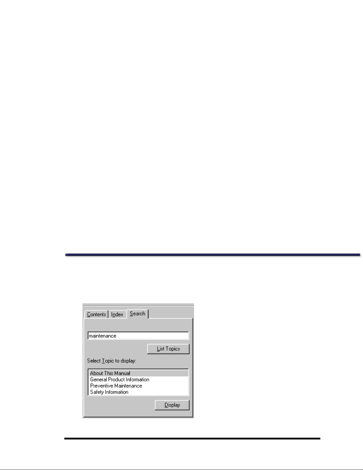
You can search for topics and content within theonline help.
1. Clickthe Search tab in theonline help window.
2. Type the contentfor which you are searching.
- 3 of 57-

3. ClickList Topics.
4. Clickany displayed topic name to display thedesired topic.
License and Warranty Information
Please carefully read thefollowing terms and conditions before installing or operating the GE Medical Systems Lunar Software
("Software").By installing or using the Software in your GE Medical Systems Lunar product, You indicateyour acceptance of these
terms and conditions. If You do not agree with theterms and conditions, do not install or operate the Software and return it to GE
MedicalSystems Lunar.
The Software has been provided to You for use on a specific GE Medical Systems Lunar product. The Software is provided under
the terms of this Agreement and is licensed to You, not sold. Your rights to use theSoftware are subject to the terms and conditions
contained within this License Agreementand GE Medical Systems Lunar reserves any rights not expressly granted to You. This
License is non-exclusiveand a non-transferable license to use the GE Medical Systems Lunar Software. Re-distribution of Software
or any documentation provided to you by GE Medical Systems Lunar is strictly prohibited.
This product includes some software components that are licensed under the GNU General Public License (GPL). Source code for
GPL components is available upon request.
The terms and conditions of this License Agreement and Limited Software Warranty are as follows:
1. LICENSE. This License allows You to:
(a) use theSoftware on a product in accordance with the accompanying documentation. To "use"the Software means that the
Software is either loaded in the temporary memory of a computer or installed on any permanent memory or media of a computer
(e.g.,hard disk, CD-ROM, optical disk, zip disk, and thelike);
(b) make one (1) copy, in machine-readable form, of the Software as provided to You solely for the purposes of backup; provided
that such copy includes thereproduction of any copyright noticeor other proprietary noticeappearing in or on such Software.
2. LICENSE RESTRICTIONS.
(a) YOU MAY NOT, EXCEPT AS EXPRESSLYPROVIDED FOR IN THIS LICENSE: (i) DECOMPILE, DISASSEMBLE,OR REVERSE ENGINEER THE
SOFTWARE(exceptto theextent applicable laws specifically prohibit such restriction); (ii) COPY, MODIFY, ADAPT, TRANSFER, TRANSLATE, RENT, LEASE,GRANT A SECURITY INTEREST IN, OR LOAN THE SOFTWARE OR ANY PORTION THEREOF; (iii) CREATE DERIVATIVE
WORKSBASED UPON THESOFTWARE OR ANY PORTION THEREOF; OR (iv) REMOVE ANY COPYRIGHT OR PROPRIETARY NOTICES OR
LABELSIN OR ON THE SOFTWARE.
(b) You understand that GE Medical Systems Lunar may updateor revisethe Software, and in so doing incur no obligation to furnish such updates to You under this License.GE Medical Systems Lunar has no obligation to improve, update or support the Software in thefuture.
(c) In theevent the instrument or product designated for theSoftware is sold or otherwise transferred to a third party, thatparty is
not authorized to use theSoftware unless theyfirst pay to GEMedical Systems Lunar the applicablelicense fee and agree to the
terms and conditions of a Software LicenseAgreement. Upon transfer of the Software or any copy thereof,the License granted
hereunder shall terminate immediately.
3. TERM AND TERMINATION.
This Licenseis effective until terminated. This License willterminateimmediately without noticefrom GE MedicalSystems Lunar or
judicial resolution if You fail to comply with any provision of the License. Upon any termination of this License, You agree to return
or destroy the Software, all accompanying written materials and all copies thereof in any form. Section 5 will survive any termination.
4. EXPORT LAW.
You agree that neither the Software nor any direct product thereof is being or will be shipped, transferred or re-exported, directly
or indirectly into any country prohibited under United States law or regulations promulgated thereunder.
5. WARRANTY.
GE Medical Systems Lunar warrants that,to thebest of our knowledge, thesoftware provided with this License will perform as
described in the product's operator's manual and the technical specification for this Software. This limited warranty is contingent
upon proper use of theSoftware and does not cover any Software which has been modified, subjected to malicious logic, unusual
physical or electrical stress, or used on computer equipment not specified by GE Medical Systems Lunar.
GE Medical Systems Lunar does not warrant that the functions contained in this Software will meet your requirements, or that the
operation of theSoftware willbe uninterrupted or error- free. Statements made about this Software do not constitute warranties
- 4 of 57-

and shall not berelied upon by You in deciding whether to purchase theGE Medical Systems Lunar product or use theSoftware. IN
NO EVENT SHALL GE MEDICAL SYSTEMSLUNAR BELIABLE TO YOU FOR ANY DAMAGESARISING OUT OF THE USEOR INABILITY TO USE
SUCH SOFTWARE.
THE SOLE AND EXCLUSIVE REMEDY IN THEEVENT OF DEFECT IS EXPRESSLY LIMITED TO THE REPLACEMENT OF THE SOFTWAREPROVIDED. IF FAILURE OF THE SOFTWAREHAS RESULTED FROMACCIDENT OR ABUSE, GE MEDICAL SYSTEMSLUNAR SHALLHAVE NO
RESPONSIBILITY TO REPLACE THESOFTWARE.
GE Medical Systems Lunar will consider this warranty to be void if You failto comply with theterms in theSoftware License Agreement.
6. TITLE.
Title, ownership rights, and intellectual property rights in theSoftware shall remain with GE MedicalSystems Lunar. This Software is
protectedby the copyright laws and treaties.
7. MISCELLANEOUS.
This Agreementrepresents the complete agreementconcerning this Licenseand may be amended only by a writing executed by
both parties. TheLicense is governed by the laws of theStateof Wisconsin, U.S.A. without regard to its conflictof laws principles. If
any provision of this Agreement is held by a court of competentjurisdiction to be unenforceable, that provision shall be enforced to
the maximum extentpermissible and/or reformed only to the extentnecessary to make it enforceable,and the remaining provisions of this Agreement willnot be affected or impaired in any way. If any legal action or proceeding is brought for the enforcement of this Agreement, or because of any alleged dispute, breach, default or misrepresentation in connection with any of the
provisions of this Agreement, the successful or prevailing party shall beentitled to recover reasonable attorneys' fees and other
costs incurred in such action or proceeding, in addition to any other relief to which such party may be entitled.
General Product Information
The bone densitometer is designed to estimate the bone mineral densityand body composition (lean and fat tissue mass) of
patients when medically indicated by their physicians. The manuals provide instructions for operating the software and scan
table,system information, and maintenance information.
Variables Affecting Scan Results
Scan results can be affected by operator technique and patientvariability:
1. Operator technique refers to patientpositioning and scan analysis. To minimize technique variables, 1) establish consistent positioning and scan analysis routines by using anatomical landmarks when positioning patients, and 2) during
analysis, manipulateraw scan data only when absolutely necessary.
2. Patient variabilityrefers to changes in the patient's medical history, metabolism, and diet.It also refers to diagnostic procedures that involve radionuclide uptake and medical treatment, and the presence of external radiation (particularly the
use of other radiation-generating devices in thevicinity of the system). To minimize patient variability, 1) thoroughly familiarize yourselfwith thepatient's history, and 2) installthe scanner in an environment effectively shielded from other
sources of external radiation.
CAUTION: United States Federal Law restricts this device to the sale, distribution, and use by or on the order of a physician (USA only).
Training Information
GE Medical Systems Lunar or authorized GE Medical Systems Lunar distributors provide individual, hands-on training as part of
the installation procedure for your system.(GE Medical Systems Lunar distributors provide training for systems installed outside
the United States.)An Applications Specialist provides information on software and hardware operations, and reviews thewarnings and cautions in the manuals.
IMPORTANT: Only trained technologists should operate the system. New technologists should receive
training prior to unsupervised operation of the system. Additional training sessions are available on
request for a nominal fee. For more information, contact the GE Medical Systems Lunar Customer Service Department at 800-334-5831, or your local GE representative.
- 5 of 57-

Cautions for DEXA Determinations
You should be aware of thefollowing factors which may affectthe clinical accuracy of DEXA spine estimates: marked distortions of
skeletal architecture-e.g.,osteophytes, degenerativedisc disease, spinal arthritis, spondylolisthesis, kyphoscoliosis, and vertebral
fractures-and significant calcium deposits in theaorta can falsely elevatespine bone mineral values. Regions that contain these
dystrophic calcifications can be excluded from thescan analysis in some cases. Thescanner can be used to monitor changes in
bone mineral over time in patients with these disorders, but caution must betaken in interpretation. Use DEXA estimates as an aid
to other methods in the evaluation of patientbone mineral status in theclinical setting.
In addition, spine estimates willbe difficultto interpretfor patients with orthopedic metal devices and previous surgical interventions, such as bone grafts. Radiographic contrast material and radiopharmaceuticals used for myelograms, barium enemas,
and other diagnostic tests preventaccurateestimates. Barium clears the body within a few days, but theoil-based dyes used in
myelograms several years ago may remain within the body for years. A three-day waiting period is sufficient time for barium and
most radiopharmaceuticals to becompletelydischarged from the body.
Femur estimates will be difficultto interpret for patients with orthopedic metal devices and previous surgical interventions. The
most common complicating factors for femur estimates are prostheticdevices and surgical implants in the region of the bone
scan. Results may be adversely affected if the patient has difficultywith thedesired 25° inward rotation of theleg or with maintaining this position without movement.
Total Body estimates require consistent patientpositioning for accurate results and will be difficultto interpret for patients with
orthopedic metal devices and previous surgical interventions. The operator should pay particular attention to the location of the
patient's arms, keeping thepositioning thesame for each scan. Results may be affected if the patient moves during the scan.
Precautions for Standard Operating Procedures
1. Do not attempt to operatethe scanner without first reading this manual.
2. Do not remove the assembly panels or attemptany repairs without prior instructions from authorized GE Medical Systems Lunar personnel.
3. Perform the QualityAssurance procedure each morning. If any test fails, check theposition of thecalibration block and
rerun the QA procedure. If a test fails again, contact GE MedicalSystems Lunar Support. Also, callGE Medical Systems
Lunar if more than two failures occur in a one-week period. If the room temperature changes more the5°C during the
day, then perform another Daily QA.
4. If thepatient is or might be pregnant, always contact the patient's physician before performing a scan.
5. Remain in the room with thepatient whilea scan is in progress. Assure the patient does not move during the measurement. Minimize the amount of time the patient lies flat on the scan table.
6. Restrictaccess to theroom to authorized personnel.
7. Do not attempt to service any of thesystem's electrical components while the scan table is turned ON. High voltage is
used to produce x-rays.
8. Radiation safety information is located within this manual you received with your system. Review this information before
operation.
9. To stop the scanner in an emergency, press the emergency stop button on thescan arm. DO NOT use theemergency
stop button to routinely abort a scan.
10. Remove any fluids which are spilled on pad or any surface of tableimmediately.
11. All surfaces should be cleaned to meet site's guidelines for handling blood and body fluids. Pad material may be damaged by certain chemicals Use appropriate hospital grade disinfectantfollowed by mild detergent.
12. Do not generatex-rays through the use of remoteapplications.
- 6 of 57-

13. Protectthe computer against malicious logic and unauthorized network access. Only allow authorized user access. Prevent virus attacks through the use of firewalls, anti-virus software and software patch updates. Contact your local GE representativefor more information.
14. DPX Duo: Extend thestep the full distance to provide maximum surface area for the patient to get on and off thetable
without risk of injury.
15. DPX Duo: Do not placean excessiveload on foot rest (stirrup), drawers, or leg extension.
16. DPX Duo: Do not sit on leg extension table.
Patents
This product is covered by theclaims of one or more of thefollowing patents:
U.S. patents #5,040,546, #5,306,306, #5,480,439, #5,533,084, #6,038,281, #6,081,582, #U520050249331A1,
#U520050247882A1, #U520050247880A1
Standard Operating Procedures
1. Quality Assurance: Every morning, before you start patientmeasurements, completethe daily Quality Assurance procedure. Refer to chapter 2 of the enCOREOperator's Manual. Make sure you save your printed results for future reference.
2. Measure Patients: If time allows, enter thePrimary, Secondary, and Additional data for thepatients you expect to measure during the day. Refer to chapter 3 of the enCOREOperator's Manual to measure a patient.
3. Analyze Results: Analyze and print results immediately after each patientmeasurementif time allows. Otherwise,
analyze all of thepatient files after the last patienthas been measured. Refer to chapter 4 of the enCOREOperator's Manual to analyze results.
4. Archive image files: Archive your image files beforeyou leave for the day. In the unlikely event of a computer malfunction, itis very important that you have archived files of all of your patientmeasurements to rebuild your database.
Refer to Archiveimage files on page 30 for archive procedures.
5. Shut down computer: At the end of theday, selectExitfrom the Main screen, selectShut Down from the Close window,
and click OK to close the program.
Note: Do not turn off the scanner at theend of theday for stationary systems.
Scanner Table Assembly
Note: Do not attempt to service the scanner table assembly. Please call GE MEDICAL SYSTEMSLunar Support or your GE MEDICAL
SYSTEMSLunar distributor.
Scanner table
The scanner table is used to support thepatientduring a measurement or general examination (DPX Duo). In addition, thex-ray
source assembly and other electronics are contained inside the scanner table.
Scanner arm
The laser light,emitted from an aperture on the scanner arm, helps you locate the measurement start position. Positioning
switches let you move the scanner arm until thelaser light is located at the correct start position. Thestart position is different for
each measurement type.
The DPX Duo and DPX Bravo scanner arm has a releaseand locking mechanism allowing the upper arm to swivel when the
scanner is idle. The scanner arm must be in the locked position over thescanner tableto perform a measurement.
- 7 of 57-

Display panel
The following describes theindicators located on thescanner arm display panel:
Indicator Status (on)
Green (power) Power is supplied to the scanner table.
Yellow (x-ray) X-ray tubeassembly is supplying x-rays.
Yellow (shutter) Shutter is open.
Amber (laser) Laser is on.
Emergency stop button
Push thered emergency stop button to stop thescanner arm and immediately shut down x-rays in an emergency. Do not use the
emergency stop button to routinelystop the scanner during normal operation.
Positioning switches
The positioning switches move the scanner arm and detector to themeasurement start position (thelaser light indicates the position of the detector). The Back/Front switch moves thedetector across the width of the scanner table. The Left/Right switch moves
the scanner arm down thelength of the scanner table.
Swing arm position sensing switches (DPX Duo, DPX Bravo)
The swing arm position sensing switches detectthe locking status of the swing arm and the swing arm latch. The swing arm latch
must be locked and the swing arm must be in the locked position over thescan table before a measurementcan be performed.
Release of the swing arm latch during a measurementwill abort thescan and themeasurementdata will be lost.
iDXA Start Scan button
The start scan button initiates the patient measurement. The start scan button is located on the display panel near thepositioning
switches.
System Safety
Obey these safetyguidelines at all times:
● Read the manual before you operate the scanner.
● Thetechnologist operating thescanner must remain in the room with thepatientduring the measurement.
● Do not attempt to service the scanner. Please callGE MEDICAL SYSTEMS Lunar Support or your GE MEDICAL SYSTEMS
Lunar Distributor.
● When thescanner is not in use, make sure the Shutter Open, X-ray, and Laser lights are off.
● Do not put excessive pressure on thescanner arm.
● Use the scanner table for patient measurements and examinations (DPX Duo) only: do not sit, stand or lieon the tablefor
other purposes.
● Do not let liquids touch the computer or scanner tablemechanics and electronics.
Operator Safety
Personnel monitors
Personnel monitors are not necessary to operate the scanner.
It is not likely that you can receive more than 25% of themaximum permissiblex-ray dose from the scanner. However, some facilities choose to use personnel monitors. Refer to your city, county or state Health Departmentor Radiation Safety Officer for your
facility's policy.
Film badges and thermal luminescent dosimeter (TLD) badges are obtained from a supplier accredited by the National Voluntary
Laboratory Accreditation Program for personnel dosimetry processing.
The following is a sample situation for a clinicmeasuring an AP spine and Dual Femur on 5 subjects per day with an exposure rate
of 0.18mR/hr at a distance of 2 meters estimated from theiDXA isodose curves.
- 8 of 57-
Sample Calculation for Estimated Exposure per Year from Scatter with iDXA Densitometer
Scan Type Mode Average Scans/Day Scan Time/Day
(sec/day)
AP Spine Standard 5 260 260
Dual Femur Standard 5 535 535
2.5 mA Scan Time per Day (sec) 795
2.5 mA Scan Time per Day (hours) 0.221
2.5 mA Scan Time per Week (hours) 1.11
2.5 mA Scan Time per Year (hours) 57.5
2.5 mA Exposure from Isodose Plots (mR/hr) 0.18
Total Exposure for 1 Year (mR) 10.3
Total Absorbed Dose for 1 Year (mRad) 0.92 Rad/R 9.5
Equivalent2.5 mA
Scan Time/day
(sec/day)
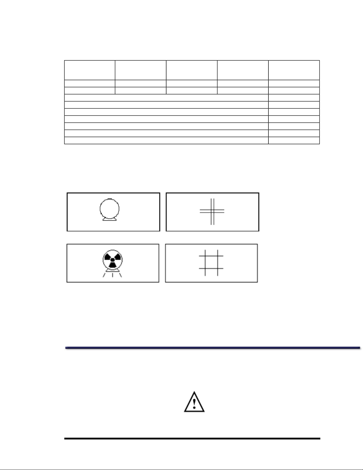
X-ray and shutter graphics
During a measurement or QualityAssurance procedure, x-ray and shutter graphics are shown on the computer monitor. The
graphics are green to indicate x-rays are off and theshutter is closed, and yellow to indicate x-rays are on and the shutter is open.
X-rays off and shutter closed (green):
X-rays on and shutter open (yellow):
X-ray shutter
When power to thescanner is interrupted during a measurement or QualityAssurance procedure, theshutter closes and the xray tube stops generating x-radiation.
X-ray power supply
The x-ray tube assembly uses high voltage to generate x-rays. DO NOT touch internal components. DO NOT attempt to service
internal components.
Patient Safety
Pinch points
The Warning label identifies thelocation of possiblepinch points.
When thescanner arm is in motion, make sure possible pinch point areas are clear at all times. Patientlimbs must remain inside
the boundaries of the tabletop. A pinch point is possible between the scanner arm and table.
- 9 of 57-
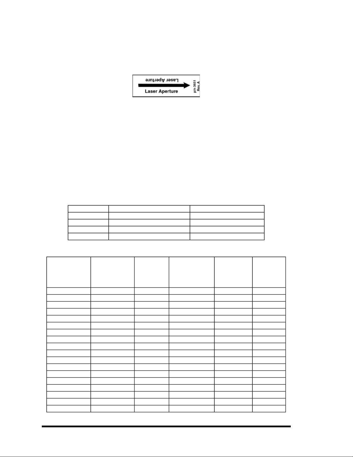
Laser Safety
DO NOT STARE INTO THE LASER BEAM during patient positioning and Quality Assurance procedures. The labelthat follows is
located on the scanner arm and shows the location of the laser aperture.
Radiation Safety
X-ray exposure: The system makes radiation when electric voltageis suppliedto, and current flows through, thex-ray tube. Dur-
ing a measurement, the shutter opens to let a beam of radiation pass through the scanner table and patient. The nominal radiation field at the iDXA scanner table top is 18.4 mm x 3.3 mm, at theProdigy table top is 19.5 mm x 3.4 mm and at the DPX series
table top it is 2 mm. Lead oxide shielding surrounds the x-ray tube insert insidethe tube housing assembly and reduces radiation
levels around the scanner table.
Skin entrance dose: A Victoreen model 530 Precision Electrometer/ Dosemeter with a Model 660-5 Ion Chamber was used to
measure the X-ray entrance dose. Refer to the"Current and Typical Dose Tables" for irradiation times and skin entrance doses.
Measurement modes
Patient thickness determines the appropriate measurement mode. Theprogram selects theappropriatemode based on the
patient's height and weight.
Lunar enCORE Systems
iDXA, PRODIGY, PRODIGY Advance DPX Series
Mode Patient thickness Patient thickness
Thick >25 cm >25 cm
Standard 13-25 cm 15-25 cm
Thin <13 cm <15 cm
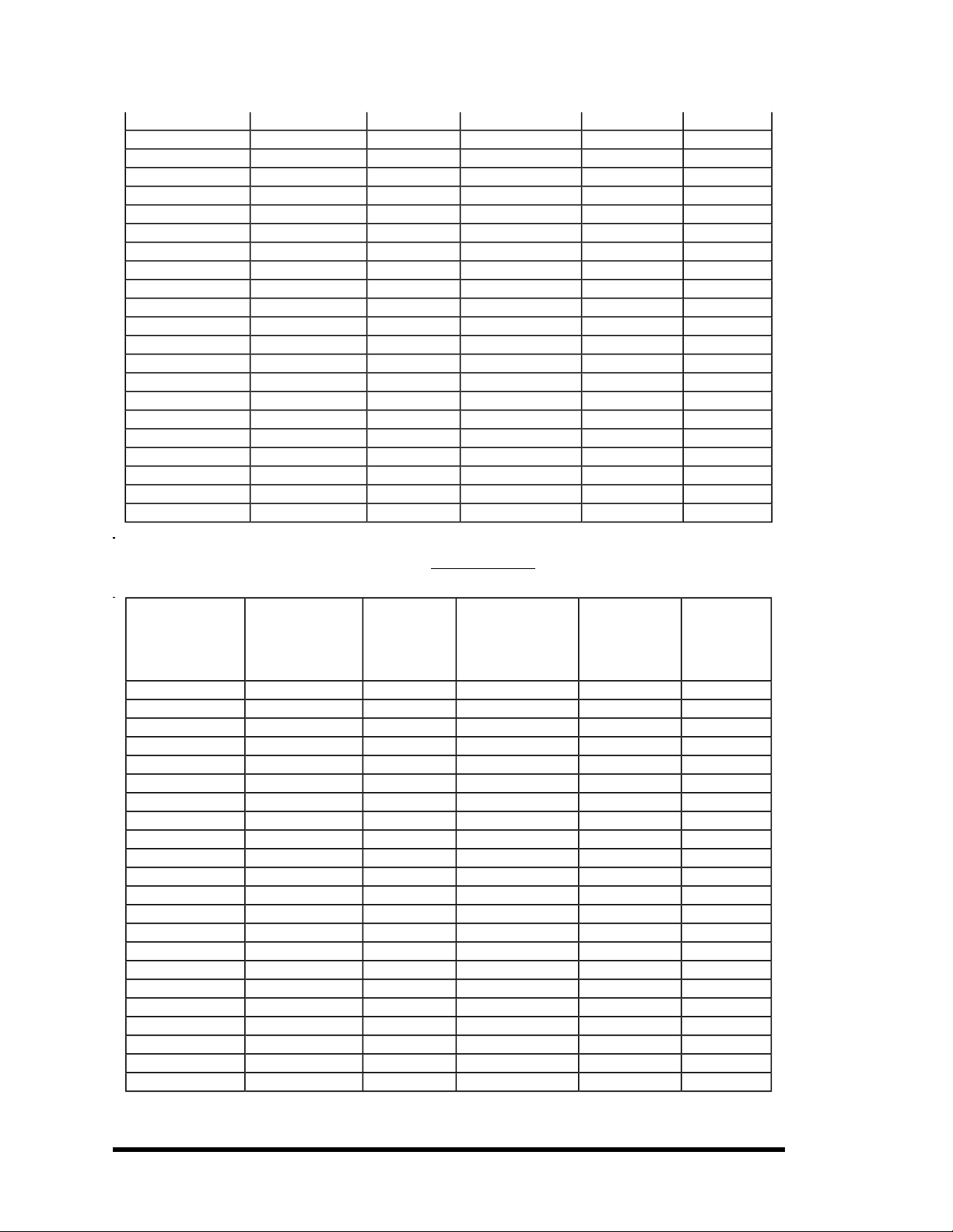
Current and typical dose information for Lunar iDXA modes
Typical Measurement Area
Site Mode
AP Spine Thick 2.500 19.0 x 18.0 109 329
AP Spine Standard 2.500 19.0 x 18.0 52 146
AP Spine Thin 0.625 19.0 x 18.0 52 37
AP Spine QuickView 2.500 19.0 x 18.0 23 47
Femur Thick 2.500 20.5 x 17.0 112 329
Femur Standard 2.500 20.5 x 17.0 54 146
Femur Thin 0.625 20.5 x 17.0 54 37
Femur QuickView 2.500 20.5 x 17.0 24 47
DualFemur Thick 2.500 2 x 20.5 x 17.0 224 329
DualFemur Standard 2.500 2 x 20.5 x 17.0 107 146
DualFemur Thin 0.625 2 x 20.5 x 17.0 107 37
DualFemur QuickView 2.500 2 x 20.5 x 17.0 48 47
H
APVA
APVA
APVA
H
H
Thick 2.500 42.7 x 18.0 117 146
Standard 2.500 42.7 x 18.0 117 146
Thin 0.625 42.7 x 18.0 117 37
A
Current
(mA)
B
L x W cm x cm
C,D
Irradiation
times
C,D,E
(sec)
Estimated
Skin
Entrance
Dose
F,G
(μGy)
- 10 of 57-

Forearm Standard 0.188 14.2 x 10.0 24 10
Hand Standard 0.188 25.3 x 18.0 69 10
Total Body Thick 0.188 196.8 x 66 796 6
Total Body Standard 0.188 196.8 x 66 436 3
Total Body Thin 0.188 196.8 x 66 436 3
H
LVA
H
LVA
Lateral Spine Standard 2.500 19.0 x 18.0 104 329
Orthopedic
Femur Thick 2.500 23.7 x 15.0 109 329
Orthopedic
Femur Standard 2.500 23.7 x 15.0 53 146
Orthopedic
Femur Thin 0.625 23.7 x 15.0 53 37
Small Animal Standard 0.188 75.8 x 25.0 264 10
A
All modes are 100kV, ±1kV.
B
Tube current is ±1% at themaximum current.
C
Imaging timemeasured from shutter open to shutter close,90% to 100% of indicated value.
D
Sizes of measurement areas and irradiation times willbe less than those listed above ifyou use the SmartScan feature.
E
Measurement lengths and times are dependenton patient height and product version.
F
Dose measurements are constrained by Daily QA limits.
G
Irradiation times and dose values do not consider a “sweep retry” feature which can double thedose for a single transverse
sweep within an entire scan. If a retry occurs a slight increase in irradiation time and skin entrance dose would be expected. The
retry feature reduces need to rescan entire patient.
H
The activation of thespine geometry application permits a maximum scan length up to 69.5 cm.
Standard 2.500 42.7 x 20.0 271 329
Thin 0.625 60.0 x 20.0 381 82
Current and typical dose information for Lunar PRODIGY, PRODIGY Advance, PRODIGY Pro modes
Estimated
Typical Measurement Area
Site Mode
AP Spine Thick 3.000 15.1 x 12.1 56 83
AP Spine Standard 3.000 15.1 x 12.1 28 37
AP Spine Thin 0.750 15.1 x 12.1 28 9
AP Spine QuickView 3.000 15.1 x 12.1 14 12
Femur Precise 3.000 15.1 x 12.1 56 83
Femur Thick 3.000 15.1 x 12.1 56 83
Femur Standard 3.000 15.1 x 12.1 28 37
Femur Thin 0.750 15.1 x 12.1 28 9
Femur QuickView 3.000 15.1 x 12.1 14 12
DualFemur Thick/Precise 3.000 2 x 15.1 x 12.1 112 83
DualFemur Standard 3.000 2 x 15.1 x 12.1 55 37
DualFemur Thin 0.750 2 x 15.1 x 12.1 55 9
DualFemur QuickView 3.000 2 x 15.1 x 12.1 28 12
1
Current
(mA)
2
L x W cm x cm
4,5
Irradiation
times
3,4,5
(sec)
Skin
Entrance
Dose
(μGy)
6,7
- 11 of 57-
Forearm Standard 0.150 13.4 x 10.0 21 2
Hand Standard 0.150 23.5 x 18.0 61 2
Total Body Thick 0.150 151.5 x 60 532 0.8
Total Body Standard 0.150 151.5 x 60 295 0.4
Total Body Thin 0.150 151.5 x 60 295 0.4
Lateral BMD Standard 3.000 15.1 x 12 56 83
LVA Standard 3.000 38.7 x 15.0 175 83
APVA Thick 3.000 38.7 x 15 85 37
APVA Standard 3.000 38.7 x 15 85 37
APVA Thin 0.750 38.7 x 15 85 9
Orthopedic Femur Thick 3.000 20.2 x 15 91 83
Orthopedic Femur Standard 3.000 20.2 x 15 44 37
Orthopedic Femur Thin 0.750 20.2 x 15 44 9
Small Animal Standard 0.15 75.7 x 25.0 261 1.8
Current and typical dose information for Lunar PRODIGY Primo modes
Estimated
Typical Measurement Area
Site Mode
AP Spine Thick 1.500 15.1 x 12.1 96 74
AP Spine Standard 1.500 15.1 x 12.1 56 42
AP Spine Thin 0.375 15.1 x 12.1 56 10
Femur Thick 1.500 15.1 x 12.1 96 74
Femur Standard 1.500 15.1 x 12.1 56 42
Femur Thin 0.375 15.1 x 12.1 56 10
DualFemur Thick 1.500 2 x 15.1 x 12.1 193 74
DualFemur Standard 1.500 2 x 15.1 x 12.1 112 42
DualFemur Thin 0.375 2 x 15.1 x 12.1 112 10
Forearm Standard 0.150 13.4 x 10.0 21 2
Total Body Thick 0.150 151.5 x 60 532 0.8
Total Body Standard 0.150 151.5 x 60 295 0.4
Total Body Thin 0.150 151.5 x 60 295 0.4
Lateral BMD Standard 3.000 15.1 x 12 56 83
LVA Standard 3.000 38.7 x 15.0 175 83
1
Current
(mA)
2
L x W cm x cm
4,5
Irradiation
times
3,4,5
(sec)
Skin
Entrance
Dose
(μGy)
6,7
APVA Thick 3.000 38.7 x 15 85 37
- 12 of 57-

APVA Standard 3.000 38.7 x 15 85 37
APVA Thin 0.750 38.7 x 15 85 9
Orthopedic
Femur Thick 3.000 20.2 x 15 91 83
Orthopedic
Femur Standard 3.000 20.2 x 15 44 37
Orthopedic
Femur Thin 0.750 20.2 x 15 44 9
Current and typical dose information for Lunar DPX-PRO/NT/Duo/Bravo modes
Typical Measurement Area
Site Mode
AP Spine Thick 1.500 15.1 x 12.1 215 41
AP Spine Standard 1.500 15.1 x 12.1 108 20
AP Spine Thin 0.375 15.1 x 12.1 215 5
AP Spine QuickView
1
Current
2
(mA)
Not Avail-
able
L x W cm x cm
4,5
Irradiation
times
3,4,5
(sec)
Estimated
Skin
Entrance
Dose
6,7
(μGy)
Femur Precise 1.500 14.0 x 12.0 221 41
Femur Thick 1.500 14.0 x 12.0 221 41
Femur Standard 1.500 14.0 x 12.0 132 20
Femur Thin 0.375 14.0 x 12.0 221 5
Not Avail-
Femur QuickView
DualFemur Thick/Precise 1.500 2 x 14.0 x 12.0 443 41
DualFemur Standard 1.500 2 x 14.0 x 12.0 264 20
DualFemur Thin 0.375 2 x 14.0 x 12.0 443 5
DualFemur QuickView
Forearm Standard 0.050 11.5 x 10.0 286 3
Hand Standard
Total Body Thick 0.100 151.5 x 60 1337 0.3
Total Body Standard 0.100 151.5 x 60 670 0.2
Total Body Thin 0.100 151.5 x 60 900 0.2
Lateral BMD Standard 1.500 12.0 x 12.0 189 41
LVA Standard
able
Not Avail-
able
Not Avail-
able
Not Avail-
able
APVA Thick
APVA Standard
Not Avail-
able
Not Avail-
able
- 13 of 57-
Not Avail-
APVA Thin
Orthopedic Femur Thick 1.500 20.1 x 15.0 385 41
Orthopedic Femur Standard 1.500 20.1 x 15.0 223 20
Orthopedic Femur Thin 0.375 20.1 x 15.0 385 5
Small Animal Standard
able
Not Avail-
able
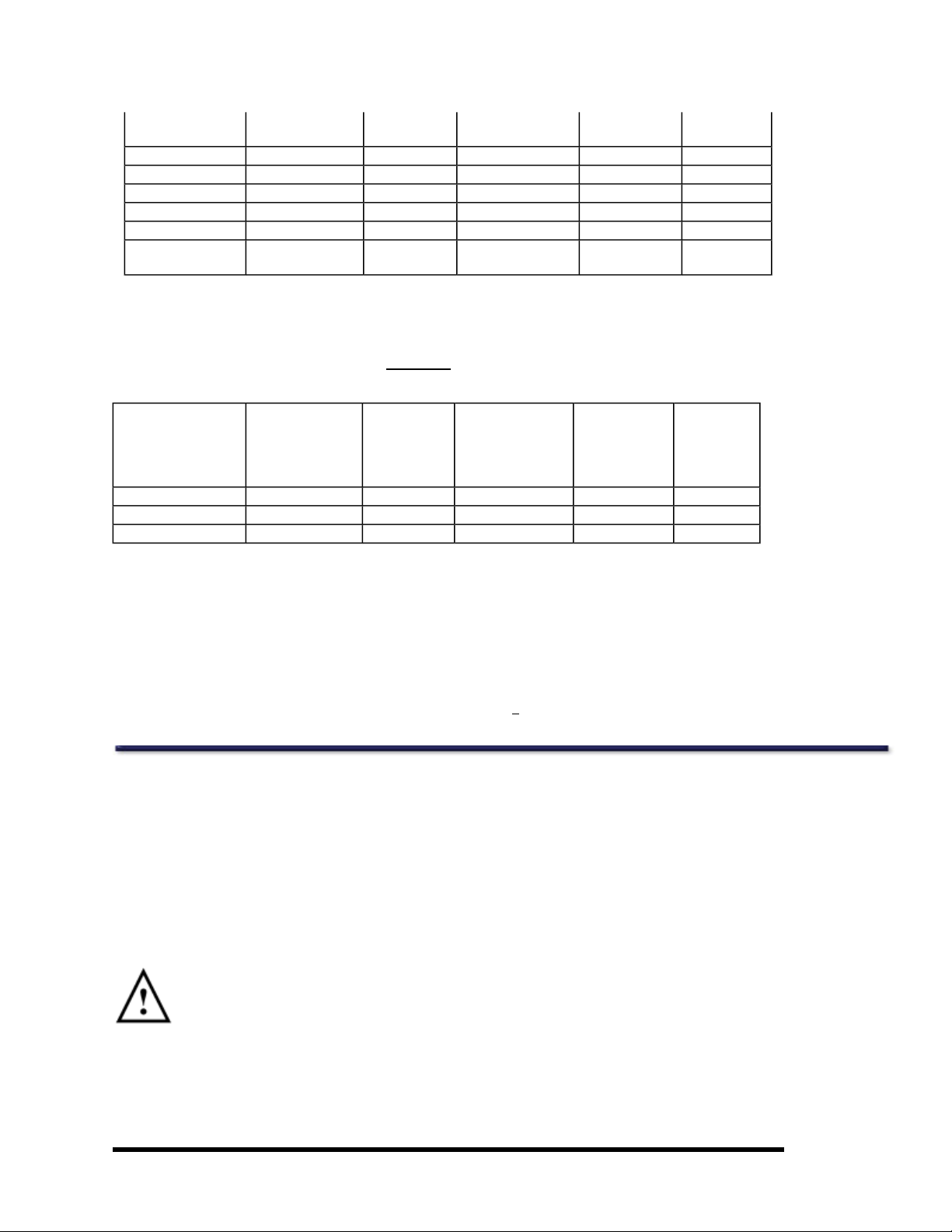
Current and typical dose information for DPX-MD+ modes. Note, Standard mode is replaced with
Standard-MD mode.
Estimated
Typical Measurement Area
Site Mode
AP Spine Standard-MD 0.750 15.0 x 12.0 212 20
Femur Standard-MD 0.750 15.0 x 12.0 236 20
Orthopedic Femur Standard-MD 0.750 15.0 x 12.0 336 20
1
All modes are 76kV, ±1kV.
2
Tube current is ±1% at themaximum current.
3
Imaging timemeasured from shutter open to shutter close,90% to 100% of indicated value.
4
Sizes of measurement areas and irradiation times willbe less than those listed above ifyou use the SmartScan feature.
5
Measurement lengths and times are dependenton patient height and product version.
6
Dose measurements are constrained by Daily QA limits. For example,the maximum spine (standard mode) range is 30 to 85μGy
for Prodigy densitometers and 8 to 28μGy for DPX series densitometers.
7
Irradiation times and dose values do not consider a “sweep retry” feature which can double thedose for a single transverse
sweep within an entire scan. If a retry occurs a slight increase in irradiation time and skin entrance dose would be expected. On
Lunar Prodigy scanners DF+12000 and above, all Prodigy Advance,and DPX+NT scanners running version 8 software and
newer, a sweep may be retried one time during acquisition. A maximum of two sweeps can be retried per scan. Theretry feature
reduces need to rescan entirepatient.
1
Current
(mA)
2
L x W cm x cm
4,5
Irradiation
times
3,4,5
(sec)
Skin
Entrance
6
Dose
(μGy)
Mechanical Safety
The scanner arm moves down the entire length of thescanner table. Make sure thepatient does not interfere with the movement
of thescanner arm to preventpossible injury. In addition, make sure that there are no objects behind the scanner tablethat might
obstruct movementof the scanner arm.
Weight applied to the Lunar iDXA must not exceed 204kg (450 pounds). Weight applied to the Lunar DPX-Pro/NT/MD+ scan table
bed must not exceed 136kg (300 pounds). Weight applied to the Lunar PRODIGY, PRODIGY Advance, PRODIGY Primo, DPXDuo/Bravo scan table bed or footstep (DPX Duo) must not exceed 159kg (350 pounds).
External Symbols
Attention: shows the Operator's Manual contains important safety information such as the location of pinch
points.
- 14 of 57-
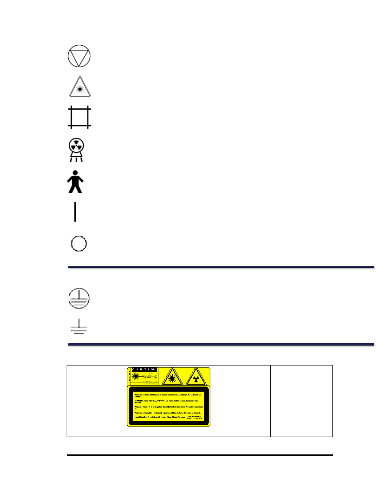
Emergency Stop Button: shows the location of theemergency stop button.
Laser On: shows the location of theLaser On indicator.
Shutter Open: shows the location of theShutter Open indicator.
X-ray On: shows the location of the X-ray On indicator.
Type B Equipment: shows that the scanner has Type B protection against electrical shock.
Power On: shows the location of the Power On indicator and theswitch position for Power On.
Power Off:shows the switch position for Power Off.
Internal Symbols
Protective Earth: shows the location of a ProtectiveEarth terminal.
Functional Earth: shows the location of a Functional Earth terminal.
Labels
Laser Caution and Ionizing Radiation Label:
Shows that thescanner
uses a Class II laser. The
label includes the
required symbols and
precaution (Laser Radiation: Do not stare into
beam. Class II Laser
Product).
- 15 of 57-
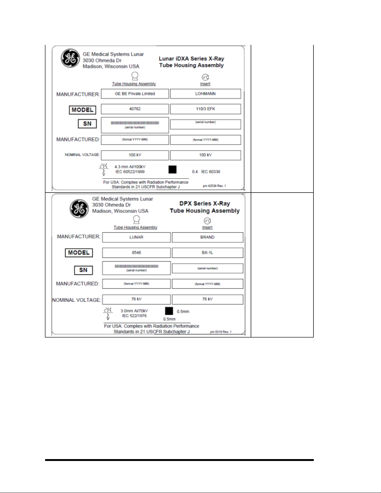
Tube Head Assembly
"Lunar iDXA" Label:
This label gives tube
head assembly and xray source characteristics information. It
is located on the tube
head assembly and the
foot panel of the
scanner. Thelabel
appearance may vary
from the one displayed
here. The Lunar iDXA
series labelcovers appropriate Tube Head
Assembly for Lunar iDXA
scanners.
Tube Head Assembly
“DPX Series” Label: This
label gives tube head
assembly and x-ray
source characteristics
information. It is located
on the tube head
assembly and the foot
panel of the scanner.
Tube Head Assembly
label covers DPX-NT,
DPX-MD+, DPX Bravo,
and DPX Duo.
- 16 of 57-
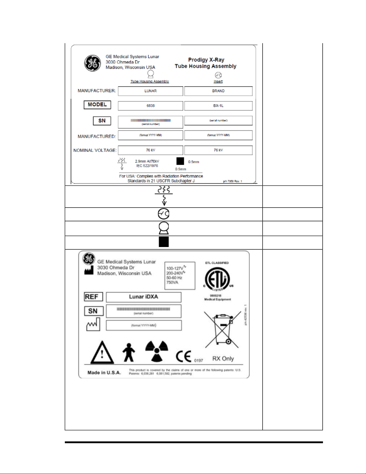
Tube Head Assembly
“Prodigy Series” Label:
This label gives tube
head assembly and xray source characteristics information. It
is located on the tube
head assembly and the
foot panel of the
scanner. Thelabel
appearance may vary
from the one displayed
here. The Prodigy series
label covers appropriate
Tube Head Assembly for
Prodigy and Prodigy
Advance scanners.
Inherent Filtration: Symbol from EN60417-1,
5381
Tube Insert: Symbol
from EN60417-1, 5337
X-ray Source: Symbol
from EN60417-1, 5338
Focal Point: Symbol
from EN60417-1, 5327
System Label: This label
gives system input
power requirements and
compliance information.
It is located on the foot
panel of scanners. The
Attention symbol indicates need to read
accompanying documents. Person symbol
refers to Type B applied
part for degree of electric
shock protection per
EN60601-1. The Fan
symbol denotes ionizing
radiation is generated.
The CE mark shows
compliance with theMedical Device Directive
93/42/EEC.The ETL mark
shows compliance to UL
60601-1 and CAN/CSA
C22.2 No. 601 The
WasteReceptaclemark
indicates that the waste
of electricaland electronic equipmentmust
not be disposed as
- 17 of 57-
unsorted municipal
waste and must be collected separately. Please
contact an authorized
representativeof the
manufacturer for information concerning the
decommissioning of
your equipment.
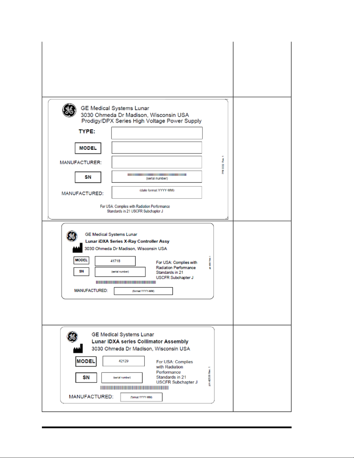
High Voltage Power
Supply: This label gives
high voltage power
supply (x-ray generator)
information. It is located
on the high voltage
power supply and foot
panel of the scanner.
Prodigy/DPX series High
Voltage Power Supply
label covers all the latest
Lunar products since
they use the same HVPS
part number.
X-ray Controller: This
label shows x-ray controller compliance. It is
located near the x-ray
controller and on the
foot panel of the
scanner. TheLunar iDXA
X-ray Controller
Assembly labelcovers all
the Lunar iDXA products.
Prodigy/DPX series Xray Controller Assembly
label covers all the latest
Lunar products. Labels
show model/serial
number for that specific
product.
Collimator Assembly:
This label gives collimator assembly information. It is located on
the collimator and foot
panel of the scanner.
The Lunar iDXA Collimator Assembly label
covers all Lunar iDXA
products. Prodigy/DPX
series Collimator
Assembly labelcovers
latestLunar products.
Labels show model/se-
- 18 of 57-
 Loading...