

Page 1
Telephone ringer amplifier with
flasher and door bell
User Guide
Indicateur d’appel téléphonique avec
flash et sonnette
Notice d’utilisation
CL2
Telephone call indicator
Page 2
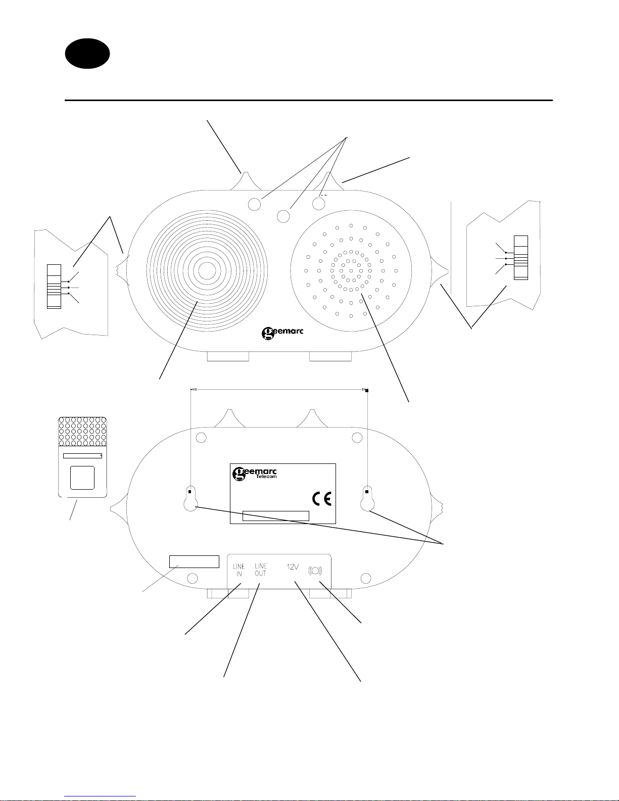
DESCRIPTION
GB/F
FRONT
AVANT
4 ringer settings
4 configurations de sonnerie
V olume control
Réglage du volume
Phone tone control
Réglage de la tonalité
téléphone
(*) Modular jack PTT line
Prise ligne PTT
(*) PTT modular jack for external connection
Prise PTT pour connection externe
(*) Adaptor jack
Prise adaptateur
(*) Shaker jack
Prise coussinet vibrant
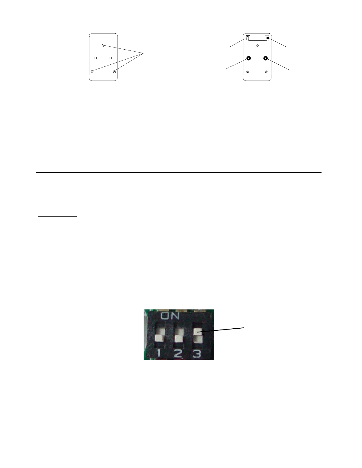
Wall mounting
screw holes
Ouvertures pour vis
de fixation murale
101 mm
Strobe flasher
Flash lumineux
Loud sound alarm
Sonnerie électronique
(*) Classified TNV-3 according to EN60950 standard.
Classée TNT-3 selon la norme EN60950
Doorbell tone control
Réglage de la tonalité
de sonnette
DOORBELL TONE
1 2 3
1 2 3
RING TONE
REAR
ARRIERE
Door bell LED
Voyant repères sonnette
Door Bell
Sonnette
For product support & help
www.geemarc.com
or Telephone 01707 384438
CL2
Access cover mini -
switch
Couvercle accès
mini-interrupteurs
DC
Page 3
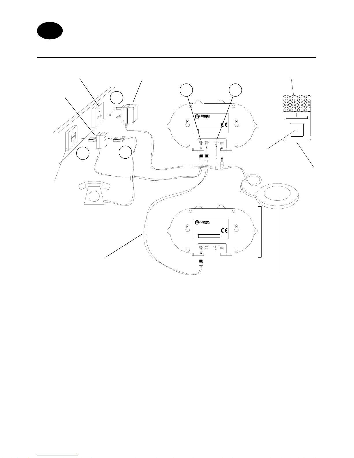
INSTALLATION (See drawing)
1 - Connect the PTT line cord.
2 - You have the option of connecting your telephone in the double plug.
3 - Connect the PTT double plug in the wall socket.
4 - If necessary connect the required shaker (SHAKCL_BLK only) to the
shaker plug.
5 - Connect the adaptor line cord.
6 - Connect the adaptor in the wall socket. (*)
(*) Classified “hazardous voltage” according to EN60950 standard.
Electrical connection : The apparatus is designed to operate from a 230V 50Hz supply
only. (Classified as «hazardous voltage» according to EN60950 standard).
The apparatus does not incorporate an integral power on/off switch. To disconnect the
power, either switch off supply at the mains power socket or unplug the AC adaptor. When
installing the apparatus, ensure that the mains power socket is readily accessible.
T elephone connection : Voltages present on the telecommunication network are classified
TNV-3 (Telecommunication Network Voltage) according to the EN60950 standard.
Option :
Special cable to link two CL2’s
(ref.: CL2RJ1 1/RJ1 1)
Option : Shaker
(ref.: SHAKCL_BLK only)
1
3
5
2
4
PTT double
plug
AC/DC adaptor
230V
For product support & help
www.geemarc.com
or Telephone 01707 384438
For product support & help
www.geemarc.com
or Telephone 01707 384438
CL2
CL2
2 nd CL2
GB
Screw wall mount access
Door Bell
Door Bell
Button
PTT wall
socket
Page 4
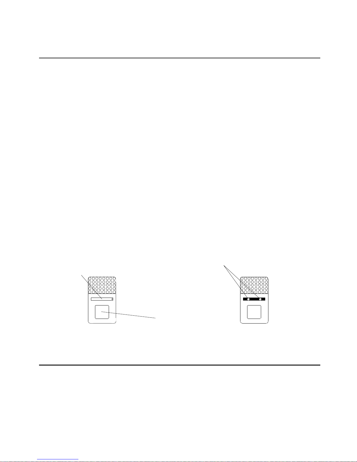
DOOR BELL
1 - DOOR BELL WALL MOUNT
The door bell is supplied with a 23A 12V battery , it is not necessary to open
the door bell to set the battery.
Note: The door bell works only when you press the button.
To wall mount the door bell simply follow instructions below:
- Use the wall mount template to mark the holes on the wall (screws and
pins are provided with the CL2).
- Open the screw wall mount access cover located in the middle of the door
bell with a small needle or a small screw driver , there is a little hole to introduce
the needle or the screw driver into the cover .
Place and align the two holes in the same axes as the holes on the wall,
insert the screw , then replace the cover. The Door bell is now ready to use.
Note: Do not place the base and the door bell onto metallic base or
near electric equipment (like TV , Radio, computer , washing machine...).
The CL2 will work within a range of 60 m in an environment where
there are no obstacles and 20 m in an environment which contains a
wall or metallic structure.
2 - CHANGE THE BATTERY
To replace the battery , remove the door bell from the wall, unscrew the three
screws located on the base and open the box to get access to the battery
compartment. Replace the battery.
Close and screw the box with the screw , and wall mount it again. Pay attention
to the two plastic parts A and B for which make this appliance waterproof.
Screw wall mount
access cover
with name
template
Door Bell
Button
Wall mount holes
Page 5
Note: Do not use a rechargable battery, do not put the battery into the
household rubbish. Pay attention to the battery regulation regarding
battery disposal.
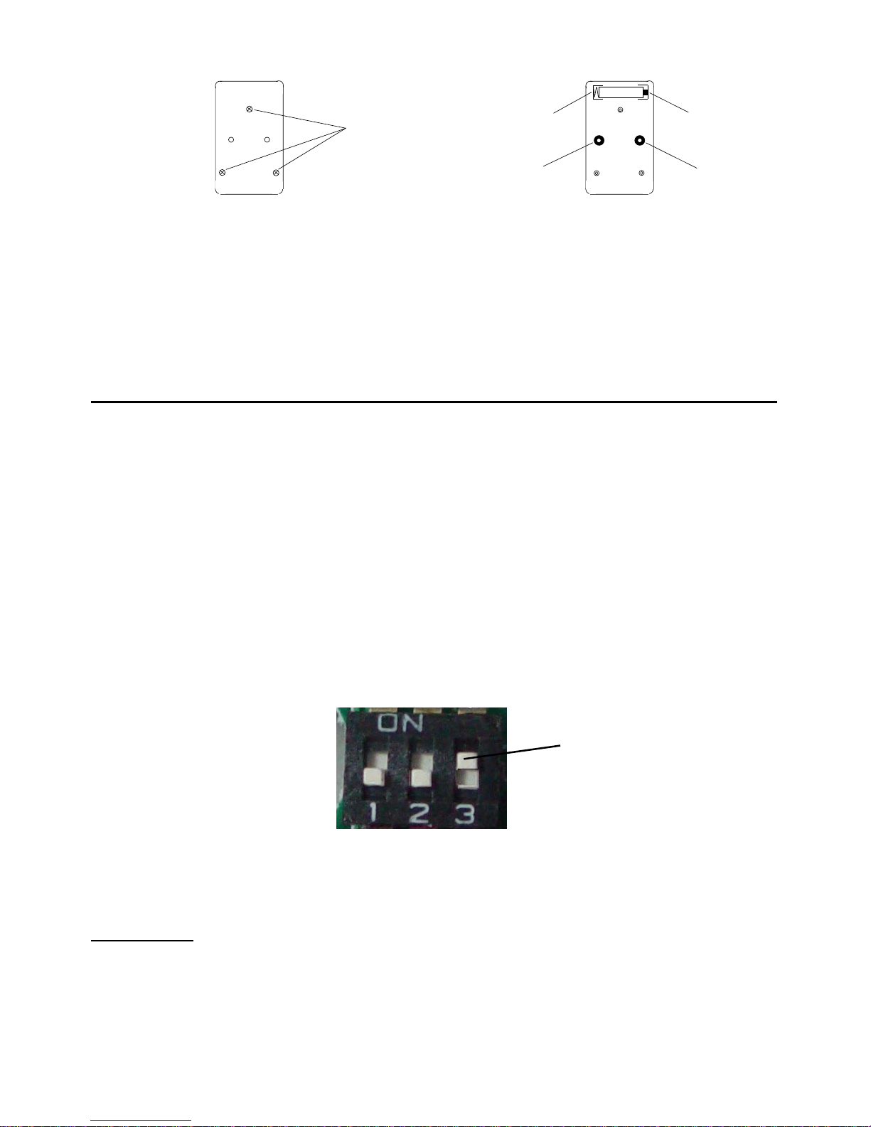
3 - SETTING
The door bell and the CL2 have been preset in factory by a mini switch
combination
Door bell :
3 mini switches > set to select ORANGE LED on the CL2
Door bell and CL2 : the same combination by 8 mini switches to make
sure of the works
If you want , you can change these combination
Open the door bell as described previously.
Modify LC2 Led color
1 ‘ON’ = RED 3 ‘ON’ = ORANGE
2 ‘ON’ = GREEN ( factory preset)
Example : To change to RED led , switch 3 then set 1 ‘ON’
Note : Only one switch has to be ON otherwise the others LED will light
too
The color of the door bell button can’t be changed ( lighted when
you press on )
Screw
to open
Base
Battery - Battery
+
AB
BA T
Page 6
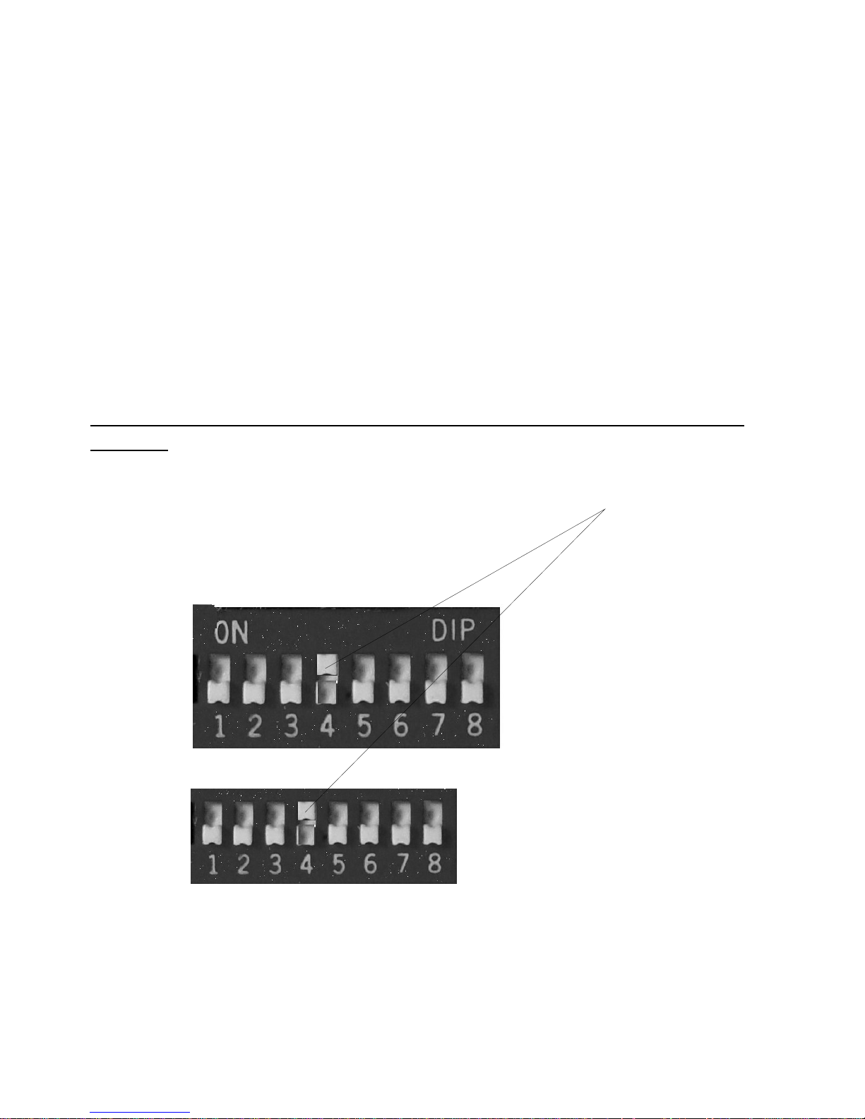
Combination change of the broadcasting validation
In case of interferences with a similar device or if you buy the remote
control, to change the combination proceed like below :
- Remove the cover ( on CL2 rear ) to access the mini switches ( see
description sheet )
- Open the door bell as described in paragraph 2
You may change the combination on modifying the switches position (
‘OFF’ or ‘ON’ )
Each switch must be in the same position as well in the CL2 than in the
door bell
Shown below an example of combination with only the fourth switch ‘ON’
all others are ‘OFF’
Door bell
OFF
CL2
ON
OFF
X X X 0 X X X X Remote control ( option)
switches combination meaning
Legend : 0 means ON , X means OFF
Buying option : - extra door bell ( 2 max )
- Remote control
- A shaker
Page 7

4 - ALARM OPERATION
4.1 - RINGER SETTING
Choose which alarm mode you want by moving the alarm mode switch to
one of the following positions:
0 : no alarm
: both strobe flasher and sound alarm activated
: both strobe flasher and shaker (if connected) activated
: both sound alarm and shaker (if connected) activated
4.2 - VOLUME CONTROL SLIDE SWITCH
Set the volume of the alarm sound.
4.3 - RING TONE CONTROL SWITCH (3 POSITIONS)
Set the tone of the ringer alarm sound (incoming call).
4.4 - DOOR BELL TONE CONTROL SWITCH (3 POSITIONS)
Set the tone of the door bell alarm sound.
4.5 - USE THE DOOR BELL
To use the door bell simply press the door bell button, CL2 will work with the
alarm settings, alarms will work only when pressing the door bell button
(two alarm for each time you press).
TROUBLE SHOOTING
The phone ring not - Ckeck the right connexion between the wall
the CL2 socket and CL2 “Line In” plug
- Check that the ring button is not set on “without”
The door bell doesn’t - AC/DC adapt ator must be pluged
send alarm - Open the door bell, check the battery position + -
- check that the 8 switches setting is the same as
in the CL2
Page 8

For product support and help visit our website at
www.geemarc.com
telephone 01707 384438
or fax 01707 372529
GUARANTEE
From the moment your Geemarc product is purchased, Geemarc guarantee it for the period of one year .
During this time, all repairs or replacements (at our discretion) are free of
charge. Should you experience a problem then contact our helpline or visit
our website at www.geemarc.com.
The guarantee does not cover accidents, negligence or breakages to any
parts.
The product must not be tampered with or taken apart by anyone who is not
an authorised Geemarc representative.
The Geemarc guarantee in no way limits your legal rights.
IMPORT ANT : YOUR RECEIPT IS P ART OF YOUR GUARANTEE AND MUST
BE RET AINED AND PRODUCED IN THE EVENT OF A WARRANTY CLAIM
Please note: The guarantee applies to the United Kingdom only.
Declaration : Geemarc Telecom SA hereby declares that this product is in
compliance with the essential requirements and other relevant provisions of
the Radio and Telecommunications Terminal Equipment Directive 1999/5/
EEC and in particular article 3 section 1a, 1b and section 3.
Page 9

INSTALLATION
1 - Branchez le cordon PTT ( Line In )
2 - Branchez votre prise téléphonique dans la prise double PTT.
3 - Branchez la prise double téléphonique dans votre prise téléphonique
murale.
4 - Connectez éventuellement le coussinet vibrant (ref: SHAKCL_BLK
uniquement) à la prise vibreur .
5 - Branchez le cordon de l’adaptateur secteur.
6 - Branchez l’adaptateur secteur au réseau électrique (*).
(*) Classé “tension dangereuse” selon la norme EN60950.
Raccordement électrique : l’appareil est prévu pour fonctionner uniquement avec
l’adaptateur secteur 230V 50Hz fourni. (Tension classée “dangereuse” selon les
critères de la norme EN60950). Par précaution en cas de danger, le bloc alimentation
secteur sert de dispositif de sectionnement de l’alimentation 230V. Il doit être installé à
proximité du matériel et être aisément accessible.
Raccordement téléphonique : les tensions présentes sur ce réseau sont classées
TRT-3 (Tension de Réseau de Télécommunication) au sens de la norme EN60950.
Option :
Câble spécial permettant la
liaison de deux CL2
(ref.: CL2RJ1 1/RJ1 1)
Option : Coussinet vibrant
(ref.: SHAKCL_BLK uniquement)
1
3
5
2
4
Prise téléphonique
double
Adaptateur secteur
230V
For product support & help
www.geemarc.com
or Telephone 01707 384438
For product support & help
www.geemarc.com
or Telephone 01707 384438
CL2
CL2
F
2 nd CL2
Couvercle d’accès aux vis
de montage mural
Sonnette
Bouton
sonnette
Prise téléphonique
murale
Page 10

SONNETTE
1 - MONTAGE MURAL DE LA SONNETTE
La sonnette est livrée avec une batterie de type 23A 12V pré-installée, il
n’est donc pas nécessaire d’ouvir la sonnette pour l’utiliser.
Pour monter votre sonnette sur un mur, suivez simplement les instructions
suivantes:
- Utilisez le gabarit de montage mural pour tracer l’emplacement des trous
de fixations (les vis et chevilles de fixations sont fournies avec le CL2).
- Ouvrez le petit couvercle d’accès aux vis de fixations à l’aide d’un objet fin
et pointu. Il y a un petit trou sur le côté droit permettant de soulever le
couvercle. Alignez les trous avec les axes des trous précedemment tracés
sur le mur, insérez les vis puis vissez. Replacez ensuite correctement le
couvercle sur la sonnette.
Note: Ne pas installer la base et la sonnette près d’ un plan métallique
ou d’équipements électriques (comme radio, TV, ordinateur, machine
à laver ...). Nous garantissons le fonctionnement du CL2 dans un rayon
de 60m en champ libre (sans obstacles) et de 20m en champ réduit
(murs, structures métalliques...).
AVANT DE FIXER LA SONNETTE ET LE CL2 FAITES UN ESSAI DE
PORTEE ET D’ENVIRONNEMENT
2 - REMPLACEMENT DE LA BATTERIE
Pour remplacer la batterie, démontez la sonnette du mur puis dévissez les
trois vis situées à l’arrière de la sonnette. Ouvrez ensuite la boîte pour
accéder à la batterie. Remplacez ensuite la batterie type LR23 12V en
veillant à sa polarité.
Fermez et revissez la boîte avec le couvercle puis remontez la sonnette sur
le mur . Attention au positionnement des deux petit s joints A et B anti-humidité.
Bouton sonnerie
Couvercle d’accés au vis
de montage mural avec
étiquette
Trous de montage mural
Page 11
Note : n’utilisez pas de batterie rechargeable, ne jetez pas vos piles usagées
dans les ordures ménagères. Respectez la réglementation locale concernant
l’élimination des piles usées.
3 - CONFIGURATION
La sonnette livrée avec votre CL2 a été pré-réglée en usine à l’aide de miniinterrupteurs ( 3 au total) pour être affectée au témoin lumineux orange de
la base
De même une combinaison codée par mini-interrupteurs ( 8 au total)
identique dans le CL2 et dans la sonnette permet un fonctionnement
correct d’émission de l’alarme.
V ous avez la possibilité de modifier ces 2 préréglages , pour cela ouvrez la
sonnette comme décrit au paragraphe précédent (2)
Modification de l’affectation de la couleur du témoin lumineux du CL2
1 sur ON = ROUGE ON 3 sur ON = ORANGE
2 sur ON = VERT ( pré-réglé usine)
OFF
Exemple : Pour affecter la sonnette au témoin lumineux ROUGE , basculez
l’interrupteur 3 sur OFF, puis basculez le 1 sur ON
Remarque : Ne positionnez qu’un interrupteur sur ON sinon le ou les autres
témoins lumineux s’allumeront aussi lorsque vous appuierez sur le bouton
de la sonnnette
NOTE : La couleur du bouton de la sonnette ( lorsque vous appuyez dessus)
ne peux être changée
Arrière
Vis à
démonter
Batterie - Batterie
+
A
B
BA T
Page 12

Modification de la combinaison de validation d’émission
En cas d’interférences avec un autre appareil similaire ou lors de l’acquisition
du bracelet avec télécommande modifiez le code en suivant la procédure
ci-dessous:
- Soulevez la languette d’accès aux mini interrupteurs située à l’arrière du
CL2 ( voir chapitre description).
- Ouvrez la sonnette comme décrit au paragraphe 2 .
Vous avez la possibilité d’établir une nouvelle combinaison des mini
interrupteurs en modifiant leur position ( sur OFF ou sur ON )
La position de tous les mini interrupteurs doit être exactement la même
aussi bien dans la sonnette que dans le CL2
L’exemple ci-dessous montre une combinaison avec seulement le mini
interrupteur 4 sur ON et tous les autres restés sur OFF
Sonnette
OFF
CL2
ON
OFF
X X X 0 X X X X Bracelet de télécommande :
( option)
signification de la combinaison
0 : interrupteur sur ON
X : interrupteur sur OFF
Peut être fourni en OPTION : - sonnette supplémentaire ( 2 max )
- un bracelet avec télécommande
- un coussinet vibrant
Page 13

FONCTIONNEMENT
1 - CONFIGURATION DE LA SONNERIE ( téléphonique )
Sélectionnez l’alarme par le commutateur 4 positions:
0 : aucune alarme sélectionnée
: flash lumineux et sonnerie électronique activés
: flash lumineux et coussinet vibrant (si connecté) activés
: sonnerie électronique et coussinet vibrant (si connecté) activés
2 - BOUTON DE VOLUME
Réglage du volume de l’alarme.
3 - INTERRUPTEUR DE TONALITE DE SONNERIE (3 POSITIONS)
Réglage de la tonalité de l’alarme de sonnerie (appel entrant).
4 - INTERRUPTEUR DE TONALITE DE SONNETTE
Réglage de la tonalité de la sonnette.
5 - UTILISATION DE LA SONNETTE
Appuyez simplement sur le bouton, le CL2 fonctionnera avec les réglages
d’alarme. Chaque appui sur le bouton provoquera deux tintements .
AIDE AUX PROBLEMES RENCONTRES
Le téléphone sonne - L ’adapt ateur secteur doit être branché
pas le CL2 - Vérifier la bonne connection du cordon entre la
prise murale et la prise “Line In” du CL2
- V erifier que le bouton de sonnerie du CL2 ne se
trouve pas sur une position “sans”
La sonnette n’emet - L ’adapt ateur secteur du CL2 doit être branché
pas d’alarme - Ouvrir la sonnette, vérifier la présence de la
batterie et son sens de placement ( + , - )
- Vérifier que la position des 8 interrupteurs est
identique à ceux du CL2
Page 14

GARANTIE
Cet appareil est garanti 1 an pièces et main-d'oeuvre. La date d'achat
figurant sur le ticket de caisse fera foi. Cette garantie s'exerce sous réserve d'une utilisation normale de l'appareil.
Les dommages occasionnés par les surtensions électriques, la foudre ou
par un choc sur l'appareil ne peuvent en aucun cas être couverts par la
garantie.
En cas de problème fonctionnel et avant de nous retourner votre appareil,
contactez notre service après vente de : 8h30 à 12h30 et de 14h00 à
17h00 du Lundi au Jeudi et de 8h30 à 12h30 et de 14h00 à 16h30 le
V endredi.
DECLARA TION : Ce produit respecte les exigences de compatibilité électromagnétique et de sécurité électrique demandées par la directive européenne
RTTE.
Par ailleurs, il est compatible avec les différents réseaux téléphoniques européens (normes TBR21).
Parc d’Activités du Basroch
2, rue Galilée
59760 Grande Synthe
TEL. SERVICE APRES VENTE :
03 28 58 75 99
www.geemarc.com
UGCL2 ED02
Page 15
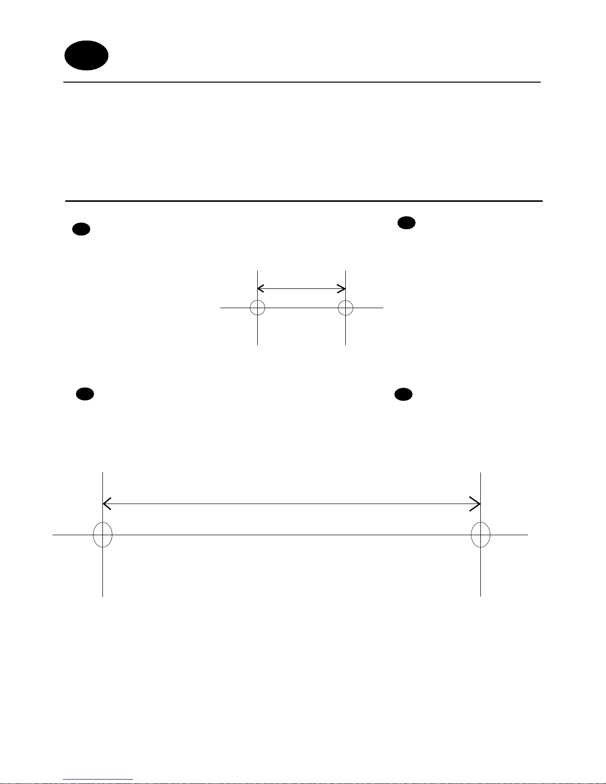
WALL MOUNT TEMPLATE / GABARIT DE MONTAGE MURAL
If you wish to wall mount the telephone ringer amplifier and the door bell, use
this template to mark the screw holes.
Utilisez ce gabarit pour marquer la position des trous sur votre mur si vous
désirez monter votre indicateur d’appel en position murale, ainsi que la
sonnette
SCREW HOLE CENTRES
FOR DOOR BELL
GB
SCREW HOLE CENTRES
FOR BASE
GB
ENTRAXE DE PERCAGE
POUR LA BASE
F
ENTRAXE DE PERCAGE
POUR LA SONNETTE
F
23.5 mm
101 mm
GB/F
 Loading...