

Page 1

ServO
2
Oxygen Control System
Operation, Maintenance &
Service Manual
S
erv
O
2
Oxygen Control System
%
Oxygen
(V/V)
™
+ -
Alarms
High
Defect
Low
Low
Sensor
Enable
Battery
Enable
%
Oxygen
Set
Incubator
Headbox
Calibrate
Page 2

User Responsibility
This Product will perform in conformity with the description thereof contained in this
operating manual and accompanying labels and/or inserts, when assembled, operated,
maintained and repaired in accordance with the instructions provided. This Product must
be checked periodically. A defective Product should not be used. Parts that are broken,
missing, plainly worn, distorted or contaminated should be replaced immediately. Should
such repair or replacement become necessary, Ohmeda recommends that a telephone or
written request for service advice be made to the nearest Ohmeda Regional Service
Center. This Product or any of its parts should not be repaired other than in accordance
with written instructions provided by Ohmeda and by Ohmeda trained personnel. The
Product must not be altered without the prior written approval of Ohmeda’s Quality
Assurance Department. The user of this Product shall have the sole responsibility for any
malfunction which results from improper use, faulty maintenance, improper repair, damage, or alteration by anyone other than Ohmeda.
CAUTION w U.S Federal and Canadian law restrict this device to sale by or on the order of a
licensed medical practitioner.
Page 3

Table of Contents
Table of Contents
General Precautions
Warnings........................................................................................................................ iii
Cautions..........................................................................................................................v
1/General Information
Introducing the ServO2 Oxygen Control System .........................................................1-1
Oxygen Environment ...................................................................................................1-1
Control Panel ...............................................................................................................1-2
Controls...............................................................................................................1-2
Displays...............................................................................................................1-3
Alarms .................................................................................................................1-3
Low Cell Indicator ........................................................................................................1-4
Operating Modes .........................................................................................................1-4
Mounting Options.........................................................................................................1-5
2/Operation
Preoperative Checkout Procedure...............................................................................2-1
Set-Up..........................................................................................................................2-2
Calibration....................................................................................................................2-3
Calibration Schedule ...........................................................................................2-3
Calibration Procedure .........................................................................................2-3
Using the ServO2 Oxygen Control System ..................................................................2-5
Incubator mounting bracket .........................................................................................2-6
Mounting the sensor............................................................................................2-6
Assembly.............................................................................................................2-7
Disassembly........................................................................................................2-8
3/Maintaining the ServO2 Oxygen Control System
Cleaning.......................................................................................................................3-1
4/Service procedures
4.1 Repair Policy..........................................................................................................4-2
4.2 Maintenance schedule..........................................................................................4-2
4.3 Troubleshooting .....................................................................................................4-3
4.4 Repair Procedures.................................................................................................4-4
4.5 Service Calibration...............................................................................................4-11
4.6 Service Checkout Procedure ...............................................................................4-14
i
6600-0241-000 06/30/97
i
Page 4

Table of Contents
5/Illustrated parts
Exterior parts ...............................................................................................................5-1
Base, manifold and solenoid parts...............................................................................5-2
Interior parts.................................................................................................................5-3
Sensor mounting bracket.............................................................................................5-4
Service Kits..................................................................................................................5-4
Complete units.............................................................................................................5-4
6/Schematics
Pneumatic diagram......................................................................................................6-1
Control board schematic..............................................................................................6-2
Control and PSU board layout .....................................................................................6-4
PSU board schematic ..................................................................................................6-5
Display board schematic..............................................................................................6-6
Display board layout ....................................................................................................6-7
Appendix
Warranty
Specifications.............................................................................................................. A-1
ii
6600-0241-000 06/30/97
ii
Page 5

General Precautions
Table of Contents
Definitions
What the attention symbol means
Next to each warning or caution, we have placed an “attention, readaccompanying
documents” symbol to alert you to the presence of these important statements. This is
the attention symbol:
w
When the attention symbol appears in front of text that is printed on the system itself, it
means that the text is elaborated upon in the operation manual.
WARNING: A Warning statement is used when the possibility of injury to the patient or
the operator exists.
CAUTION: A Caution statement is used when the possibility of damage to the equipment exists.
~ Indicates alternating current.
m Indicates IEC Type BF equipment.
Important: An Important statement is similar to a note but is used for greater emphasis.
Note: A Note provided additional information to clarify a point in the text.
The following are general Warnings and Cautions. Precautions specific to certain
procedures are found in the text of the manual.
w W arnings
Before using the ServO2 Oxygen Control System, read through this entire manual. As
with all medical equipment, attempting to use this device without a thorough understanding of its operation may result in patient or user injury.
Always disconnect the power and gas supplies before performing service or maintenance procedures detailed in this manual. Apply power only if you are specifically
instructed to do so as part of the procedure.
Indicates drip proof as stipulated in BS5724/IEC 601-1.
Indicates Class II equipment: earth connection not required for protection against
shock. Protection is provided by the inclusion of double and/or increased insulation.
When servicing use only identical replacement parts.
iii
6600-0241-000 06/30/97
iii
Page 6

General Precautions
Table of Contents
Oxygen concentrations higher than 40% can increase the risk of retrolental fibroplasia
(retinopathy of prematurity). It is probable that even concentrations of 40% or less
oxygen (formerly considered safe) could be dangerous to some infants. Therefore,
arterial blood gas measurements are extremely important for regulation of the concentration of inspired oxygen when an oxygen-enriched environment is considered necessary. (See current edition of “Standards and Recommendations for Hospital Care of
Newborn Infants” prepared by the Committee of Fetus and Newborn of the Academy of
Pediatrics.)
Complete the “Preoperative Check-out ” section of this manual before putting the unit
into operation. If the ServO2 Oxygen Control System fails any portion of the checkout
procedure it must be removed from use and repaired.
To prevent the possible depletion of the oxygen supply, disconnect the ServoO
Oxygen Control System from gas supplies when not in use.
Do not use the ServO2 Oxygen Control System in the presence of flammable anesthetics; an explosion hazard exists under these conditions.
Do not use oil bearing materials on or near the pneumatic parts of this unit. Oils and
grease oxidize readily, and in the presence of oxygen, they will burn violently. The air
or oxygen parts must be discarded if they are contaminated with oil or grease.
Fire hazard! Even material that will not normally burn will ignite readily and burn rapidly
in high concentrations of oxygen. Keep all sources of ignition away from the incubator
or headbox. Display “NO SMOKING” signs prominently.
Spontaneous and violent ignition may occur if oil, grease or greasy substances come in
contact with oxygen under pressure. Keep oil and grease away from regulators,
cylinder valves, tubing and connections, and all other oxygen equipment.
Use only approved reducing or regulating valves marked for oxygen service on high
pressure oxygen cylinders. Do not use valves for air or gases other than oxygen, since
they may be hazardous when returned to oxygen service. Operate all oxygen equipment strictly in accordance with the manufacturer’s directions.
High pressure oxygen and medical air equipment should always be located outside of
the nursery. Securely fix cylinders in place so that they can not be knocked over while
in use. Locate cylinders as far from the incubator or headbox as possible.
2
Use only equipment designed for use in hazardous locations in delivery rooms. Mixtures of oxygen and flammable vapors, such as alcohol, ether, ethylene and cyclopropane may explode if ignited. Electrical static spark discharges or high temperature
surfaces, in addition to all other more common sources of ignition, may ignite these
mixtures. Refer to Article 517 of the National Electrical Code, ANSI/NFPA 70, for the
use of flammable anesthetics.
iv
6600-0241-000 06/30/97
iv
Page 7

General Precautions
Table of Contents
w
Cautions
Only competent individuals trained in the repair of this equipment should attempt to
service it as detailed in the Manual.
Detailed information for more extensive repairs is included in the service manual solely
for the convenience of users having proper knowledge, tools and test equipment, and
for service representatives trained by Ohmeda.
Precautions specific to certain procedures are found in the text of the manual.
v
6600-0241-000 06/30/97
v
Page 8

Notes
Table of Contents
vi
6600-0241-000 06/30/97
vi
Page 9

1/General Information
In this section
Introducing the ServO2 Oxygen Control System ....................................................... 1-1
Oxygen environment.................................................................................................. 1-1
Control Panel ............................................................................................................. 1-2
Controls............................................................................................................. 1-2
Displays............................................................................................................. 1-3
Alarms ............................................................................................................... 1-3
Operating Modes............................................................................................... 1-4
Mounting options............................................................................................... 1-5
Introducing the ServO2 Oxygen Control System
The ServO2 oxygen control system controls a patient’s oxygen environment. By automatically changing the delivered gas ratio, it maintains the oxygen concentration level
set by the clinician.
A comprehensive series of alarms include high and low oxygen concentration, sensor
disconnected, short circuit or failure, battery running low and internal malfunction. The
system has two modes of operation which allow it to be used with both incubators and
head boxes.
Oxygen Environment
The ServO2 oxygen control system has a finite flow capacity. If the rate of escape from
the patient enclosure exceeds this flow, the unit will be unable to maintain the specified
concentration and will indicate a low oxygen alarm condition. Therefore sealing the
enclosure at high oxygen concentration levels is important.
When the enclosure is opened, oxygen concentration levels rapidly deplete. To react to
such a situation, the ServO2 system uses an oxygen boost system to quickly return the
environment to the specified level. The boost automatically turns on when demand is
highest, and turns off when the actual concentration level nears the specified level. (It is
important to point out that with the unit at its highest setting and the chamber leaking at
the greatest possible rate, it would take approximately 26 minutes to deplete a full Etype cylinder.)
In most cases, the ServO2 will control oxygen concentration levels within incubators or
similar large enclosures, and allows the nursing staff to dispense with headboxes. This
reduces the number of changes in oxygen concentration that the patient would experience with the removal of its headbox. It also improves O2 stabilization in headboxes/
beds when incubators are not available or clinically indicated.
1-1
6600-0241-000 06/30/97
1-1
Page 10
1/General Information
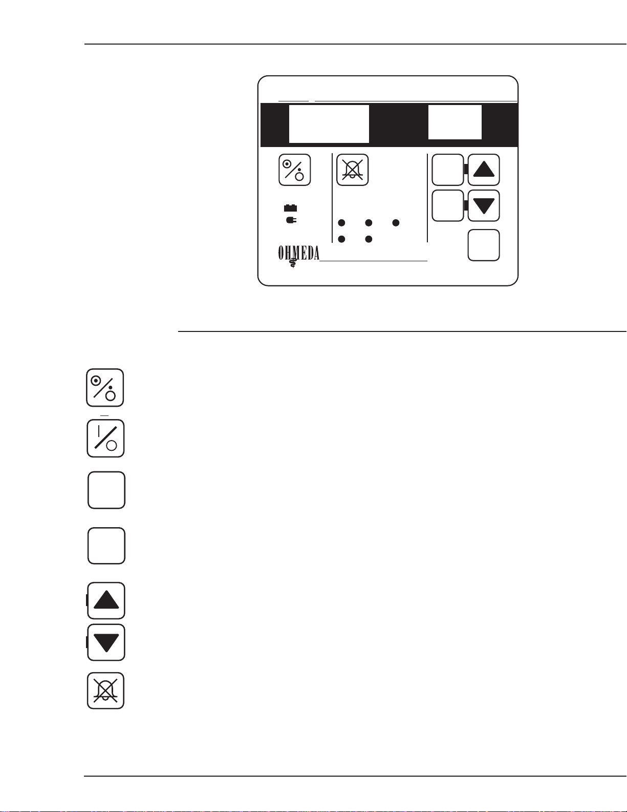
Control Panel
S
Figure 1-1
Control Panel
Oxygen Control System
erv
O
2
888
+ -
Alarms
High
Low
%
Oxygen
(V/V)
Defect
Sensor
Low
Battery
88
Enable
Enable
Calibrate
%
Oxygen
Set
Controls
On/Stand by button. Press to turn unit on. Press again to turn unit off. A short delay has
been set into the ‘off’ function to avoid inadvertent switch-off.
or
Enable
Calibrate
Note: The On/Stand by button does not control the electrical power supply. Whenever the
ServO2 system power cord is connected the internal battery is being charged.
Enable button. Used in conjunction with the M or ? buttons to change the required
oxygen concentration level.
Calibrate button. Used to check that the unit is within calibration. When the Calibrate
button is pressed, the ServO2 system automatically delivers 100% oxygen to the output
tube and the Oxygen Set display goes blank. You must press the Calibrate button and the
M or ? buttons to change the calibration setting.
M & ? buttons. Used with Calibrate and Enable buttons to change the calibration and
Oxygen Set point. Pressing the button changes the display by one digit. Holding the
button in continuously changes the display one digit at a time.
Alarm silence button. Cancels the audible alarm on High O2, Low O2, and Low Battery
alarms for a period of approximately 2 minutes, but the alarm indicator remains on.
Sensor and Defect alarms cannot be silenced.
1-2
At the end of the alarm silence period the audible alarm will automatically resume if the
alarm condition has not been resolved.
6600-0241-000 06/30/97
1-2
Page 11

1/General Information
Displays
% Oxygen (V/V) display. Three digit display indicates the actual oxygen concentration
%
Oxygen
level monitored by the oxygen sensor. This is displayed as a percentage of oxygen by
888
(V/V)
volume(v/v).
88
Alarms
High
Low
+ -
%
Oxygen
Set
Defect
Sensor
% Oxygen Set display. Two digit display indicates the required oxygen concentration
level set by the clinician. This is displayed as a percentage of oxygen by volume (v/v).
When the environment is stable the Oxygen Set and Oxygen V/V displays should be
within one digit of each other.
Battery indicator. When on indicates that the ServO2 system is running from its internal
battery.
Line indicator. When on indicates that the ServO2 system is using power from the wall
outlet. This is the normal mode of operation. This also indicates that the internal battery
is being automatically recharged.
Alarms
High alarm indicator. Actual Oxygen concentration level is greater than 3% (v/v) above
that displayed on Oxygen Set. Alarm condition immediately lights the High indicator on
the front panel. After a delay period of 2 minutes (nominal) an audible alarm sounds.
Both the visual indicator and audible alarm will automatically reset when the alarm
condition is resolved.
Low alarm indicator. Actual oxygen concentration level is greater than 3% (v/v) below that
displayed on Oxygen Set. Alarm condition immediately lights the Low indicator on the front
Low
panel. After a delay period of 2 minutes (nominal) an audible alarm sounds. Both the visual
Battery
indicator and audible alarm will automatically reset when the alarm condition is resolved.
Immediately following first pressing the On/Stand by button the Low audible alarm is
deactivated for approximately 2 minutes. This allows time for the gases to fill larger
chambers such as incubators, avoiding unnecessary alarms.
Sensor alarm indicator. The oxygen sensor is disconnected or there is an open or short
circuit in the sensor wiring. The indicator lights and the alarm sounds immediately, and
cannot be silenced. The % Oxygen display reads “00” and the oxygen solenoid is
automatically disabled.
Defect alarm indicator. Internal malfunction causes the indicator to light and the alarm to
sound immediately. This alarm cannot be silenced. Oxygen supply is automatically
disabled for safety purposes.
WARNING w Do not use the ServO2 Oxygen Control System if a Defect alarm is indi-
cated. The unit must be immediately removed from use and repaired.
Low Battery alarm indicator. Indicator lights immediately when the battery has only
7 minutes (nominal) remaining life. Delay of 2 minutes before the audible alarm sounds.
The audible alarm can be silenced.
1-3
6600-0241-000 06/30/97
1-3
Page 12
1/General Information
WARNING w If the low battery alarm remains unattended for a period of 7 minutes the
ServO2 Oxygen Control System will automatically turn itself off to prevent
permanent battery damage. The internal battery is provided as an emergency back-up only.
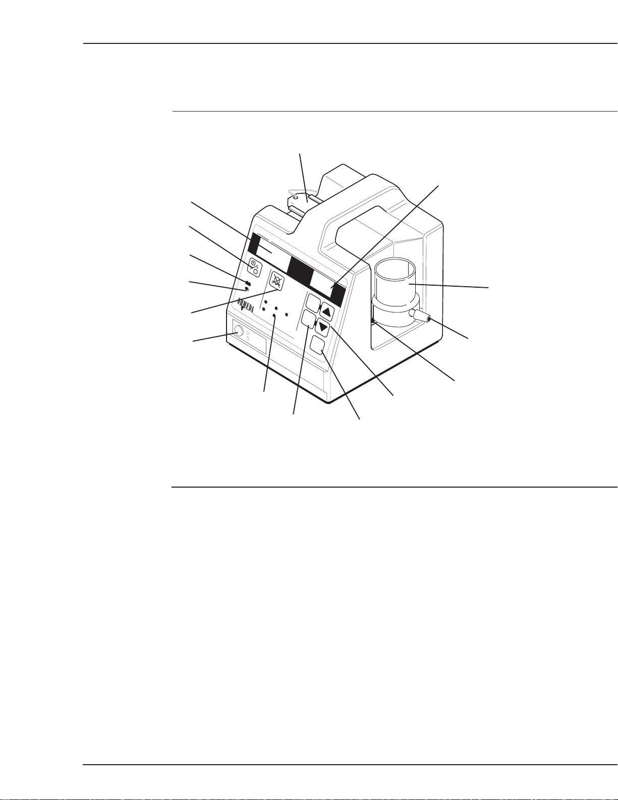
Mode key and holder
% Oxygen Set
Actual % Oxygen
On/Off button
Battery indicator
Line indicator
Alarm Silence button
Mode indicator
Figure 1-2
ServO2 Oxygen Control System front view
S
+ -
Incubator
Headbox
Alarm indicators
Enable buttons
erv
O
2
Oxygen Control System
Alarms
High
Low
%
Oxygen
(V/V)
%
Oxygen
Set
Defect
Sensor
Enable
Low
Enable
Battery
Calibrate
Calibration Port
Input barb connector
Sensor connector
% Oxygen control buttons
Calibrate button
Operating Modes
The ServO2 system can work in either Incubator or Headbox mode.
Incubator mode. To put the unit in Incubator mode press the metal switch on the back
of the unit (see Figure 1-3) and insert mode key into the slots . When connected to an
oxygen or air supply, the mode indicator on the lower left front of the unit will show a
series of red dots to indicate the Incubator mode.
Headbox mode. With the mode key removed (default) the unit is in low flow or
headbox mode. The mode indicator on the lower left front of the unit will show a series
of black dots (see Figure 1-2).
To put the unit back into Headbox mode simply remove the mode key. A holder located
on the top of the unit is provided for the safe storage of the mode key.
1-4
6600-0241-000 06/30/97
1-4
Page 13
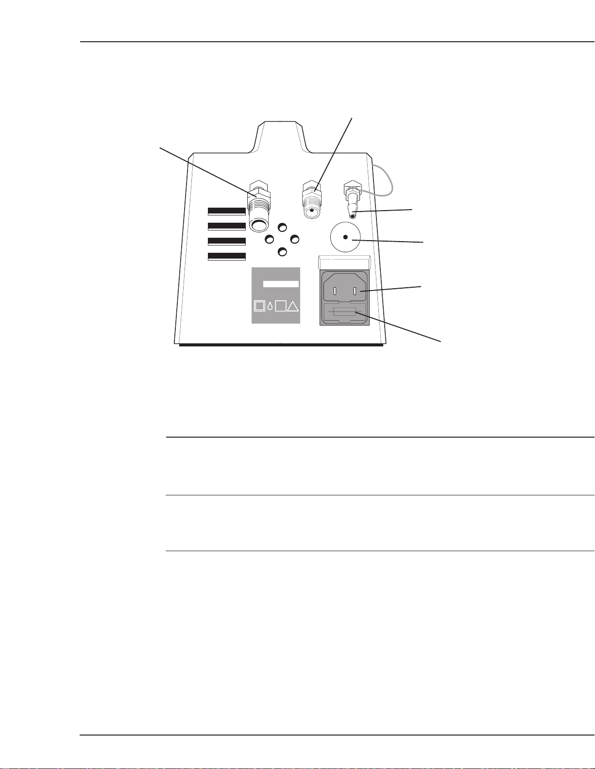
1/General Information
Medical air inlet
Oxygen inlet
Gas outlet
Headbox/Incubator switch
Power cord input
Fuse holder
Figure 1-3
ServO2 Oxygen Control System rear view
Mounting options
CAUTION w It is recommended that the ServO2 Oxygen Control System be used in con-
junction with a mounting bracket to prevent the unit from falling and being
damaged.
There are two mounting options available:
Dovetail mounting bracket (fits rails used on Ohmeda equipment) ......... 6600-0236-910
C-clamp/Universal rail mounting bracket (fits European style rails) ........ 6600-0236-913
1-5
6600-0241-000 06/30/97
1-5
Page 14

Notes
1/General Information
1-6
6600-0241-000 06/30/97
1-6
Page 15

2/Operation
WARNINGS w Do not perform the preoperative checkout procedure when the unit is
being used with a patient.
w Complete the “Preoperative Checkout ” section of this manual before
putting the unit into operation. If the ServO2 Oxygen Control System fails
any portion of the checkout procedure it must be removed from use and
repaired.
w Oxygen concentrations higher than 40% can increase the risk of
retrolental fibroplasia (retinopathy of prematurity). It is probable that even
concentrations of 40% or less oxygen (formerly considered safe) could be
dangerous to some infants. Therefore, arterial blood gas measurements
are extremely important for regulation of the concentration of inspired
oxygen when an oxygen-enriched environment is considered necessary.
(See current edition of “Standards and Recommendations for Hospital
Care of Newborn Infants” prepared by the Committee of Fetus and Newborn of the Academy of Pediatrics.)
w Do not use oil or oil bearing materials on or near the pneumatic parts of
this unit. Oils and grease oxidize readily, and in the presence of oxygen,
they will burn violently. The air and oxygen parts must be discarded if
they are contaminated with oil or grease.
In this section
Preoperative checkout Procedure ............................................................................. 2-1
Set-Up........................................................................................................................ 2-2
Calibration.................................................................................................................. 2-2
Calibration Schedule ......................................................................................... 2-2
Calibration Procedure ....................................................................................... 2-3
Using the ServO2 Oxygen Control System ................................................................ 2-3
Preoperative checkout procedure
1. Visually inspect the ServO2 Oxygen Control System, its power cord and sensor
cable for signs of damage.
2. Connect an oxygen supply to the unit, ensuring correct gas connection if no cross
connection system is in use such as DISS or NIST. Turn the unit on and check that
gas exhausts from the outlet barb on the back of the unit. Disconnect the oxygen
supply.
2-1
6600-0241-000 06/30/97
2-1
Page 16

2/Operation
3. Repeat step 2 with an air supply connected to the ServO2 Oxygen Control System.
4. Connect both gas supplies to the unit. Turn the unit on. Press the mode switch on
5. Disconnect the sensor to verify that the sensor indicator lights and that the alarm
6. Unplug the unit's power cord and verify that the battery indicator lights and that the
7. Calibrate the unit according to the instructions in Calibration in this section.
Set-up
1. Connect the Sensor cable to ServO2 Oxygen Control System.
2. Install the appropriate air and oxygen connections to the 1/8" NPT fittings on the
the back of the unit and check that the flow rate increases (there will be an audible
difference in sound level). When the mode switch is depressed and the unit is
connected to a gas supply, check that the mode indicator on the front of the unit
shows red dots.
sounds. Reconnect the sensor and verify the alarm is silenced and the indicator
goes out.
unit continues to function on battery power.
back of the unit.
3. Connect oxygen and air supplies to the inlets on the back of the unit (See Figure
1-3). Gas supplies greater than 65 PSI require high pressure ServO2 units (see
page 5-4 in section 5/Illustrated Parts).
4. Plug the power cord into the wall outlet. Check that the Line indicator is lit on the
front panel (See Figure 1-1).
5. Connect an appropriate length of tubing to the output connector at the rear of the
device (See Figure 1-3).
6. Place the unit within 6 feet (2 meters) of the incubator/cot to keep the sensor cable
from being strained.
CAUTION w It is recommend that the ServO2 Oxygen Control System be used in conjunction
with a mounting bracket to prevent the unit from falling and being damaged.
Calibration
Calibration Schedule
Calibrate the ServO2 system and its integral oxygen sensor according to the following
schedule:
• Before the equipment is first put into use.
2-2
• Before the equipment is used immediately following an extended period of storage.
• Once every 24 hours when the ServO2 system is in constant use.
6600-0241-000 06/30/97
2-2
Page 17

2/Operation
Calibration Procedure
1. Place oxygen sensor securely into the calibration port .
2. Fit the distal end of the ServO2 output hose (the end farthest away from the unit)
3. Press and hold the Calibrate button on the control panel. This will automatically
4. Allow approximately 20 seconds for the environment and sensor to stabilize.
5. While still pressing the Calibrate button, adjust the “% Oxygen (V/V)” display to
6. When the display stabilizes at 100%, release all the buttons. Remove the sensor
7. Remove the output hose from the calibration port input barb and place it in the
securely over the input barb connector on the calibration port.
blank out the “% Oxygen Set” display and deliver 100% Oxygen through the output
hose. Press and hold the Calibrate button throughout the calibration procedure.
read 100% by pressing the M or ? button. If it does not read 100%, the sensor
must be replaced.
from the port and place it in the ambient air. Check that the “% Oxygen (V/V)”
display reads 21% (± 1%). If it does not, the sensor must be replaced.
enclosure.
If a calibration port is not available the following is an alternative way to calibrate the unit.
1. Place oxygen sensor and the output tube from the ServO2 system together in a
small container such as a plastic bag.
CAUTION w Do not totally seal the container - excessive pressure may develop which can
lead to incorrect calibration. Always use the gas output from the ServO2 Oxygen Control System to calibrate the unit.
2. Press and hold the Calibration button on the front panel. This will automatically
blank out the % Oxygen Set display, and deliver 100% oxygen through the output
tube. Hold in the Calibration button throughout the calibration procedure.
3. Allow approximately 20 seconds for the environment and sensor to stabilize.
4. While still pressing the Calibration button, adjust the % Oxygen V/V display to read
100% by pressing either the M or ? button.
5. Release all buttons. Remove sensor from container and place in ambient air away
from the delivery tube. Check % Oxygen (v/v) display now reads 21% (±1%).
Note: If the display cannot be adjusted to reach 100% or does not return to 21%
(±1%), then the sensor must be replaced.
Using the ServO2 Oxygen Control System
WARNINGS w Fire hazard! Even material that will not normally burn will ignite readily
and burn rapidly in high concentrations of oxygen. Keep all sources of
ignition away from the incubator or headbox. Display “NO SMOKING”
signs prominently.
2-3
6600-0241-000 06/30/97
2-3
Page 18

2/Operation
WARNING w Spontaneous and violent ignition may occur if oil, grease of greasy
substances come in contact with oxygen under pressure. Keep oil and
grease away from regulators, cylinder valves, tubing and connections,
and all other oxygen equipment.
w Use only approved reducing or regulating valves marked for oxygen
service on high pressure oxygen cylinders. Do not use valves for air or
gases other than oxygen, since they may be hazardous when returned to
oxygen service. Operate all oxygen equipment strictly in accordance with
the manufacturer’s directions.
w High pressure oxygen and medical air equipment should always be
located outside of the nursery. Securely fix cylinders in place so that they
can not be knocked over while in use. Locate cylinders as far from the
incubator or headbox as possible.
w Use only equipment designed for use in hazardous locations in delivery
rooms. Mixtures of oxygen and flammable vapors, such as alcohol, ether,
ethylene and cyclopropane may explode if ignited. Electrical static spark
discharges or high temperature surfaces, in addition to all other more
common sources of ignition, may ignite these mixtures. Refer to Article
517 of the National Electrical Code, ANSI/NFPA 70, for the use of flammable anesthetics.
1. Set-up the unit as described in Set-up section.
2. Perform the Preoperative checkout procedure.
3. Check calibration according to the calibration procedure.
Note: Before use the ServO2 system can be checked by placing the sensor in air
and ensuring the oxygen (v/v) display reads 21% ±1%.
4. Place the unit in either the Incubator or Headbox Mode.
5. Place ServO2 system sensor in the patient chamber.
WARNING w Do not place the Oxygen Sensor so close that it might obstruct the pa-
tient airway, and do not obstruct or cover the end of the oxygen sensor
during use.
6. Place the output tube in the patient chamber. Direct gas flow away from both the
patient and the oxygen sensor. Using a deflecting device is recommended to
ensure good gas circulation when using a headbox or canopy.
7. For incubators, connect the delivery tube to the oxygen inlet on the incubator or
place it in the patient chamber so that it is in heated air flow coming up from within
incubator.
2-4
8. Turn unit on by pressing I/O button. A set point of 21% will be displayed.
9. Press and hold the Enable button and adjust the % Oxygen Set display to the
required oxygen concentration by pressing the M button. Release all buttons.
6600-0241-000 06/30/97
2-4
Page 19

2/Operation
10. The ServO2 Oxygen Control System will now adjust the delivered gas to correct the
difference between the oxygen concentration within the patient enclosure and the
required level set by the user.
Note: The ServO2 Oxygen Control System will easily control oxygen set point
concentrations in the Care Plus Incubator between 40 and 50%. However, in the
unlikely event that concentrations greater than 50% are desired, incubator conditions may prevent the ServO2 unit from achieving these levels. To reach these
higher set points use a headbox with the ServO2 unit in the headbox mode, or add
supplemental oxygen through the incubator’s oxygen inlet port and adjust the flow
rate as necessary.
2-5
6600-0241-000 06/30/97
2-5
Page 20

2/Operation
Notes
2-6
6600-0241-000 06/30/97
2-6
Page 21

3/Maintaining the ServO2 Oxygen Control System
Cleaning and Disinfection
The ServO2 Oxygen Control System has been specifically designed with chamfered
edges and a minimum of sharp corners to reduce dirt traps.
The ServO2 system can be cleaned by wiping down with a cloth and using a solution of
water and a mild detergent. Use Cavicide® disinfecting cleaner to disinfect the unit.
CAUTION w Do not autoclave or expose the ServO2 Oxygen Control System to tempera-
tures or humidity outside its specifications. Do not immerse any part of the
ServO2 system
.
3-1
6600-0241-000 06/30/97
3-1
Page 22

3/Maintaining the ServO2 Oxygen Control System
Notes
3-2
6600-0241-000 06/30/97
3-2
Page 23

4/Service Procedures
In this section
4.1 Repair Policy ..................................................................................................... 4-2
4.2 Maintenance schedule ...................................................................................... 4-2
Operator maintenance ...................................................................................... 4-2
Service maintenance......................................................................................... 4-2
4.3 Troubleshooting humidifier problems ................................................................ 4-3
4.4 Repair Procedures ............................................................................................ 4-4
A. Base Control/PSU Board Removal............................................................... 4-4
B. Display Board Replacement ......................................................................... 4-5
C. Touch Panel Replacement ........................................................................... 4-6
D. Transformer Chassis Replacement .............................................................. 4-7
E. Mains Fuse Replacement ............................................................................. 4-7
F. Manifold/Solenoid Assy Removal ................................................................ 4-7
G. Filter Replacement ....................................................................................... 4-7
H. Battery Replacement ................................................................................... 4-8
I. Input Sensor Cable replacement.................................................................... 4-8
J. Mode Indicator Replacement ........................................................................ 4-9
K. IEC Inlet Receptacle Replacement............................................................... 4-9
L. Speaker Replacement................................................................................. 4-10
M. Mode Selector Replacement...................................................................... 4-10
N. Air/Oxygen/Blend Swivel Replacement ...................................................... 4-11
O. Oxygen Sensor Cell Replacement ............................................................. 4-11
4.5 Service Calibration............................................................................................. 4-12
A. Calibration Set-up ....................................................................................... 4-12
B. Calibration Amplifier - Voltage Offset Null .................................................. 4-12
C. Digitally Controlled Variable Resistor ......................................................... 4-12
D. D to A Output Calibration............................................................................ 4-13
E. High/Low Alarm Calibration ........................................................................ 4-13
F. Display DVM Calibration ............................................................................. 4-14
G. Battery Charge Rate Set ............................................................................ 4-14
H. Battery Charge Current Check ................................................................... 4-14
I. Low Battery Alarm Threshold Calibration.................................................... 4-14
J. Calibration Re-assembly ............................................................................. 4-14
4.6 Service Checkout Procedure ............................................................................. 4-15
A. Gas Flow Rate Check................................................................................. 4-15
B. User Functions Check ................................................................................ 4-15
C. Alarm Check ............................................................................................... 4-16
D. Control Check............................................................................................. 4-17
E. Electrical Safety Test .................................................................................. 4-17
4-1
6600-0241-000 05/26/98
4-1
Page 24

4/Service Procedures
4.1 Repair Policy
Warranty repair and service must be performed by an Ohmeda Service and Distribution
Center. To contact an Ohmeda Service Representative, call the nearest Ohmeda
Service Center listed on the back cover.
Do not use malfunctioning equipment. Make all necessary repairs or have the equipment repaired by an Ohmeda Service and Distribution Center. Parts listed in the
manual, for this product, may be repaired or replaced by a competent, trained person
who has experience in repairing devices of this nature. After repair, perform all applicable check procedures described in the manual.
WARNING w Do not use oil or oil bearing materials on or near the pneumatic parts of
the unit. Oils and grease oxidize readily, and in the presence of oxygen,
they will burn violently. The air or oxygen parts must be discarded if they
are contaminated with oil and grease.
CAUTIONS w Only competent individuals trained in the repair of this equipment should
attempt to service it as detailed in the manual.
w Detailed information for more extensive repairs is included in the manual
solely for the convenience of users having proper knowledge, tools and test
equipment, and for service representatives trained by Ohmeda.
4.2 Maintenance schedule
The unit should be maintained in accordance with the procedures detailed in the
manual. Quarterly and yearly maintenance must be performed by a technically competent individual as described in the Repair Policy.
Operator maintenance
This schedule lists the minimum frequencies. Always follow hospital and local regulations for required frequencies.
Daily or before each patient Calibrate the ServO2 Oxygen Control System (see
Service maintenance
This schedule lists the minimum frequencies. Always follow hospital and local regulations for required frequencies.
Every six months Perform the service checkout and electrical safety
Every year Replace filters. Perform service calibration in this
section 2, Operation).
procedurein this section.
section
4-2
Every two years Replace the battery.
6600-0241-000 05/26/98
4-2
Page 25

4/Service Procedures
4.3 Troubleshooting ServO2 Oxygen Control System problems
Symptom Possible cause(s) Recommended action(s)
Oxygen display reads 00, Sensor cable is broken, Connect or replace the sensor cord
Sensor indicator on and disconnected or short circuit assembly
non-silencable alarm sounds
Defect indicator on and Electrical failure Remove unit from use
non-silencable alarm sounds or short circuit contact service
Setpoint can not Not pressing Enable Verify you press Enable
be adjusted and Mor ? at the same time and M or ? at the same time
Electronic fault Remove unit from use
contact service
ServO
system can not reach Sensor not in the patient Verify that the delivery tube and
2
and maintain the desired chamber or sensor is covered sensor are placed in the
setpoint Gas delivery tube is not patient chamber
in the patient chamber
Oxygen is not connected Check that the O
Oxygen and air lines Check connection
misconnected
Setpoint selected is too high Reset setpoint to a level that
for the enclosure being used. enables stabilization
system has a
ServO
2
maximum flow rate determined and/or
by the mode selected .
It can not compensate Limit leakage from incubator or
for leakage rates greater head hood.
than this.
`
Incubator door or portholes Close doors. If clinical procedures
left open too long require doors or porthole be open
Internal leak in unit Remove unit from service and check
Mode switch not fully engaged Remove mode key, make sure you
Check that tubing access
covers, porthole seals, incubator
controller seals, humidifier seals and
tray are in place and in good condition.
for extended periods, use head
box or porthole sleeves.
for leaks
press the switch button all the way in,
then re-insert mode key. If problem
persists, re-adjust switch
connection is secure
2
controller in wrong mode Change mode
ServO
2
Actual oxygen concentration Delivery tube output to close Re-position tube
level oscillates around set point to sensor
Can not calibrate at Sensor failure or depletion Replace sensor
100% oxygen
After calibration at 100% oxygen, sensor Defective sensor Replace sensor
does not display between 20 and 22%
Unit in incubator mode, but indicator Due to infrequent use With unit in incubator mode, and O2 at
shows Headbox mode or is not fully lubricant solidified 100%, pinch out tube to make back
in Incubator mode position pressure and free up indicator
4-3
6600-0241-000 05/26/98
4-3
Page 26

4/Service Procedures
4.4 Repair Procedures
WARNING w Before any disassembly or repair, disconnect the electrical and any gas
supply connections. Do not perform any service or maintenance with the
power applied unless specifically told to do so in the procedure.
w After each repair procedure, perform the service checkout procedure.
CAUTION s Use a Static Control Work Station (0175-2311-000) for all procedures marked with the
symbol s to help ensure static charges are safely conducted to the ground. The
Velostat material is conductive. Do not place electrically powered boards on it.
Important: In cases where total disassembly is not required, replacing only the touch
panel for example, perform only the necessary steps.
Wire Harness Table
harness board position wire colors
transformer secondary harness PL4 2 black wires
battery harness BATT 2 black & 2 red wires
speaker harness PL2 1 black, 1 red, 1 green, & 1
yellow wire
sensor input harness INPUT 1 red & 1 blue wire
display harness PL1 34 wire ribbon cable
solenoid harness PL3 6 red wires
Equipment needed:
Phillips screw driver #2
Small flat blade screwdriver
T-10 Torx driver (provided in service kit)
95° T-10 Torx driver (provided in service kit)
11mm socket wrench
8mm open end wrench
6mm open end wrench
Rubber gloves or two small sheets of rubber
1/4" dia. dowel rod
Wire cutters
50 - 60 psi (3 -4 bar) static gas pressure source
ss
s A. Base and Control/PSU board Removal
ss
(Refer to Figures 4-1 & 4-2)
1. Place the unit on its side with the oxygen sensor facing up and the base facing you.
2. Remove the six Phillips head mounting screws that secure the base to the case.
3. Remove base cover taking care not to stress tubing and cable attached to the mani-
fold/solenoid assembly attached to the base.
4-4
6600-0241-000 05/26/98
4-4
Page 27

4/Service Procedures
4. Remove the three color coded luer locks that attach the tubes to the manifold.
5. Press the release clip and slide the board partially out to gain access to wire
harness connectors.
Luer lock
clear/white
Mounting screw
Manifold
Base
black
blue
Calibrate
Solenoid harness
Battery
Low
Sensor
Defect
Low
High
+ -
Figure 4-1
Removing base
6. Disconnect the transformer secondary harness, the battery harness, the speaker
harness, the sensor input harness, the display ribbon cable and the solenoid
harness.
7. Remove the control/PSU board assembly.
Note: To disconnect the display ribbon cable use a small flat blade screwdriver.
Place the blade into the connector indexing slot and pry the connectors apart.
8. To separate the control board from the PSU board remove the four T10 Torx
screws that secure control board to the PSU board and separate the boards. Take
care not to excessively flex either board.
4-5
9. To replace either the PSU board or the control board, perform steps 1 through 8 in
reverse.
6600-0241-000 05/26/98
4-5
Page 28

4/Service Procedures
s s
s B. Display Board Replacement
s s
(Refer to Figure 4-2)
1. Remove the base and the control/PSU board assembly to gain access to display
board (see section 4.4A Base and Control/PSU assembly Removal).
Board release clip
PSU board
Control board
Display board
ribbon cable
Display board
Mode indicator
Transformer
Battery
O2 Sensor
cable cover
Ni Cad 7.2V/300mAHr
IEC receptacle insulating cover
Transformer chassis
Speaker
Air inlet
Oxygen inlet
Mode selector
Gas outlet
Figure 4-2
Interior view
2. Remove the transformer chassis.
3. Using a 95 degree T-10 Torx driver, remove the two mounting screws located at
the top of the display board.
4. Using a straight T-10 Torx driver, remove the two mounting screws located at the
bottom of the display board.
5. Disconnect touch panel ribbon cable from display board connector located on the
solder side of display board and carefully separate the display board from case.
6. To replace the display board, perform steps 1 through 5 in reverse.
s s
s C. Touch Panel Replacement
s s
1. Peel touch panel off the case.
Note: Prior to installation of a new touch panel, insure the case is clean for the
panel to properly adhere. It is important that the touch panel properly adheres to
the case to help protect the unit from spills.
2. Disconnect the ribbon cable from the touch panel.
4-6
6600-0241-000 05/26/98
4-6
Page 29

4/Service Procedures
3. Connect the ribbon cable to the new touch panel.
4. Apply new panel label to the case.
s D. Transformer Chassis Replacement
(Refer to Figure 4-2)
1. Remove the base and the control/PSU board assembly to gain access to the
transformer chassis (see section 4.4A Base and Control/PSU Board Removal).
2. To remove the A.C. mains wiring from the IEC inlet receptacle, slide the insulating
cover off the receptacle, remove the faston connectors, and remove the mains
wiring from the cover.
3. Remove the three T-10 Torx screw that hold the transformer chassis to the case,
and carefully remove the chassis from case.
4. To replace the transformer chassis, perform steps 1 through 3 in reverse.
E. Mains Fuse Replacement
1. Use a straight blade screw driver to pry off fuse cover from IEC receptacle located
on rear of unit (see Figure 1-3).
2. Replace the fuse with a fuse of the same rating.
ss
s F. Manifold/Solenoid Assembly Removal
ss
1. Remove the base and the control/PSU board assembly to gain access to the
manifold/solenoid assembly (see section 4.4A Base and Control/PSU Board
Removal).
2. Peel the service warning label off the bottom of base to expose the two mounting
screws on the outside of the base.
Note: A new label must be applied.
3. Remove the two Phillips head mounting screws that hold the manifold/solenoid
assembly to the base and remove the assembly.
4. Install the new manifold/solenoid assembly with the two Phillips screws removed in
step 3 and apply a new service warning label to the base.
5. Re-assemble the unit by reversing steps 1 through 7 in section 4.4A Base and
Control/PSU Board Removal.
ss
s G. Filter Replacement
ss
1. Remove the base and the control/PSU board assembly (see section 4.4A Base
and Control/PSU Board Removal).
4-7
6600-0241-000 05/26/98
4-7
Page 30

4/Service Procedures
2. Use a 11mm socket or box wrench to remove the black and the white plastic 1/8
NPT screws from the side of the manifold. Remove any debris from the filter
chambers before removing the filters. This can be done by directing high pressure
air into the chambers. Be sure to wear eye protection while using air pressure to
clean the filters.
3. To remove the two filters from within the manifold, lightly tap the manifold from the
reverse side or use a small curved pick.
4. Install new filters and re-install the black and the white plastic 1/8 NPT screws.
5. Re-assemble the unit by reversing the steps in section 4.4A Base and Control/PSU
Board Removal.
6. Install a new output barb.
7. Remove the NIST fittings and replace filters. When re-installing the fittings, use de-
greased PTFE tape (6600-0041-300) to seal them.
8. Perform service checkout procedure.
ss
s H. Battery Replacement
ss
(Refer to Figure 4-2)
1. Remove the base and the control/PSU board assembly to gain access to the
transformer chassis (see section 4.4A Base and Control/PSU Board Removal).
2. Remove the transformer chassis (see section 4.4D Transformer Chassis Removal).
3. Remove the two plastic knurled nuts that secure the battery and battery holder to
the transformer chassis.
4. Install the new battery and reverse steps 1 through 3 to re-assemble the unit.
ss
s I. Input Sensor Cable Replacement
ss
(Refer to Figure 4-2)
1. Remove the base and the control/PSU board assembly (see section 4.4A Base
and Control/PSU Board Removal).
2. Remove the black insulation from the case connector.
3. Remove the case connector and harness.
4. Slide the black housing off the wire and connector.
5. Remove the inlet connector and wire from the unit.
6. Install the new sensor cable.
4-8
7. Re-assemble the unit reversing steps 1 through 6.
6600-0241-000 05/26/98
4-8
Page 31

4/Service Procedures
J. Mode Indicator Replacement
1. Remove the base and the control/PSU board assembly (see section 4.4A Base
and Control/PSU Board Removal).
2. Disconnect the blue tubing from mode indicator.
3. Unscrew the 90 degree plastic tubing connector from the mode indicator.
4. Unscrew the black housing from the mode indicator.
5. Push on the rear of the mode indicator to loosen the label enough to peel it off.
Note: A new label must be installed.
6. Remove the mode indicator.
Note: Before installing a new mode indicator, clean the label area to ensure
adhesion of the new label.
7. Install a new mode indicator and label.
8. Re-assemble the unit by reversing the steps in section 4.4A Base and Control/
PSU Board Removal.
9. To adjust the mode selector switch:
a) Using a 1.5 mm hex key, remove the first of the two set screws in the hole in
the center of the switch.
b) While pushing the switch all the way in, adjust the second set screw until the
mode key locating groove aligns with the groove in the mode selector housing.
c) Re-install the first set screw to lock in the adjustment setting. Check that the
adjustment does not change.
d) Check that the mode key fits smoothly into the slot when the Incubator mode is
selected.
e) Check that when the mode key is in the slot there is no free play in the mode
selector (if there is, the selector switch may not have been pressed all the way
in when the adjustment was made).
ss
s K. IEC Inlet Receptacle Replacement
ss
(Refer to Figure 4-2)
1. Remove the base and the control/PSU board assembly (see section 4.4A Base
and Control/PSU Board Removal).
2. Slide the insulating cover off the back of the IEC receptacle.
3. Pull off the Faston connectors to disconnect the brown and blue wires from the IEC
receptacle.
4-9
4. Depress the locking tabs on both sides of the receptacle, and remove the receptacle.
5. Install the new receptacle. When re-installing the wiring, the brown wire is con-
nected to phase and the blue wire is connected to neutral. The neutral tab on the
receptacle is identified by an ‘N’ next to the connector.
6. Re-assemble the unit by reversing the steps in 4.4A Base Removal.
6600-0241-000 05/26/98
4-9
Page 32

4/Service Procedures
ss
s L. Speaker Replacement
ss
(Refer to Figure 4-2)
1. Remove the base and the control/PSU board assembly to gain access to the
speaker harness (see section 4.4A Base and Control/PSU Board Removal).
2. Disconnect the speaker harness.
3. Using a 95° T-10 Torx driver, loosen the screw that secures the speaker mounting
bracket and rotate the speaker mounting bracket.
4. Remove the speaker.
5. Install the new speaker, making sure the speaker seats in the top grooves.
6. Tighten the T-10 screw that holds the speaker mounting bracket in place.
7. Re-assemble the unit by reversing the steps in section 4.4A Base and Control/PSU
Board Removal).
ss
s M. Mode Selector Replacement
ss
1. Remove the base and the control/PSU board assembly (see section 4.4A Base
and Control/PSU Board Removal).
2. Remove IEC receptacle (see section 4.4K IEC Receptacle Replacement).
3. Remove transformer chassis (see section 4.4D Transformer Chassis Replacement).
4. Disconnect the tubing from the mode selector.
Note: Refer to the pneumatic circuit diagram in section 6 for installation of tubing.
5. Remove the tubing connector guard from the mode selector.
6. Using a 8mm open end wrench, remove the diverting valve assembly.
Note: Be careful not to damage the tubing connectors.
Note: The mounting hardware and selector knob are secured to the outside of the
case and do not need to be removed.
7. Install a new mode selector by reversing steps 4 through 6.
8. Re-assemble the unit reversing steps 1 through 3.
ss
s N. Air/Oxygen/Blend Swivel Replacement
ss
4-10
1. Remove the base and the control/PSU board assembly (see section 4.4A Base
and Control/PSU Board Removal).
2. Remove IEC receptacle (see section 4.4K IEC Receptacle Replacement).
3. Remove transformer chassis (see section 4.4D Transformer Chassis Replacement).
4. Using a 6mm open end wrench, remove the hose and hose connector from the
swivel mount.
6600-0241-000 05/26/98
4-10
Page 33

4/Service Procedures
5. Remove plastic swivel cap.
6. Remove the E-clip that holds the swivel to the case and remove the swivel.
7. Install new swivel by reversing steps 4 through 6.
Note: Be certain to re-install the plastic swivel connector.
Note: Do not over tighten the hose connector.
8. Re-assemble the unit reversing steps 1 through 3.
O. Oxygen Sensor Cell Replacement
1. To disconnect the oxygen sensor, grasp the connector located on the side of the unit
at its knurled sleeve. Slide the sleeve away from the unit and pull the connector out.
2. The sensor assembly has a friction fitted housing. There is a groove in the middle of
the housing where its two halves connect. To disassemble the housing, grasp the top
of the housing in one hand and the bottom in the other, then pull and snap the two
halves apart. Chemical residue or debris may cause the housing halves to stick, so it
may be necessary to twist the housing one quarter turn and pull the housing apart. If
the housing does not fully separate, twist a quarter turn in the reverse direction.
Continue twisting back and forth in quarter turns until the housing halves separate. It
may help to use rubber gloves or sheets of rubber to improve your grip. Using a tool
like a pliers or a wrench may damage the housing and is not recommended.
3. Disconnect the wires from the oxygen sensor cell: the blue wire is connected to the
center pin and the red wire is connected to the outer pin of the sensor.
4. The oxygen cell is a friction fitted assembly. To remove the oxygen cell, apply slight
pressure to the face of the cell. Chemical residue and debris may cause the
oxygen cell to stick. A 1/4" dia. dowel rod can be used to apply pressure to the
face. Do not use a sharp tool like a screw driver since it may damage the housing.
WARNING: w The sensor may release quickly. Do not direct the oxygen cell, dowel rod
and housing toward any person.
5. Install the new cell. Place the front of the sensor housing nose down on a firm
surface to avoid fracturing the housing while installing the O2 cell. Re-assemble
reversing steps 1 through 4.
ss
s 4.5 Service Calibration
ss
(Refer to Figure 4-3 for calibration test points)
Equipment needed:
Digital Voltmeter (mV resolution)
Display board IDC extension cable (provided in service kit)
Adjustable DC Voltage source ( 35mA min.)
Millivolt source (0 to 50mV) (provided in service kit)
Pot adjustment screwdriver
4-11
6600-0241-000 05/26/98
4-11
Page 34

4/Service Procedures
A. Calibration Setup
1. Remove the base and the control/PSU assembly according section 4.4A.
2. Lift the PSU board away from the control board. Electrically re-connect the PSU
board and control boards using the 14 pin extension cable. Note the polarity of the
connector; be sure that the red stripped wire is connected to the same pins. Rest
the Control and PSU boards on the bench next to the case.
3. Re-connect the ac supply (PL4) and the dc battery supply (BATT) to the PSU
board and the display board ribbon cable with the extension wire harness to the
display board. Note the polarity of the connector; be sure that the red stripped wire
is connected to the same pins.
4 . Connect the simulator to INPUT terminals on the control board. Set the switch on
the simulator to the down position. Re-connect the AC power cord. Switch on
ServO2 unit using the control panel button.
B. Calibration Amplifier - Voltage Offset Null
1. Using a voltmeter monitor between Test point 13 (TP13) and Test Pin 1 on the
Control board, short pins 2 and 3 of IC8.
2. Adjust VR1 on the control board until monitored voltage just flips between the
positive (+5V) and negative rails (-5V).
C. Digitally Controlled Variable Resistor
1. Using the control panel buttons (CAL & ?), set the user calibration setting to
minimum (ie, when the % Oxygen display settles at a value below which it will not
move).
2. Monitor TP1 with respect to TP13. Adjust the mV input until TP1 measures 1.000V.
3. Monitor TP2 with respect to TP13 without changing the mV input setting.
4. Adjust VR2 on control board until the voltage on TP2 is 0.500V
D. D to A Output Calibration
1. Adjust the control panel buttons (ENABLE and M) to display a setpoint of 50%.
2. Monitor TP4 with respect to TP13. Adjust VR5 until the voltage on TP4 is 1.000V
4-12
6600-0241-000 05/26/98
4-12
Page 35

4/Service Procedures
Fuse
F3
VR8
VR3
VR4
Battery
connector
BATT
Transformer
secondary
connector
PL4
VR5
Display
connector
PL1
Figure 4-3
Control/PSU board assembly test points
TP10
TP12
TP2
PL5
TP1
TP4
TP13
TP3
Note: This is a simplified board diagram.
For a more complete board layout see
section 6.
Sensor
connector
INPUT
IC8
Wiper
VR4(monitor point)
Speaker
connector
PL2
PL3
Solenoid
harness
VR2
VR1
E. High/Low Alarm Calibration
1. With the setpoint at 50%, check that TP4 is 1.000V.
2. Set the mV input so that TP3 is 1.000V with respect to TP13.
3. Monitor VR4 wiper (R47) with respect to TP13. Adjust VR4 until the monitored
voltage equals 0.600V.
4. Monitor the front display. Adjust the mV input slowly to check that the High and
Low alarms activate between 2 - 4% from the setpoint respectively.
F. Display DVM Calibration
1. Monitor TP3 with respect to TP13.
2. Using the control panel buttons (CAL and M) set user calibration to maximum.
3. Set mV input such that TP3 is 1.990V.
4. Adjust VR1 on Display board until ServO2's display just changes from 99 to 100
oxygen.
4-13
6600-0241-000 05/26/98
4-13
Page 36

4/Service Procedures
G. Battery Charge Rate Set
1. Monitor TP12 (power board PL6) with respect to TP13.
2. Ensure the battery is connected.
3. Adjust VR8 on the PSU board until TP12 is 9.20V.
H. Battery Charge Current check
Allow new batteries 5 minutes charge prior to performing this test. Monitor TP12 with
respect to TP10. With the battery connected and charging, the monitored voltage
should be in the range 0.37 and 0.76V (depending upon the battery terminal voltage). If
batteries fails check replace it.
I. Low Battery Alarm Threshold Calibration
1. Remove Secondary ac wire harness connector (PL4) and replace the battery dc
wire harness connector (BATT) with a variable dc power supply (minimum 35 mA
capacity).
2. Monitor this input voltage.
3. Adjust input voltage to 6.90V. Adjust VR3 on control board until Low Battery alarm
indicator just lights. Raise input voltage to 7.25V. The indicator should go out.
J. Calibration Re-assembly
Disconnect all test harnesses and re-assemble unit performing steps 1 through 3 of
4.5A Calibration Set Up in reverse.
4.6 Service Checkout Procedure
Equipment needed:
Calibration port
Medical air and oxygen supply 50 -60 PSI (3-4 bar)
Graduated flowmeter 0 to 20 lpm
Oxygen bubble tubing (or equivalent)
Incubator/Headbox/Electronic Load Simulator (provided in the service kit)
The ServO2 system incorporates a pneumatic switch, accessible by the user, to shift
from Incubator (high flow) to Headbox (low flow) mode as necessary.
Connect electrical mains and gas supplies to the ServO2 unit.
4-14
6600-0241-000 05/26/98
4-14
Page 37

4/Service Procedures
A. Gas Flow Rate Check
Note: To achieve the output flow rate specified in the appendix, this flow rate check
requires a pressure of 3.99 bar for both medical air and oxygen supplies.
1. Connect a graduated flowmeter to the output connector of the ServO2 unit using
the bubble tubing.
2. Switch the ServO2 unit on using the control panel button.
3. Set the ServO2 unit for the Incubator mode.
4. Adjust the setpoint to 22 % and place the sensor in ambient air (ie, reading 21%).
5. Remove the medical air gas supply and check that the flow rate indicated by the
flowmeter reads between 12 and 15 lpm while the oxygen solenoid valve is open.
Note: For the Headbox mode the normal oxygen and air flow rates are between 5
and 7 lpm; the auxiliary oxygen solenoid has no appreciable affect.
6. Increase the setpoint to >24% to open the auxiliary oxygen solenoid valve and
check that the flow rate reads between 17 and 20 lpm.
7. Remove the oxygen gas supply and re-connect the medical air gas supply.
8. With the setpoint adjusted to 21% and the user calibration set such that the actual
oxygen display reads >22%, check that the flowmeter reads between 12 and 15
lpm while the air solenoid valve is open.
9. Re-connect the oxygen gas supply.
B. User Functions Check
1. Place oxygen sensor securely into the calibration port.
2. Fit the distal end of the ServO2 out put hose (the end farthest away from the unit)
securely over the input barb connector on the calibration port.
3. Press the Calibrate button on the control panel. This will automatically blank out the
“% Oxygen Set” display and deliver 100% Oxygen through the output hose. Press
and hold the Calibrate button throughout the calibration procedure.
4. Allow approximately 20 seconds for the environment and the sensor to stabilize.
5. While still pressing the Calibrate button, adjust the “% Oxygen (V/V)” display to
read 100% by pressing the M or ? button. If it does not read 100%, the sensor
must be replaced.
6. When the display stabilizes at 100%, release all the buttons. Remove the sensor
from the port and place it in ambient air. Check that the “% Oxygen (V/V)” display
reads 21% (± 1%). If it does not, the sensor must be replaced.
4-15
6600-0241-000 05/26/98
4-15
Page 38

4/Service Procedures
C. Alarm Check
1. Disconnect the sensor cable and check that the Sensor alarm indicator lights and
audible alarm sounds immediately.
2. Check that the alarm can not be silenced by pushing the alarm silence button.
3. Re-connect the sensor cable assembly.
4. Using blended output fed directly back to the sensor, simulate and maintain a high
Oxygen condition (3% above setpoint).
5. Check that the High alarm indicator lights immediately and that after 2 minutes the
audible alarm sounds.
6. Check that this alarm can be silenced by pushing the alarm silence button.
7. Disconnect gas supplies.
8. Increase the setpoint to simulate a Low oxygen alarm condition (3% below
setpoint).
9. Check that the Low alarm indicator lights immediately and that after 2 minutes (±
10 seconds) the audible alarm sounds.
10. Check that the alarm can be silenced by pushing the alarm silence button.
Note: Before performing the battery life test, connect the ServO2 unit to a mains
electrical supply for 24 hour to ensure that the battery is fully charged.
11. With setpoint at 21% and sensor in ambient air (ie, reading 21%) the Normal Air
and Oxygen solenoids will begin to cycle. Unplug the unit and check that the it
continues to run on battery with no corruption of displays during the change-over
period.
12. Leave the unit running until the Low Battery alarm indicator lights. If the battery
does not operate for at least 60 minutes it should be replaced.
13. Using the alarm silence button, silence the alarm after it sounds.
14. Check the unit turns itself off at least 6 minutes after the indicator comes on.
15. Re-charge the battery before putting the unit back in service.
4-16
6600-0241-000 05/26/98
4-16
Page 39

4/Service Procedures
D. Control Check
The control check can be done either by setting up the ServO2 unit to control oxygen in
an incubator, or by using an electronic load simulator. This dummy load simulates an
input to the ServO2 unit and is affected by the ServO2 unit’s electrical output. The
simulator allows testing to be completed on the bench.
Incubator
1. Connect the gas supplies, electrical mains supply and gas output tube to the
ServO2 unit.
2. Connect the gas output tube from the ServO2 unit to the incubator.
3. Place the sensor on the incubator mattress.
4. Switch the unit on using the I/O control panel button and adjust setpoint to 40%.
5. Check that the ServO2 unit controls the incubator to within ± 1% of setpoint.
Note: The incubator should be operating to ensure good gas circulation.
Electronic Load Simulator
1. Connect the load simulator to the INPUT connector on the Control board and the
Solenoid connector on the PSU board (PL3).
2. Adjust setpoint to 50%.
3. Check that unit controls within ± 1% of setpoint.
E. Electrical Safety Check
Enclosure leakage current
Use approved equipment and techniques to test the unit’s enclosure leakage current.
Follow the directions supplied by the test equipment manufacturer to verify the following:
1. Normal condition: Less than 100 microamperes*.
2. Single fault condition (interruption of one supply conductor): Less than 300 microamperes*.
* Tested as a double insulated device with an insulated enclosure.
4-17
6600-0241-000 05/26/98
4-17
Page 40

4/Service Procedures
Notes
4-18
6600-0241-000 05/26/98
4-18
Page 41

5/Illustrated Parts
4
S
erv
O
2
Oxygen Control System
3
+ -
Incubator
Headbox
%
Oxygen
(V/V)
%
Alarms
High
Defect
Low
Low
Sensor
Battery
Oxygen
Set
Enable
Enable
Calibrate
2
Back
6
8
1
7
Figure 5-1
5
Exterior parts
5-1
Item stock number
1. Incubator/headbox label................................................6600-0696-223
2. Calibration port..............................................................6600-0696-246
3. Membrane switch panel ................................................6600-0696-230
4. Mode key with cord .......................................................6600-0696-225
5. Fuse ..............................................................................6600-0696-237
6. Swivel elbow, air
(includes cover, DISS connector and barb) ..................6600-0696-204
(includes cover, NISTconnector and barb)....................6600-0696-253
7. Swivel elbow, O
2
(includes cover, DISS connector and barb) ..................6600-0696-205
(includes cover, NIST connector and barb)...................6600-0696-254
8. Swivel elbow, blend (includes cover and barb) ............6600-0696-206
Parts not shown
Label kit (complete).......................................................6600-0696-224
Rubber feet (four)..........................................................6600-0696-229
Power cord, 240V..........................................................6600-0696-235
Sensor cable(with out sensor).......................................6600-0696-242
O2 Sensor .....................................................................6600-0696-209
6600-0241-000 06/30/97
5-1
Page 42

5/Illustrated Parts
1
2
Calibrate
Battery
Low
Sensor
Defect
Low
High
+ -
Figure 5-2
Base, manifold and solenoid parts
Item stock number
1. Manifold/solenoid assembly with valves & label ...........6600-0696-201
2. Case base (includes label and 4 rubber feet) ...............6600-0696-219
Not shown
Manifold fittings kit (inludes male & female luer,
1/8 NPT black plug, 1/8 NPT white plug,
& two10-32 UNF plugs).................................................6600-0696-203
5-2
6600-0241-000 06/30/97
5-2
Page 43

5/Illustrated Parts
11
12
6
7
8
1
Ni Cad 7.2V/300mAHr
5
4
3
10
2
9
Figure 5-3
Interior parts
Item stock number
1. Mode indicator (includes cover and barb) .....................6600-0696-207
2. Mode switch kit (includes actuator, valve and cover)....6600-0696-208
3. Battery kit (includes wire harness & holder)..................6600-0696-216
4. Transformer mounting chassis......................................6600-0696-220
5. Transformer, 110V (includes wire harness) ..................6600-0696-239
Transformer, 220V (includes wire harness) ..................6600-0696-240
6. PCB, PSU .....................................................................6600-0696-231
7. PCB, control board........................................................6600-0696-232
8. PCB, display board .......................................................6600-0696-233
9. IEC inlet receptacle with insulation cover......................6600-0696-234
10. Speaker (includes wire harness) ...................................6600-0696-238
11. Sensor cable assembly (internal) ..................................6600-0696-241
12. Insulating board assy. ...................................................6600-0696-221
5-3
6600-0241-000 06/30/97
5-3
Page 44

5/Illustrated Parts
Service Kits
Item stock number
Maintenance kit (includes outbarb assembly
and 4 sintered filters)................................................................ 6600-0696-210
Service Kit (includes tape, load simulator,
50 mV source, 14 pin extension cable, display
and Control/PSU board extension cable and
Torx driver set) ......................................................................... 6600-0696-211
Pneumatic tubing kit (with assembled
barbs and fittings)..................................................................... 6600-0696-202
Teflon tape (PTFE) de-greased ............................................... 6600-0696-212
Clip kit (includes metal speaker clip, PCB Clip,
Mode key holder, & swivel elbow circlip).................................. 6600-0696-226
PCB mounting kit (includes spacers and bracket) ................... 6600-0696-227
Hardware kit (includes all screws)............................................ 6600-0696-228
Air High Pressure Regulator Kit (includes regulator,
regulator holder, tubing and barbs) ......................................... 6600-0696-243
O2 High Pressure Regulator Kit (includes regulator,
regulator holder, tubing and barbs) ......................................... 6600-0696-244
Complete Units
ServO2 Oxygen Control System (100-120V, DISS, Canada) .. 6600-0236-902
ServO2 Oxygen Control System (100-120V, DISS, Export) .... 6600-0236-903
ServO2 Oxygen Control System (100-120V, NIST, Export)..... 6600-0236-907
ServO2 Oxygen Control System (220-240V, NIST, Export)..... 6600-0236-904
ServO2 Oxygen Control System (220-240V, DISS, Export) .... 6600-0236-908
ServO2 Oxygen Control System,
high pressure (100-120V, DISS, Export).................................. 6600-0236-905
ServO2 Oxygen Control System,
high pressure (220-240V, NIST, Export).................................. 6600-0236-906
5-4
6600-0241-000 06/30/97
5-4
Page 45

6/Schematics
✽
Manifold
O
2
M.A.
clear/white tubing
black tubing
blue tubing
Flow restrictor
✽
blue connector
Mode
Selector
Mode Indicator
CI.21.016
6-1
Valve present on high pressure units only
✽
Figure 6-1
Pneumatic diagram
6600-0241-000 06/30/97
6-1
Page 46
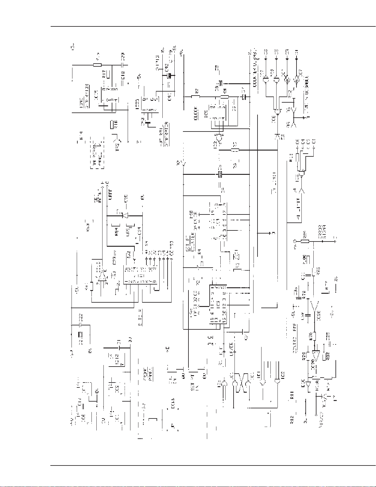
6/Schematics
CI.21.017
6-2
Figure 6-2
Control Board Schematic (part 1)
6600-0241-000 06/30/97
6-2
Page 47
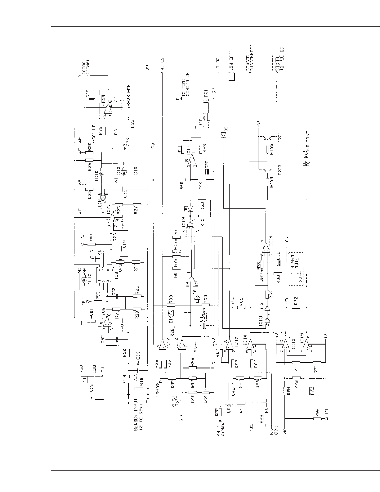
6/Schematics
CI.21.018
6-3
Figure 6-3
Control Board Schematic (part 2)
6600-0241-000 06/30/97
6-3
Page 48

6/Schematics
CI.21.019CI.21.020
Note: Capacitors C51 and C52
connected on the other side of
the control board.
6-4
Figure 6-4
Control Board and PSU Board layout
6600-0241-000 06/30/97
6-4
Page 49

6/Schematics
CI.21.021
6-5
Figure 6-5
PSU Board Schematic
6600-0241-000 06/30/97
6-5
Page 50

6/Schematics
CI.21.022
6-6
Figure 6-6
Display Board Schematic
6600-0241-000 06/30/97
6-6
Page 51

6/Schematics
6-7
Figure 6-7
Display Board Layout
6600-0241-000 06/30/97
CI.21.023
6-7
Page 52

Notes
6/Schematics
6-8
6600-0241-000 06/30/97
6-8
Page 53

Appendix
In this section
Specifications
All specifications are subject to change without notice.
Specifications
Electrical:
Mains Supply Voltage: 100-120Vac (±10%)
Mains Supply Frequency: 50/60Hz
Power Consumption: 5VA
Mains Fuse: 20mm, 250V,50mA, Antisurge
Internal Battery: 7.2V 300 mAhr Nickel Cadmium Rechargeable
Battery Life: 1 hr (nominal) from full charge
Battery Charge Time: 24 hours from total discharge
Electrical
Gas
Environmental
Saftey
Sensor
Alarms
Accuracy
Physical
220-240Vac (±10%)
Gas
Oxygen Supply Pressure: 3 to 4.5 Bar (42 to 65 PSI)
High Pressure unit - 4.5 to 10 Bar (65 to 145 PSI)
Medical Air Supply Pressure: 3 to 4.5 Bar (42 to 65 PSI)
High Pressure unit - 4.5 to 10 Bar (65 to 145 PSI)
Output Flow: Incubator mode minimum 12 lpm; 17 lpm (boost) at 3.99 bar
Headbox mode minimum 5 lpm (no boost) at 3.99 bar
Environmental
Temperature: +10 to +57° Celsius
Humidity: 0 to 95% RH
Pressue Range: 500 to 1060 hPa
Environmental (non operating)
Temperature –12° to +57° Celsius
Safety
Drip Proof: enclosure designed to prevent the ingress of fluids under
vertically falling conditions as stipulated by BS5724/IEC 601-1
m
Type BF equipment: sensor and delivery tube are floating applied parts.
A-1
6600-0241-000 05/26/98
A-1
Page 54

Appendix
Class II equipment: Earth connection not required for protection against
electric shock. Protection is privided by the inclusion of double and/or
increased insulation. When servicing use only identical replacement parts.
Mode of operation: Continuous
Electromagnetic
Compatibility: Meets the requirements of IEC 601-1-2
Enlosure Normal condition: Less than 100 microamperes
Leakage currents Single fault condition (interuption of one supply
conductor) : Less than 300 microamperes.
Sensor
Sensor Type: Ohmeda Fuel Cell part no. 6600-0696-209
Humidity: 0-100% RH Non Condensing
Expected Life: 425 000% O2 hours (6 months @ 100% O2; 23°C)
Response: 90% in less than 15 seconds
Alarms
High Oxygen Fixed 3% (v/v) above setpoint
Low Oxygen Fixed 3% (v/v) below setpoint
Low Battery Nominal 7 minutes battery life remaining
Sensor Sensor disconnect, short circuit or open circuit
Defect Internal electronic malfunction
Manual Audible Alarm Silence Nominal 2 mins. Reset upon subsequent depression
Automatic High/Low O2 Silence 2 min (nom) from visual alarm
Audible alarm frequency less than 1KHz
power min. 65 dB @ 1 meter
Accuracy
Control Accuracy: ± 1% (v/v) from setpoint
Display Accuracy: ± 2% (v/v) of actual value. Accuracy maintained for a
minimum of 24 hours following user calibration.
Alarm Setpoint: ±1 % (v/v) from alarm setpoint
Display Range: 0% (v/v) to 100% (v/v) oxygen concentration
Setpoint Range: 21% (v/v) to 90 % (v/v) oxygen concentration
Physical
A-2
Height: 165 mm (6.5 in)
Width: 140 mm (5.5 in)
Depth: 152 mm (6.0 in)
Weight: 1.9 kg (4 lb 3 oz)
6600-0241-000 05/26/98
A-2
Page 55

Warranty
Appendix
his Product is sold by Ohmeda under the warranties set forth in the following paragraphs. Such warranties are extended only with respect to the purchase of this Product
directly from Ohmeda or Ohmeda’s Authorized Dealers as new merchandise and are
extended to the Buyer thereof, other than for the purpose of resale.
For a period of twelve (12) months from the date of original delivery to Buyer or to
Buyer’s order, but in no event for a period of more than two years from the date of
original delivery by Ohmeda to an Ohmeda Authorized Dealer, this Product, other than
its expendable parts, is warranted to be free from functional defects in materials and
workmanship and to conform to the description of the Product contained in this operation manual and accompanying labels and/or inserts, provided that the same is properly
operated under the conditions of normal use, that regular periodic maintenance and
service is performed and that replacements and repairs are made in accordance with
the instructions provided. This same warranty is made for a period of thirty (30) days
with respect to expendable parts. The foregoing warranties shall not apply if the
Product has been repaired other than by Ohmeda or in accordance with written instructions provided by Ohmeda, or altered by anyone other than Ohmeda, or if the Product
has been subject to abuse, misuse, negligence, or accident.
Ohmeda’s sole and exclusive obligation and Buyer’s sole and exclusive remedy under
the above warranties is limited to repairing or replacing, free of charge, at Ohmeda’s
option, a Product, which is telephonically reported to the nearest Ohmeda Regional
Service Office and which, if so advised by Ohmeda, is thereafter returned with a
statement of the observed deficiency, not later than seven (7) days after the expiration
date of the applicable warranty, to the designated Ohmeda Service Center during
normal business hours, transportation charges prepaid, and which, upon Ohmeda’s
examination, is found not to conform with above warranties. Ohmeda
otherwise liable for any damages including but not limited to incidental damages,
consequential damages, or special damages.
shall not be
There are no express or implied warranties which extend beyond the warranties
hereinabove set forth.
particular purpose with respect to the product or parts thereof.
Ohmeda
makes no warranty of merchantability or fitness for a
A-3
6600-0241-000 05/26/98
A-3
W-1
Page 56

Ohmeda Inc
9065 Guilford Road
Columbia MD 21046-1801
USA
http://www.ohmeda.com
North America
United States
USA Customer Service
Ohmeda Inc
Ohmeda Drive
PO Box 7550
Madison WI 53707-7550
Tel 800 345 2700
Fax 608 221 4384
USA Technical Support
Ohmeda Inc
Ohmeda Drive
PO Box 7550
Madison WI 53707-7550
Tel 800 345 2755
Fax 608 223 2474
USA Service and
Distribution Center
Ohmeda Inc
7750 The Bluffs NW
Austell GA 30168-7754
Tel 800 345 2755
Tel 770 739 4774
Fax 770 739 4770
Canada
Customer Service and
Service Center
Ohmeda
5975 Falbourne Street Unit 2
Mississauga Ontario
Canada
L5R 3W6
Tel 905 568 9533
Fax 905 568 9799
Telex 06989362
Asia/Pacific
India
Ohmeda
B.O.C. India Ltd
Oxygen House
P43 Taratala Road
Calcutta 700 088
India
Tel 91 33 478 4342
Fax 91 33 478 4410
Japan
Ohmeda Ltd.
No. 21 Maru Ya Bldg.
2-6-11 Kaname-cho Toshima-ku
Tokyo 171 Japan
Tel: 81-3-3973-4055
Fax: 81-3-3973-9102
Malaysia
Ohmeda
Malaysian Oxygen Berhad
13 Jalan 222
46100 Petaling Jaya
Selangor
Malaysia
Tel 60 3 755 4233
Fax 60 3 756 6389
Singapore
Ohmeda Pte Ltd
198 Yishun Avenue 7
Singapore 768926
Tel 65 753 6311
Fax 65 753 1817
Australia
Ohmeda
Units 1 & 2
149 Arthur Street
P O Box 356
Homebush
NSW 2140
Australia
Tel 61 132 229
Fax 61 297 461796
Europe
Austria
Ohmeda Austria GmbH
Am Concorde Park E1 / 7
A - 2320 Schwechat
Austria
Tel 43 1 706 36 60
Fax 43 1 706 36 60 - 11
Belgium
Ohmeda
Divisie van BOC NV
Maaltecenter Blok G
Derbystraat 251
9051 Gent
Tel 32 9 220 4757
Fax 32 9 221 8541
Denmark
BOC Ohmeda A/S
Carl Gustavs Gade 3
Høje-Taastrup
DK-2630 Taastrup
Denmark
Tel 45 43 71 43 72
Fax 45 43 71 72 71
Finland
BOC Ohmeda Oy
PL 78 Kuunkehrä 2 B
02211 Espoo
Finland
Tel 358 9 803 73 44
Fax 358 9 803 05 69
France
Ohmeda
Parc De Pissaloup
8 Avenue Jean D’Alembert
78191 Trappes-Cedex
France
Tel 33 1 30 68 60 00
Fax 33 1 30 68 60 01
Germany
Ohmeda GmbH & co.KG
Langemarckplatz 3
D 91054 Erlangen
Germany
Tel 49 91 31 81 01 10
Fax 49 91 31 81 01 77
Italy
Ohmeda
Via Carpaccio 33
20090 Trezzano sul Naviglio
Milan
Italy
Tel 39 2 445761
Fax 39 2 48403233
Telex 314479 I
Netherlands
Ohmeda BV
Rembrandtlaan la
3723 BG Bilthoven
Netherlands
Tel 31 30 2289 289
Fax 31 30 2288 366
Spain
Ohmeda
C/Manuel Tovar 26
28034 Madrid
Spain
Tel 34 1 334 26 00
Fax 34 1 358 12 84
Sweden
BOC Ohmeda AB
Nordic
PO Box 631
Östra Sandgatan 12
S 251 06 Helsingborg
Sweden
Tel 46 42 17 87 40
Fax 46 42 17 87 47
United Kingdom
Ohmeda
Ohmeda House
71 Great North Road
Hatfield Hertfordshire
AL9 5EN England
Tel 44 1707 263570
Fax 44 1707 260191
Telex 915128
Latin America,
Caribbean
Latin America
Ohmeda
9200 Dadeland Boulevard
Suite 610
Miami FL 33156
USA
Tel 305 670 9938
Fax 305 670 4834
Middle East
Dubai
Ohmeda
Middle East Operations
P O Box 5527
Dubai
United Arab Emirates
Tel 97 14 822653
Fax 97 14 822659
6600 0241 000
05 98 D 13 10 06
Printed in USA
© Ohmeda Inc
 Loading...