

Page 1
®
OEC
W orkstation
Illustrated Par ts Manual
00-881713-01
Contents Installation Service Schematics Periodic Maintenance Illustrated Parts
Page 2

Workstation Illustrated Parts Manual
This manual may not be reproduced in whole or in part, without written permission of GE OEC Medical Systems,
Inc.
The contents of this document are accurate at the time of publication. However, changes in design and additional
features can, at any time, be incor porated in the hardware and software and may not be reflected in this version of
the document. Contact GE OEC Technical Support for clarification, if discrepancies arise.
OEC and OEC 9800 are registered trademarks of GE OEC Medical Systems, Inc. Other products and company
names mentioned herein are the property of their respective owners.
The OEC Workstation is manufactured under the following U. S. Patents: 5,596, 228; 08/ 209,001; 5, 426,683;
5,506,882; 5,583, 909; 4, 797,907; 07/ 638, 176.
Other U.S. and foreign patents pending.
Made in the U.S.A.
2OEC
© 1999, 2000
GE OEC Medical Systems, Inc.
384 Wright Brothers Drive
Salt Lake City, Utah 84116
U.S.A.
All rights reserved
Contents Installation Service Schematics Periodic Maintenance Illustrated Parts
Page 3

Workstation Illustrated Parts Manual
Introduction
Purpose
This manual contains information on the OEC Workstation. It serves as an aid to field service engineers and
technicians in locating parts and identifying part numbers. It is not a complete parts list and should not be used as a
substitute for a bill of materials.
NOTE: The item numbers on the illustrations do not match the item numbers on the assembly drawings or the
item numbers on the Bills of Materials.
Intended Audience
This manual is intended for the properly trained engineer or technician who designs, installs, maintains or calibrates
the OEC Workstation.
Removing or installing parts should not be attempted by anyone who is not specifically trained by GE OEC Medical
Systems, Inc.
3OEC
How to Use this Manual
This manual is formatted and intened for CD distribution. This manual is organized using navigation screens. Click
on the section of interest and then refer to the table of contents on the front page to locate the information you
require.
Contents Installation Service Schematics Periodic Maintenance Illustrated Parts
Page 4

Workstation Illustrated Parts Manual
Manual Revision History
Rev Dash Date Change Description
A -01 September, 1999 Manufacturing Release
B -01 December, 2000 Format changes.
4OEC
Contents Installation Service Schematics Periodic Maintenance Illustrated Parts
Page 5

Workstation Illustrated Parts Manual
Table of Contents
Introduction ...............................................................................................................................................................3
Purpose ...............................................................................................................................................................3
Intended Audience ...............................................................................................................................................3
How to Use this Manual .......................................................................................................................................3
Revision History ........................................................................................................................................................4
Figure 1. Front, Monitor, and Side Covers Parts List ..............................................................................................8
Front, Monitor, and Side Covers Exploded View......................................................................................9
Figure 2. Rear and Side Covers Par ts List............................................................................................................10
Rear and Side Covers Exploded View ...................................................................................................11
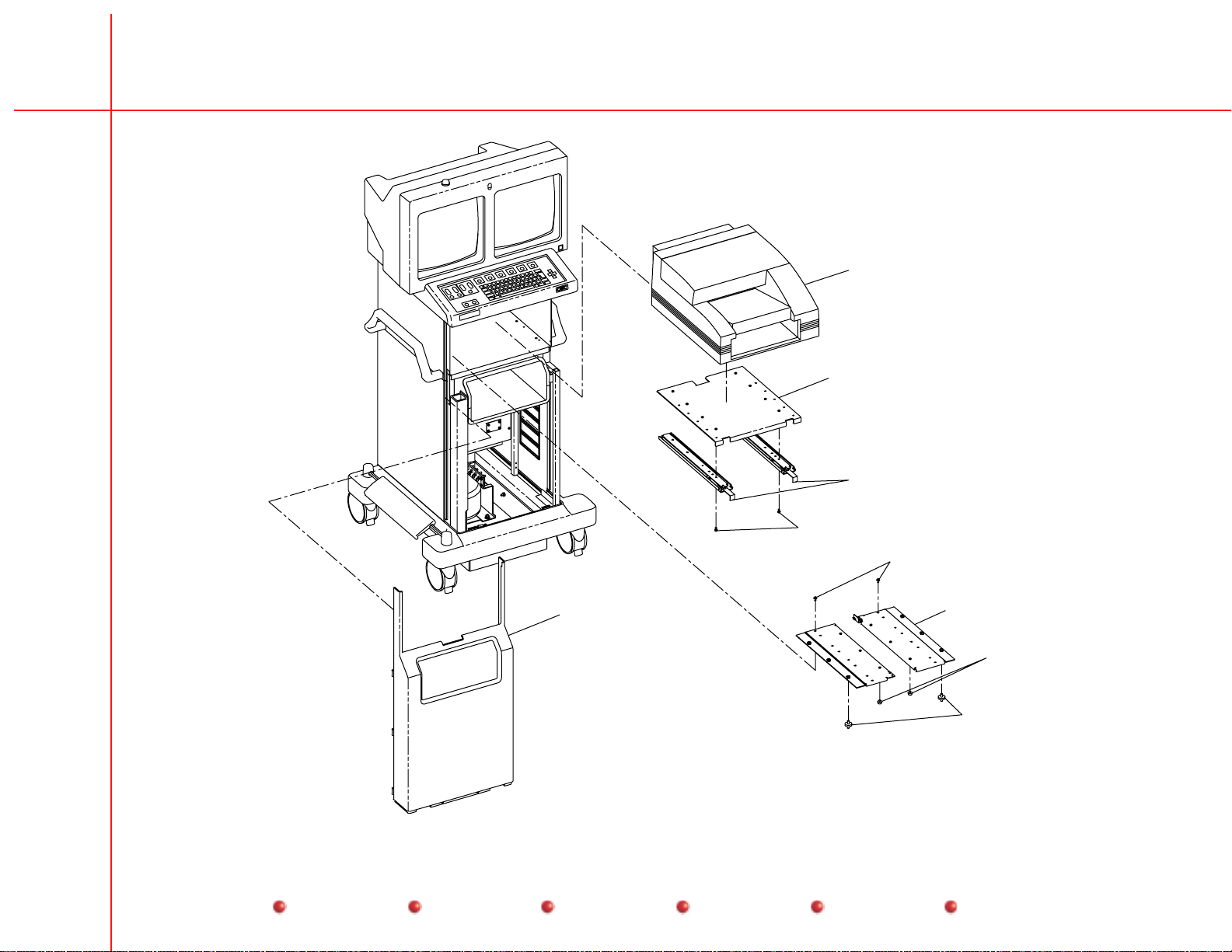
Figure 3. Front Cover with Codonics Printer Parts List .........................................................................................12
Front Cover with Codonics Printer Exploded View.................................................................................13
Figure 4. Optional Lenzar and Front Cover Parts List............................................................................ ...............14
Optional Lenzar and Front Cover Exploded View ..................................................................................15
Figure 5. Keyboard Parts List................................................................................................................................16
Keyboard Exploded View .......................................................................................................................17
Figure 6. Front and Side Parts List ............................................................................................. ..........................18
Front and Side Exploded View...............................................................................................................19
Figure 7. Rear Cover, Fan, and Power Cord Par ts List .........................................................................................20
Rear Cover, Fan, and Power Cord Exploded View.................................................................................21
Figure 8. Base Cover, Brake Pedal, and Casters Parts List..................................................................................22
Base Cover, Brake Pedal, and Casters Exploded View .........................................................................23
Figure 9. Monitor Rear Parts List..........................................................................................................................24
Monitor Rear Exploded View..................................................................................................................25
Figure 10. Electronic Rack Fans and Surge Supperssor PCB Par ts List ................................................................26
Electronic Rack Fans and Surge Supperssor PCB Exploded View .......................................................27
5OEC
Contents Installation Service Schematics Periodic Maintenance Illustrated Parts
Page 6

Workstation Illustrated Parts Manual
Figure 11. Electronic Rack Parts List ........................................................................................... ...........................28
Electronic Rack Exploded View..............................................................................................................29
Figure 12. Electronic Rack Parts List ......................................................................................................................30
Electronic Rack Exploded View..............................................................................................................31
Figure 13. Electronic Rack Parts List ......................................................................................................................32
Electronic Rack Exploded View..............................................................................................................33
Figure 14. Electronic Box 00-880413-01 Parts List.................................................................................................34
Electronic Box 00-880413-01 External View..........................................................................................35
Figure 15. Cine Dr ive, 15 FPS Parts List ................................................................................................................36
Cine Drive, 15 FPS Exploded View........................................................................................................37
Figure 16. Cine Dr ive, 30 FPS Parts List (1 of 3)....................................................................................................38
Cine Drive, 30 FPS Exploded View (1 of 3) ...........................................................................................39
Figure 17. Cine Dr ive, 30 FPS Parts List (2 of 3)....................................................................................................40
Cine Drive, 30 FPS Exploded View (2 of 3) ...........................................................................................41
Figure 18. Cine Dr ive, 30 FPS Parts List (3 of 3)....................................................................................................42
Cine Drive, 30 FPS Exploded View (3 of 3) ...........................................................................................43
6OEC
Contents Installation Service Schematics Periodic Maintenance Illustrated Parts
Page 7
Workstation Illustrated Parts Manual
7OEC
OEC Workstation
Contents Installation Service Schematics Periodic Maintenance Illustrated Parts
Page 8

Workstation Illustrated Parts Manual
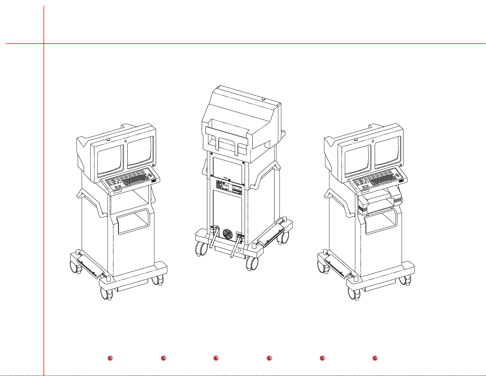
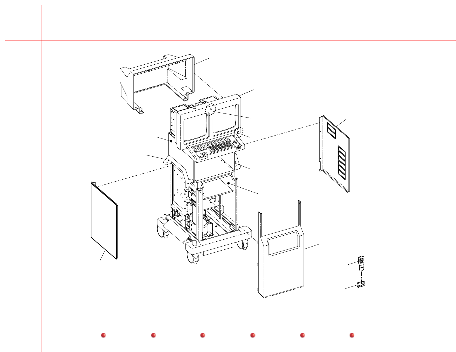
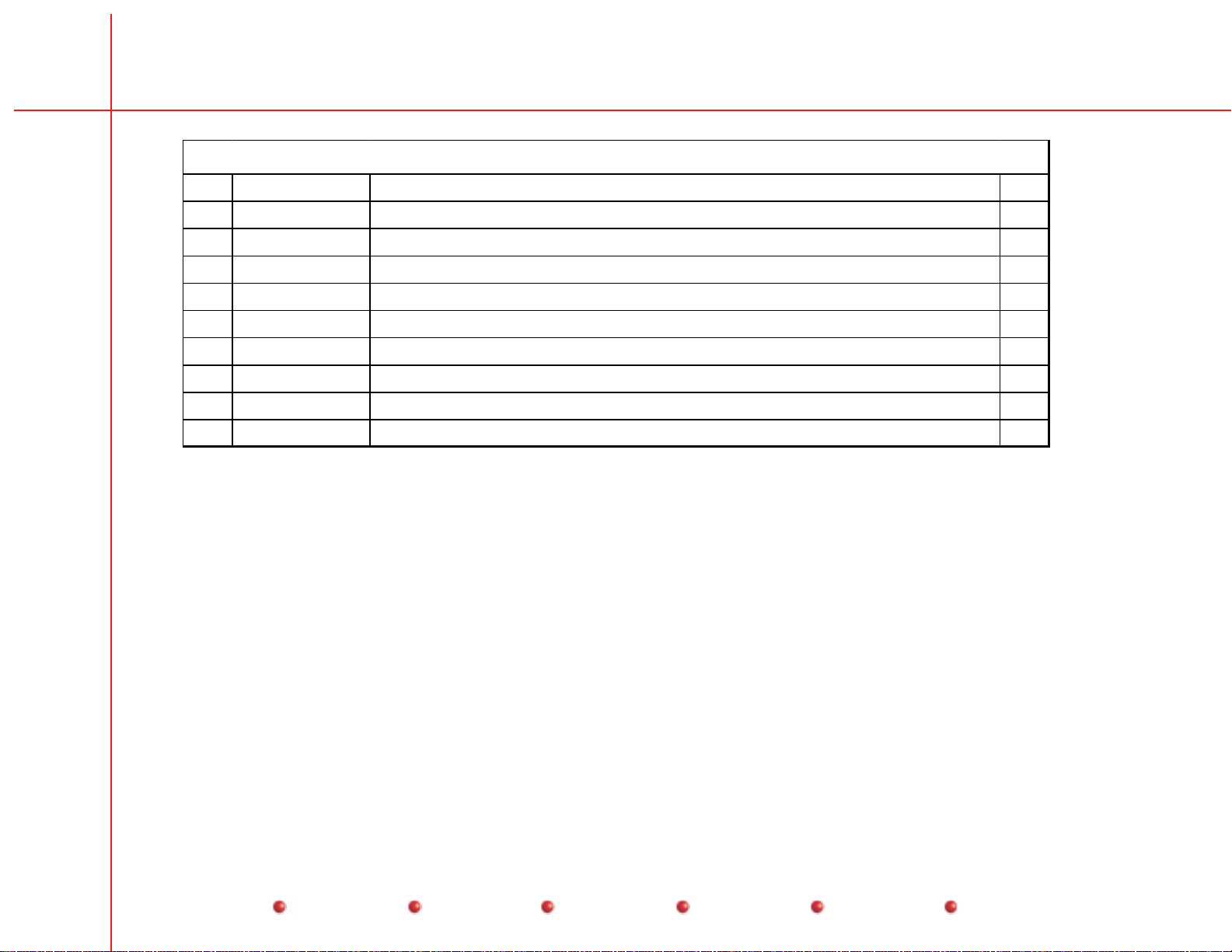
Figure 1. Front, Monitor, and Side Covers Parts List
Item Part Nu mb er Descriptio n Qty
1 00-875983 - 02 As sembly, Housing, Moni tor 1
2 00-880616 - 01 Bezel, Monitor 1
3 00-880660 - 01 Lens, Front , Col or e d 1
3 00-880660-02 Lens, Fr ont , C lear 1
4 00-879474 - 01 Assem bly, C able, On / O f f , W or kStat i on 1
5 00-875986 - 07 Cover , S ide Lower , R ight 1
6 27-590973 - 00 Filt er, S m all 2
7 27-590974 - 00 Filt er, Large 2
8 00-875981 - 04 Cove r , Side, Up per , Right 1
9 00-880829 - 01 As m , Cover , Shelf, L ower 1
10 00-880393 - 02 Cover , Front P ane l 1
11 00-901382 - 02 Asm , I . R. R em ot e, 9800 1
8OEC
12 00-879636 - 01 Hol der , H a nd C ont r o l , 9800 1
13 00-875986 - 06 Cover , S ide Lower , Le f t 1
14 00-876466 - 02 Handl e, M onitor C ar t 2
15 00-875981 - 03 Cove r , Side, Up per , Left 1
Contents Installation Service Schematics Periodic Maintenance Illustrated Parts
Page 9
Workstation Illustrated Parts Manual
9OEC
1
2
13
3
5
6
7
15
4
14
8
9
10
11
5
12
Figure 1. Front, Monitor, and Side Covers Exploded View
Contents Installation Service Schematics Periodic Maintenance Illustrated Parts
Page 10

Workstation Illustrated Parts Manual
Figure 2. Rear and Side Covers Parts List
Item P art N u m b er Descrip t i o n Qty
1 00-875986- 0 6 Cover, S ide Lower 1
2 00-879309- 0 1 Cover, R ear Panel 1
3 23-621841- 0 0 Fas t en er , 1/4 Turn, Stud, Philips, SZC 6
4 00-875986- 0 7 Cover, S ide Lower 1
10OEC
Contents Installation Service Schematics Periodic Maintenance Illustrated Parts
Page 11

Workstation Illustrated Parts Manual
4
11OEC
1
3
2
Figure 2. Rear and Side Covers Exploded View
Contents Installation Service Schematics Periodic Maintenance Illustrated Parts
Page 12
Workstation Illustrated Parts Manual
Figure 3. Front Cover with Codonics Printer Parts List
Item Part Nu mb er Descriptio n Qty
1 00-901406- 01 Inst a nt F ilm / P a per Pri nt er 1
2 00-880891- 0 1 Mount , Upper , Codoni c s 1
3 21-301871- 00 Rail, S l ide, B al l Bear i n g, C hass i s 2
4 12-225108- 0 6 Screw, SEMS, Spri ng, Pan, Torx, 8-32, 3/8, SZC 8
5 12-225108- 0 6 Screw, SEMS, Spri ng, Pan, Torx, 8-32, 3/8, SZC 16
6 00-880892- 0 1 Mount , Lower , Codoni c s 2
7 23-608980- 0 0 Bum pe r , St ud M oun t , .625D X .312 Thread, Rubber, Black 6
8 21-699937- 0 0 Mount , Shock Absorber , 60lb, C ompressi on, 15lb s heer 6
9 00-880393- 04 Cove r , F r ont Panel 1
12OEC
Contents Installation Service Schematics Periodic Maintenance Illustrated Parts
Page 13
Workstation Illustrated Parts Manual
13OEC
1
2
3
4
5
9
6
8
Figure 3. Front Cover with Codonics Printer Exploded View
Contents Installation Service Schematics Periodic Maintenance Illustrated Parts
7
Page 14

Workstation Illustrated Parts Manual
Figure 4. Optional Lenzar and Front Cover Parts List
Item Part Nu mb er Descriptio n Qty
1 00-901265- 01 Cam e ra , H ar d C op y, 2/ 1, Le nzar 1
2 00-876325- 07 B oot , Lenz ar , E nglish 1
3 00-881145- 01 K i t , Panel/ Boot, Lenzar , Engli s h 1
4 13-311106- 0 0 Nut, H exa gon-Lock-E x t e r nal-T o ol , 6-32, Steel Sta inless, NA ,A=.313 1
5 12-225104- 0 5 Sc r ew, SEMS Spr ing, Pan, Torx, 4- 4 0, 5/ 16, SZC 12
6 88-299319- 00 A dhesive, S ea l ant , Blue, B ottl e, . 7oz , . 42540 AR
7 00-880393- 0 1 Cove r , Fr ont Panel, Lenzar 1
14OEC
Contents Installation Service Schematics Periodic Maintenance Illustrated Parts
Page 15

Workstation Illustrated Parts Manual
15OEC
1
2
3
4
5
6
7
Figure 4. Optional Lenzar and Front Cover Exploded View
Contents Installation Service Schematics Periodic Maintenance Illustrated Parts
Page 16

Workstation Illustrated Parts Manual
Figure 5. Keyboard Parts List
Item Part Nu mb er Descriptio n Qty
1 00-879280- 0 1 Ass em bly, Keyboard, Text 1
1 00-879280- 0 2 Ass em bly, Keyboard, Text, Icon 1
2 00-880980- 0 1 Nam eplate, ESP 1
2 00-880980- 0 2 Nam eplate, ESP Ci ne 1
2 00-880980- 0 3 Nam eplate, Vascul ar 1
2 00-880980- 0 4 Nam eplate, Neuro/ Vas 1
2 00-880980- 0 5 Nam eplate, Cardi ac 1
3 00-880615- 0 1 Cover , K ey board, B ottom 1
4 12-215006- 06 Sc r ew s, M ac hi ne, Fl at , Torx, 6- 32, SZC 6
5 13-311106- 00 Nut , Hexagon-Loc k- Extern al - Tool, 6- 32, Steel S t a i nl e ss, N A, A = . 313 2
6 00-876767- 0 1 Ass em bly, Alarm, A udio 1
7 12-225106- 0 4 Screw, SEMS Spring, ( Crest Cup), Pan, Torx, 6- 32, 1/4, SZC 8
8 00-876613- 0 6 Cont rol Panel P rocessor 1
16OEC
Contents Installation Service Schematics Periodic Maintenance Illustrated Parts
Page 17

Workstation Illustrated Parts Manual
17OEC
1
2
3
5
6
4
7
8
Figure 5. Keyboard Exploded View
Contents Installation Service Schematics Periodic Maintenance Illustrated Parts
Page 18

Workstation Illustrated Parts Manual
Figure 6. Front and Side Parts List
Item Part Nu mb er Descriptio n Qty
1 13-321115- 0 0 Nut , Hexagon - Loc k, Fl a nged, 5/16- 18, St eel 4
2 00-900971- 0 1 Tr a nsformer, Isolati o n, 2415VA 1
3 00-880317- 01 Power C ont r ol Board 1
4 12-225106- 08 Sc r ew , SEM S , Spri ng ( C r est Cup), Pan, T o rx , 6- 32, 1/ 2 SZC 6
5 22-012002- 00 Cl a mp , C able & Wi r e H ar ne ss, 5/8D, . 50W, Nylon 2
6 12-225104- 06 Sc r ew , SEM S , Spri ng ( C r est Cup), Pan, T o rx , 4- 40, 3/ 8 SZC 2
7 00-901259- 01 Te r minal B lock (S CD) 1
8 13-311104- 00 Nut , Hexagon-Loc k- Extern al - Tool, 4- 40, Steel S t a i nl e ss, N A, A = . 250 2
9 00-879613- 01 Plate, M ount i n g, T e r mi n al 1
18OEC
Contents Installation Service Schematics Periodic Maintenance Illustrated Parts
Page 19

Workstation Illustrated Parts Manual
9
7
8
19OEC
6
1
5
4
3
Figure 6. Front and Side Exploded View
Contents Installation Service Schematics Periodic Maintenance Illustrated Parts
2
Page 20

Workstation Illustrated Parts Manual
Figure 7. Rear Cover, Fan, and Panel Cord Parts List
Item Part Nu mb er Descriptio n Qty
1 00-879322- 0 1 Ass em bly, Cable, Interc onnec tion 1
2 55700475- 00 Cir cuit B r eaker , 10A, D P ST, 12 5/ 250VAC , Panel 1
3 55-700452- 00 Ci r c ui t Breaker , 5. 0A, D P ST, 250VAC / 5 0V DC, Panel 1
4 20-839918- 00 Fa n, A x i al , 115VAC, 109 C FM, 31 00R PM 1
5 13-311106- 00 Nut , Hexagon-Loc k- Extern al - Tool, 6- 32, Steel S t a i nl e ss, N A, A = . 313 4
6 12-215006- 08 Sc r ew , SEM S , Spri ng ( C r est Cup), Pan, T o rx , 6- 32, 1/ 2 SZC 8
7 12-225106- 12 Sc r ew , SEM S , Spri ng ( C r est Cup), Pan, T o rx , 6- 32, 3/ 4 SZC 4
8 20-839926- 0 0 Guar d, Fan 1
9 00-900686- 01 Power C or d 1
10 00-880594- 01 As sem bl y , P ower C ord , 100- 127V 1
11 00-879309- 01 Cove r , R ear P a nel 1
12 23-621841- 00 Fa st ener , 1/4 Tur n, Stud, P hi lips, SZC 6
20OEC
Contents Installation Service Schematics Periodic Maintenance Illustrated Parts
Page 21

Workstation Illustrated Parts Manual
12
21OEC
11
10
6
9
6
8
7
5
4
Figure 7. Rear Cover, Fan, and Power Cord Exploded View
1
2
3
Contents Installation Service Schematics Periodic Maintenance Illustrated Parts
Page 22

Workstation Illustrated Parts Manual
Figure 8. Base Cover, Brake Pedal, and Casters Parts List
Item Part Nu mb er Descriptio n Qty
1 00-879615- 01 Cove r , B as e 1
2 00-879149- 02 Peda l , Brake, Lef t 1
3 12-709008-00 Spring 2
4 00-876624- 01 Bar , Brake 2
5 14-111114- 00 Washer , P lain, 1/ 4, Ste el S tainl es s, N A, ID=.26 5, O D = . 500 6
6 14-211114- 0 0 Washer, Lock, Heli cal Spr ing, 1/ 4, St e el St ainless, MS 35338- 6
7 12-311114- 12 Sc r ew , N A, S oc ket , H ex agon, 1/ 4- 20 , 3/ 4, SZC , 8 6
8 00-900696- 0 1 Caster, Lo ck ing, 5-Inch 2
9 00-877298- 01 Pus her , C able, 5- I nch C as t er 4
10 00-900695- 0 1 Caster, Swi v el, 5-Inch 2
22OEC
Contents Installation Service Schematics Periodic Maintenance Illustrated Parts
Page 23

Workstation Illustrated Parts Manual
23OEC
1
2
3
4
5
3
6
7
10
8
9
Figure 8. Base Cover, Brake Pedal, and Casters Exploded View
Contents Installation Service Schematics Periodic Maintenance Illustrated Parts
Page 24

Workstation Illustrated Parts Manual
Figure 9. Monitor Rear Parts List
Item Part Nu mb er Descriptio n Qty
1 00-875983- 0 2 As sembly, Housing, Moni tor 1
2 00-874222- 0 4 As sembly, IR R ec eiver PCB 1
3 00-879635- 01 Hou si ng , D et ec t or , I R Receiver 1
4 12-225106- 08 S cr ew , SEM S, S pr i ng ( C r es t C up) , Pan, T or x , 6- 32, 1/ 2 SZC 8
5 00-900751- 0 0 Lamp, X-R ay On, (SCD) 1
6 13-311106- 0 0 Nut, H exa gon-Lock-E x t e r nal-T o ol , 6-32, Steel St ainless, NA , A= . 3 13 8
7 20-839956- 0 0 Fa n, Axial, 1 15VAC, 75C FM, 2200RPM 2
8 12-225104- 08 S cr ew , SEM S, S pr i ng ( C r es t C up) , Pan, T or x , 4- 40, 1/ 2 SZC 2
9 00-901309- 01 T er m i nal Bl oc k, 9- B lock 1
10 12-225108- 06 S cr ew , SEM S, S pr i ng ( C r es t C up) , Pan, T or x , 8- 32, 3/ 8 SZC 8
11 00-901076- 04 Gene ric, M oni tor, 16 H igh Resoluti on, Lef t 1
12 00-901380- 02 T ouch Screen ( SCD ) 1
13 00-901076- 01 Gene ric, M oni tor, 16 H igh Resoluti on, R ight 1
24OEC
Contents Installation Service Schematics Periodic Maintenance Illustrated Parts
Page 25

Workstation Illustrated Parts Manual
25OEC
1
13
10
10
12
10
10
11
6
2
3
4
4
5
7
6
9
8
7
Figure 9. Monitor Rear Exploded View
Contents Installation Service Schematics Periodic Maintenance Illustrated Parts
Page 26

Workstation Illustrated Parts Manual
Figure 10. Electronic Rack Fans, and Surge Suppressor PCB Parts List
Item Part Nu mb er Descriptio n Qty
1 12-215006- 10 S cr ew , M ac hi ne, Fl at , Torx, 6- 32, 5/8 SZ C 8
2 20-839918- 0 0 Fa n, Axial, 1 15VAC, 109C FM, 3100RPM 2
3 13-311106- 0 0 Nut, H exa gon-Lock-E x t e r nal-T o ol , 6-32, Steel St ainless, NA , A= . 3 13 8
4 12-225106- 10 S cr ew , SEM S, S pr i ng ( C r es t C up) , Pan, T or x , 6- 32, 5/ 8 SZC 8
5 00-880540- 01 A ssem bly, P CB, S ur ge Suppress or 1
6 12-225106- 08 S cr ew , SEM S, S pr i ng ( C r es t C up) , Pan, T or x , 6- 32, 1/ 2 SZC 6
26OEC
Contents Installation Service Schematics Periodic Maintenance Illustrated Parts
Page 27

Workstation Illustrated Parts Manual
27OEC
5
1
2
6
1
3
4
2
3
3
4
Figure 10. Electronic Rack Fans and Surge Suppressor PCB Exploded View
Contents Installation Service Schematics Periodic Maintenance Illustrated Parts
Page 28

Workstation Illustrated Parts Manual
Figure 11. Electronic Rack Parts List
Item Part Nu mb er Descriptio n Qty
1 00-879425-01 Cable, Assembly, Power Supply - DC Distribution 1
2 00-879426- 0 1 Cable, A s sembly, Twin BN C Bulkhead 1
3 00-879427-01 Cable Assembly, DC Distribution - Hard Disk Drive 1/2 1
4 00-879428- 01 Cable Asse mb l y, EMI Box - C P P 1
5 00-879429- 02 Cable Asse mb l y, DC D i st r ibuti on - D aughter B oar ds 1
6 00-879430-01 Cable Assembly, DC Distribution - Drives 1
7 00-879431-01 Cable Assembly, DC Distribution - CPU 1
8 00-879432-01 Cable Assembly, DC Distribution - System Interface 1
9 00-880390- 01 Cable Asse mb l y, Displ ay C ont r ol - Lenzar 1
10 00-879460- 01 Cable Asse mb l y, I m age Process or - Video C ont r o l 1
11 00-879461- 01 Cable Asse mb l y, I m age Process o - Displ ay C ont r ol 1
12 00-880536- 01 Cable Asse mb l y, Displ ay C ont r ol - VC R, R S 1 70 1
28OEC
13 00-879463- 0 1 Cable, A s sembly, Video Control - System I n t erface 1
14 00-879468- 01 Cable Asse mb l y, Fast S c an - B N C Ri ght 1
15 00-879473- 01 Cable Asse mb l y, System I nt er c onnect - EM I Box 1
16 00-880786- 01 Cable Asse mb l y, Safet y G r ound Str ap 1
17 00-880786- 01 Cable Asse mb l y, Safet y G r ound Str ap 1
18 00-880434- 01 Cable Asse mb l y, TB3 - P S1 1
19 00-880435- 01 Cable Asse mb l y, TB2 - F L 1 1
20 00-879468- 02 Cable Asse mb l y, Fast S c an - B N C Left 1
21 00-879476- 01 Cable Asse mb l y, System I nt er c onnect - VC R/M odem 1
22 00-879429- 01 Cable Asse mb l y, DC D i st r ibuti on - D aughter B oar ds 1
23 00-880537- 01 Cable Asse mb l y, Video C ont r o l - V C R, RS170 1
24 00-880609- 01 Label, Groun di ng, Elect r onic Rack 4
25 51-500507- 00 Har dware K i t , Connector , Jac k S o cket, 4-40, . 50L 1
Contents Installation Service Schematics Periodic Maintenance Illustrated Parts
Page 29

Workstation Illustrated Parts Manual
See Figure 14
29OEC
See Figure 12
See Figure 13
Figure 11. Electronic Rack Exploded View
Contents Installation Service Schematics Periodic Maintenance Illustrated Parts
Page 30

Workstation Illustrated Parts Manual
Figure 12. Electronic Rack Parts List
Item Part Nu mb er Descriptio n Qty
1 12-225106- 0 6 Screw, SEMS, Spri ng ( Crest Cup), Pan, Torx, 6- 32, 3/8, SZC 27
2 22-012004- 00 Cl a mp , C able & Wi r e, I D, .5 0W, Nylon 1
3 00-901400- 01 Power S upply, +5, +/- 12, W or kstati on 1
4 12-225106- 0 4 Screw, SEMS, Spri ng ( Crest Cup), Pan, Torx, 6- 32, 1/4, SZC 19
5 22-012002- 00 Cl a mp , C able & Wi r e/ I D, 5/ 8D , . 50 W, N ylon 1
6 00-879119-01 PCB Assembly, DC Distribution 1
7 13-311106- 00 Nut , Hexagon-Loc k- Extern al - Tool, 6- 32, Steel S t a i nl e ss, N A, A = . 313 8
8 22-012102- 0 0 Cl a m p, Cable & Wire, .437X, 75BQ, .219W, N y lon 6
9 21-699935- 00 Mount , Shock, ABS , 15L b C om pr ess i on, 2L b S heer , Nati onal Rubber 4
10 88-299284- 00 Adhe si v e, S ealant, P u r pl e, B ottl e, 10CC, Loc t i t e , 222- 21 AR
11 00-880435- 01 Cable Asse mb l y, TB2 - F L 1 1
12 00-901308- 01 Te r minal B lock, 2 B lock 1
13 12-225104- 0 8 Screw, SEMS, Spri ng ( Crest Cup), Pan, Torx, 4- 40, 1/2, SZC 2
30OEC
Contents Installation Service Schematics Periodic Maintenance Illustrated Parts
Page 31

Workstation Illustrated Parts Manual
31OEC
1
2
9
10
1
3
4
7
5
6
8
1
Figure 12. Electronic Rack Exploded View
Contents Installation Service Schematics Periodic Maintenance Illustrated Parts
Page 32

Workstation Illustrated Parts Manual
Figure 13. Electronic Rack Parts List
Item Part Nu mb er Descriptio n Qty
1 12-225106- 0 4 Screw, SEMS, Spri ng ( Crest Cup), Pan, Torx, 6- 32, 1/4, SZC 19
2 00-880413- 0 1 Ass em bly, Elect rical Box 1
3 00-879880- 0 1 Mount , Vi bratio n, Cine D isk, 1
4 13-311108- 00 Nut , Hexagon-Loc k- Extern al - Tool, 8- 32, Steel S t a i nl e ss, N A, A = . 344 4
5 12-225106- 06 Sc r ew , SEN S, S pr i ng ( C r es t C up) , Pan, T or x , 6- 32, 3/ 8, SZC 27
6 00-879882- 0 1 Mount , Di sk 1
7 00-880416-01 Assembly, Disk, Hard Drive, Formatted 1
8 00-881092- 0 1 Ass em bly, M otherboard , Workstation 1
9 00-879018- 0 1 Ass em bly, PCB , Imag e Processor 1
10 00-878957- 0 1 Ass em bly, PCB , Hi gh - Resolut ion Display Contr ol 1
11 00-879056- 0 2 Ass em bly, PCB , System Interfa ce 1
12 00-901436- 0 1 Cont roll er, P CA, VGA , IS A 1
13 00-879004- 01 As sem bl y , P CB, V i d eo C ont r ol 1
32OEC
Contents Installation Service Schematics Periodic Maintenance Illustrated Parts
Page 33

Workstation Illustrated Parts Manual
8
33OEC
1
2
See Figure 14
5
13
5
6
12
1
5
7
3
11
5
10
9
4
Figure 13. Electronic Rack Exploded View
Contents Installation Service Schematics Periodic Maintenance Illustrated Parts
Page 34

Workstation Illustrated Parts Manual
Figure 14. Electronic Box 00-880413-01Parts List
Item Part Nu mb er Descriptio n Qty
1 67-700002- 00 Met er , Elect r ical, AC, H R / Tnts, 6- Digi t 1
2 51-950001- 00 Con nect or , Coupl er , Feedthr ough, Ri ght A ngle, 6- P os i t ion, Mod. Black 1
3 00-879186- 0 1 PCB Assembl y , Ext e r nal, I nterfac e 1
4 00-901421- 0 1 Dr ive, Archi va l, 2G Byte 1
5 00-900669- 0 1 Dr ive, Floppy Disk, 1.5", 1.44MB yte 1
6 12-225106- 04 S cr ew , Sems, Spring , P an, Trx, 6- 32, 1/ 4, SZ C 9
7 51-500507- 00 Har d w ar e K it, C onne ct or , Jack S oc ket Set, 4- 40, . 50L 5
8 88-299319- 00 A dhesive, S ea l ant , Blue, B ottl e, . 7oz , 42540 1
9 00-880646-01 Cable Assembly, Host CPU, Parallel 1
10 00-880647- 0 1 Cable Ass embly, Host C PU, Seri a l 1
11 22-429900- 00 S t andof f, H ex, F, 4-40, .250L, B CD 2
12 00-901596- 01 Cab l e, VGA E x t ension (S C D) 1
34OEC
13 00-881071- 0 1 Cable Ass embly, key board Extension 1
14 00-879612- 0 2 Overlay, Exter nal Int erface 1
15 00-880536- 03 Cab l e A s sem bly, D i sp l ay Contr ol - V C R, R S 170 1
16 00-880534- 01 Cab l e A s sem bly, D i sp l ay Contr ol - E xt er n al M oni tor, Le f t , F as t S c an 1
17 00-880515- 01 Cab l e A s sem bly, D i sp l ay Contr ol - E xt er n al M oni tor, Right , Fast S c an 1
Contents Installation Service Schematics Periodic Maintenance Illustrated Parts
Page 35

Workstation Illustrated Parts Manual
16
15
14
7
13
35OEC
1
2
17
3
11
12
8
4
7
7
8
9
5
7
8
10
6
Figure 14. Electronic Box 00-880413-01 External View
Contents Installation Service Schematics Periodic Maintenance Illustrated Parts
Page 36

Workstation Illustrated Parts Manual
Figure 15. Cine Drive, 15 FPS Parts List
Item Part Nu mb er Descriptio n Qty
1 12-225106- 0 4 Screw, SEMS, Spri ng ( Crest Cup), Pan, Torx, 6- 32, 1/4, SZC 9
2 00-880413- 0 1 Ass em bly, Elect rical Box 1
3 12-225106- 06 Sc r ew , SEM S , Spri ng , P an, Tor x, 6- 32, 3/ 8 , S ZC 14
4 00-880923-01 Asssembl y, P C B , C i ne Br i dge, 9800 1
5 12-225104- 04 Sc r ew , SEM S , Spri ng , P an, Tor x, 4- 40, 1/ 4 , S ZC 2
6 00-879225- 01 Br ac ket , PCB , 9800 1
7 00-879501- 0 1 Ass em bly, PCB , Ci ne 2- Disk, B’ Plane, 9800 1
8 00-901455- 0 1 Har d Dri ve, FC-AL CHE 9LP, 9.1 GB 2
9 00-879882- 0 1 Mount , Di sk , 9800 3
10 12-225106- 04 Sc r ew , SEM S , Spri ng , P an, Tor x, 6- 32, 1/ 4 , S ZC 11
11 00-880416- 0 1 Ass em bly, Disk, Hard D rive, Form atted 1
12 00-879462- 01 Cable Asse mb l y, I P-C i ne Bridg e, 9800 ( N ot Shown) 1
36OEC
13 00-879464- 01 Cable Asse mb l y, 4/30 FP S-C i ne B’P l ( N ot Show n) 1
14 00-879427-02 Cable Assembly, DC Dist-HDD, 9800 (Not Shown) 1
15 00-880721- 01 Cable Asse mb l y, I fiber Channel D ( N ot Show n) 1
16 00-879427-01 Cable Assembly, DC Dist-HDD 1/2, 9800 (Not Shown) 1
Contents Installation Service Schematics Periodic Maintenance Illustrated Parts
Page 37

Workstation Illustrated Parts Manual
37OEC
Items 1 and 2 are shown
again in this figure for
clarity and reference.
1
2
See Figure 14
3
6
3
5
7
4
3
10
3
10
3
8
9
8
9
10
11
9
Figure 15. Cine Drive, 15 FPS Exploded View
Contents Installation Service Schematics Periodic Maintenance Illustrated Parts
Page 38

Workstation Illustrated Parts Manual
Figure 16. Cine Drive, 30 FPS Parts List (1 of 3)
Item Part Nu mb er Descriptio n Qty
1 00-880788-01 Chasssis, C i ne E nclosur e 1
2 12-225106- 04 S cr ew , SEM S, S pr i ng ( C r es t C up) , Pan, T or x , 6- 32, 1/ 4, SZC 14
3 00-880413- 0 1 As sembly, Electric al Box 1
4 12-215006- 0 8 Sc r ew, M ach, Flat, Torx, 6- 3 2, 1/2, SZC 3
5 00-879609- 0 1 Fitt ings, Bulkhead, 9800 1
6 12-225106- 06 S cr ew , Sems, Spring , P an, Torx, 6- 32, 3/ 8, SZC 11
7 00-879225- 01 B r acket, P C B, 9800 1
8 12-225104- 04 S cr ew , Sems S pr ing, P an, Torx, 4- 40, 1/ 4, SZC 2
9 00-880923- 0 1 As sembly, PCB, C ine Br idge, 9800 1
10 00-879882- 0 1 Mount , Disk 1
11 00-880416- 0 1 As sembly, Disk, Har d Driv e, Forma t ted 1
38OEC
Contents Installation Service Schematics Periodic Maintenance Illustrated Parts
Page 39

Workstation Illustrated Parts Manual
2
39OEC
1
See Figure 17
Items 2 and 3 are shown
again in this figure for
clarity and reference.
Contents Installation Service Schematics Periodic Maintenance Illustrated Parts
3
See Figure 14
5
4
6
7
8
9
Figure 16. Cine Drive, 30 FPS Exploded View (1 of 3)
11
2
2
10
Page 40

Workstation Illustrated Parts Manual
Figure 17. Cine Drive, 30 FPS Parts List (2 of 3)
Item Part Nu mb er Descriptio n Qty
1 12-225108- 06 S cr ew , Sems, Spring , P an Torx, 8- 32, 3/ 8, SZC 26
2 00-879609- 0 1 Fitt ings, Bulkhead, 9800 2
3 12-215006- 0 8 Sc r ew, M ach, Flat, Torx, 6- 3 2, 1/2, SZC 6
4 00-880788- 01 Cha ssis, C i ne E ncl o sur e 1
5 00-879611- 01 S pacer , Bulkhea d, 9800 1
6 20-359981- 0 0 Bus hing, Soulder, Nylon, I D= .19 0 2
7 12-999975- 0 0 Sc r ew, N a, Shoulder, Sli t , 8-32, 3/16 x 1/4, SST 2
8 00-881067- 01 S pacer , I s ol at o r , 9800 2
9 21-699936- 0 0 Mount , Sh Abs, 20 Lb Cprsn 4 Lb Shr, Nprn 4
10 00-880794- 01 B r acket, S hock Mo unt , Bottom 1
11 12-225108- 12 S cr ew , Sems, Spring , P an Torx, 8- 32, 3/ 4, SZC 2
12 12-215008- 0 6 Sc r ew, M ach, Flat, Torx, 8- 3 2, 3/8, SZC 2
40OEC
13 00-880920- 01 B r acket, P i vo t 1
14 00-880789- 01 Cov er , C ine Enclosure 1
15 12-225108- 06 S cr ew , Sems, Spring , P an, Torx, 8- 32, 3/ 8, SZC 26
16 00-901400- 01 P ow er Supply, + 5, + / - 12 , Wor kstati on, 980 0 1
17 00-881065- 0 1 Bracket, Fuse Holder, 9800 1
18 12-225106- 04 S cr ew , Sems, Spring , P an, Torx, 6- 32, 1/ 4, SZC 23
19 12-225108- 04 S cr ew , Sems, Spring , P an, Torx, 8- 32, 1/ 4, SZC 4
20 00-881064- 01 B r acket, P ow er Supply, 9800 1
21 22-429714- 0 0 Standoff , Round, F/ F, 6- 32, 4.14L, AL 1
22 00-881064- 02 B r acket, P ow er Supply, 9800 1
23 00-880797- 01 B r acket, Moun t i ng, Cine E nclosure 2
24 13-311108- 00 Nut, H ex- LK-E X T-T , 8-32, SST, NA, A = . 344 4
Contents Installation Service Schematics Periodic Maintenance Illustrated Parts
Page 41

Workstation Illustrated Parts Manual
41OEC
15
16
17
19
18
20
21
22
13
12
11
18
15
24
23
15
24
See Figure 18
6
7
23
1
2
3
4
3
2
5
14
10
9
8
Figure 17. Cine Drive, 30 FPS Exploded View (2 of 3)
Contents Installation Service Schematics Periodic Maintenance Illustrated Parts
Page 42

Workstation Illustrated Parts Manual
Figure 18. Cine Drive, 30 FPS Parts List (3 of 3)
Item Part Nu mb er Descriptio n Qty
1 00-870793- 01 B r acket, S hock Mo unt , Top 1
2 21-699936- 00 Mount , SH A BS, 20Lb Cprsn 4 Lb S hr , Nprn 4
3 12-225108- 06 S cr ew , Sems, Spring , P an, Torx, 8- 32, 3/ 8, SZC 26
4 00-881066-01 Guard, Connector, 9800 2
5 12-225106- 04 S cr ew , Sems, Spring , P an, Torx, 6- 32, 1/ 4, SZC 23
6 12-225106- 06 S cr ew , Sems, Spring , P an, Torx, 6- 32, 3/ 8, SZC 11
7 00-879410-01 Assembly, PCB, Cine 4 Disk, B’ P lane, 9800 1
8 00-901455- 0 1 Har d Driv e, FC -AL C HE 9LP, 9. 1 G B 4
9 00-880796- 0 1 Plate, Air Dam 1
10 12-225104- 06 S cr ew , Sems, Spring , P an, Torx, 4- 40, 3/ 8, SZC 2
11 00-901314- 01 T er m i nal Bl oc k, 3 B lock, 9800 1
12 12-225106- 02 S cr ew , Sems, Spring , P an, Torx, 6- 32, 1- 1/ 4 , S ZC 8
42OEC
13 20-839956- 00 F an, Axil , 11 5 V ac, 75 CF M , 2200 RPM 2
14 00-880792- 01 B r acket, F an 1
15 00-880790- 01 B r acket, Moun t i ng, Cine, I nside 1
Contents Installation Service Schematics Periodic Maintenance Illustrated Parts
Page 43

Workstation Illustrated Parts Manual
43OEC
1
2
12
10
15
3
3
13
5
4
3
14
6
3
11
4
7
3
3
8
9
3
5
6
Figure 18. Cine Drive, 30 FPS Exploded View (3 of 3)
Contents Installation Service Schematics Periodic Maintenance Illustrated Parts
 Loading...