

Page 1

5483603-8EN-20
Rev 1
© 2025-07
OEC Medical Systems, Inc
All rights reserved.
OEC® Elite
User Manual
Page 2
Revision history
Revision history
Document # Revision # Release Date
5483603-8EN-20 1 2025-07
Caution U.S. federal law restricts this device to sale by or on the order of a physician,
veterinarian, or other designated licensed practitioner as appropriate for its clinical
use.
IMPORTANT: SAVE THESE INSTRUCTIONS. PLEASE READ THIS MANUAL BEFORE USING EQUIPMENT.
This manual may not be reproduced, in whole or in part, without the written permission of GE HealthCare.
OEC is a registered trademark of OEC Medical Systems, Inc. Other product and company names mentioned
herein are the property of their respective owners.
The contents of this document are accurate at the time of publication. However, changes in design and
additional features can, at any time, be incorporated in the hardware and software and may not be
reflected in this version of the document. Third party information and URLs may likewise change at any
time. Contact GE HealthCare Technical Support for clarification, if discrepancies arise.
Images in this manual, including screen shots, hardware images, diagrams, icons, and labels, can vary from
actual system appearance.
All product documentation was originally drafted, approved, and supplied by the manufacturer in English.
SLES Appliance License. The Branded Product might include components of the SUSE Linux Enterprise
Server product (SLES). Licensee acknowledges and agrees to the following restriction with respect to use of
SLES notwithstanding the license grant in the SLES end user license agreement that might accompany or
otherwise apply to the copy of SLES Licensee received with the Licensed Software: Licensee agrees to use
SLES solely for the purpose of running the Branded Product and not as a general purpose operating system.
If Licensee did not receive a copy of the SLES end user license agreement, it can be found at
http://www.suse.com/licensing/eula/
GE OEC Medical Systems, Inc., going to market as GE HealthCare. GE is a trademark of General Electric
Company used under trademark license.
OEC Medical Systems, Inc
384 Wright Brothers Drive
Salt Lake City, Utah 84116 U.S.A.
801-328-9300
GE Medical Systems SCS
283 rue de la Minière
78530 Buc, France
Telephone: (+33) 1 30 70 40 40
Fax: (+33) 1 30 70 44 40
ii
Page 3

Table of contents
Table of contents
Table of contents iii
1 Safety overview 1-1
1.1 Applicability 1-1
1.2 Product description and summary of use 1-1
1.2.1 Device description
1-1
1.2.1.1 OEC Elite description
1-1
1.2.1.2 OEC Elite ECO / SCO description
1-2
1.2.2 Intended use
1-2
1.2.3 Indications for use
1-2
1.2.4 Contraindications for use
1-2
1.2.5 Patient population
1-2
1.2.6 Use environment
1-2
1.2.7 Intended users
1-2
1.2.8 Intended clinical benefits
1-2
1.2.9 Potential side effects
1-3
1.3 Owner responsibilities 1-3
1.3.1 System compatibility
1-3
1.3.2 Operator qualifications
1-3
1.3.3 Continued compliance
1-3
1.3.4 Unauthorized modifications
1-4
1.4 OEC responsibilities 1-4
1.4.1 Essential performance
1-4
1.4.2 X-ray equipment certification
1-5
1.4.3 After-sale operating and safety practices
1-5
1.5 Electronic user manuals 1-5
1.5.1 Accessing the eIFU user manuals
1-5
1.5.1.1 Access the eIFUs on the system
1-5
1.5.1.2 Access the eIFUs on a PC
1-6
1.5.1.3 Use the eIFU PDF
1-6
1.5.2 Replacement USB device
1-6
1.5.3 Online eIFU
1-6
1.5.4 Paper copies
1-7
1.6 General safety 1-7
iii
Page 4

Table of contents
1.6.1 Contact information
1-7
1.6.2 Reporting serious incidents
1-7
1.6.3 Safety hazard alerts
1-8
1.6.4 External devices
1-8
1.6.4.1 Connection to a network
1-8
1.6.5 Wireless compliance and safety
1-9
1.6.6 Viewing the RED Declaration of Conformity
1-9
1.6.7 Patient environment
1-10
1.6.7.1 United States
1-10
1.6.7.2 International
1-11
1.7 Electrical safety 1-11
1.7.1 Electrical shock
1-11
1.7.2 Electrical fire
1-12
1.7.3 Explosion
1-12
1.7.4 Ground fault
1-12
1.7.5 Equipment malfunction
1-13
1.8 Mechanical safety 1-13
1.8.1 Improperly attached equipment
1-13
1.8.2 Equipment stability, transport, and positioning
1-13
1.8.3 Motorized and manual mechanical movement
1-14
1.8.4 Repetitive motion
1-14
1.8.5 Ingress of fluids
1-14
1.8.6 Draping
1-15
1.8.6.1 Draping the X-ray tube cooling kit
1-15
1.8.7 Cooling efficiency
1-15
1.8.8 Contact Burns
1-15
1.9 Radiation safety 1-16
1.9.1 Designated use areas
1-16
1.9.2 Personal radiation protection
1-16
1.9.3 Patient radiation protection
1-16
1.9.4 Radiation indicators
1-16
1.9.5 Radiation burns
1-16
1.9.6 Source-to-skin distance
1-17
1.9.7 Patient supports
1-17
iv
Page 5

Table of contents
1.9.8 Radiation fast stops
1-17
1.9.9 Imaging pediatric or smaller patients
1-17
1.9.10 Deterministic effects of ionizing radiation on humans
1-19
1.10 Electromagnetic compatibility 1-20
1.10.1 Performance criteria
1-20
1.10.1.1 Degraded electromagnetic compatibility
1-21
1.10.1.2 System use in the vicinity of other equipment
1-21
1.11 Patient privacy and data security 1-21
2 System setup 2-1
2.1 System Overview 2-1
2.1.1 Moving the main system components
2-1
2.1.1.1 Move the Workstation
2-1
2.1.1.2 Move the C-Arm
2-3
2.1.2 System monitors
2-6
2.1.2.1 OEC Elite Workstation monitor
2-6
2.1.2.2 OEC Elite ECO / SCO monitor
2-7
2.1.3 Workstation overview
2-8
2.1.3.1 Brake pedal
2-10
2.1.4 External connections
2-10
2.1.4.1 Connect a device to an external connector
2-12
2.1.4.2 Room Interface connector
2-12
2.1.5 Connect and view external video
2-13
2.2 First time software setup 2-14
2.2.1 Setup screens overview
2-14
2.2.1.1 System setup screens
2-15
2.2.1.2 Set up image acquisition
2-17
2.2.1.3 Set up default profile
2-19
2.2.1.4 Set up patient information
2-20
2.2.1.5 Set up position defaults
2-22
2.2.1.6 Set up touchpad and audio
2-22
2.2.1.7 DICOM network setup
2-24
2.2.1.8 Set up network configuration
2-41
2.2.1.9 Set up regional settings
2-51
2.2.1.10 Set up security
2-53
v
Page 6

Table of contents
2.2.1.11 Set up Utilities
2-80
2.2.1.12 Service screen
2-96
2.3 System startup, shutdown, and restart 2-97
2.3.1 System pairing
2-97
2.3.2 Turn on the system
2-98
2.3.2.1 If the system fails to start normally
2-98
2.3.2.2 Normal system startup procedure
2-100
2.3.2.3 Password and log in
2-104
2.3.3 Turn off the system
2-108
2.3.4 Log out
2-109
2.3.5 Immediate system shutdown
2-110
2.3.5.1 Immediate system shutdown procedure for OEC Elite
2-110
2.3.5.2 Immediate system shutdown procedure for OEC Elite ECO / SCO
2-110
2.3.6 Restart the system
2-111
2.3.7 Power loss and system restart
2-111
2.3.8 Unplug / plug the system with power on
2-112
2.3.9 Disconnect / connect the C-Arm
2-112
2.3.10 System lockups
2-112
2.3.11 Screen saver
2-113
3 System operation 3-1
3.1 C-Arm overview 3-1
3.1.1 C-Arm identification
3-1
3.1.2 C-Arm components
3-4
3.1.2.1 Super C-Arm components
3-4
3.1.2.2 Standard C-Arm components
3-5
3.1.2.3 Ergo C-Arm components
3-6
3.1.2.4 ECO C-Arm components
3-7
3.1.2.5 SCO C-Arm components
3-9
3.1.2.6 Motorized C-Arm components
3-9
3.1.3 Detector type
3-10
3.1.4 Equivalent filtration
3-10
3.1.5 Skin spacer
3-11
3.1.5.1 Attach the skin spacer
3-11
3.1.5.2 Remove the skin spacer
3-11
vi
Page 7

Table of contents
3.1.6 Anti-scatter grid
3-13
3.1.6.1 Anti-scatter grid on the flat panel system
3-13
3.1.6.2 Anti-scatter grid on the image intensifier system
3-15
3.1.7 Laser Aimer
3-16
3.1.7.1 Laser Aimer aperture locations
3-16
3.1.7.2 Turn the Laser Aimer on / off
3-17
3.1.7.3 Operate the Laser Aimer
3-18
3.1.8 Orient the C-Arm and RUI
3-18
3.1.8.1 Orient using the classic RUI
3-18
3.1.8.2 Orient using the simplified RUI
3-21
3.2 Position the C-Arm 3-23
3.2.1 Position the Standard C-Arm
3-23
3.2.1.1 Standard C-Arm lateral rotation and brake
3-23
3.2.1.2 Standard C-Arm cephalad / caudal tilt and brake
3-25
3.2.1.3 Standard C-Arm vertical column operation
3-26
3.2.1.4 Standard C-Arm horizontal cross-arm motion and brake
3-27
3.2.1.5 Standard C-Arm wig-wag motion and brake
3-29
3.2.1.6 Standard C-Arm SmartView rotation
3-30
3.2.2 Position the Super C-Arm
3-33
3.2.2.1 Super C-Arm lateral rotation and brake
3-33
3.2.2.2 Super C-Arm cephalad / caudal tilt and brake
3-35
3.2.2.3 Super C-Arm vertical column operation
3-37
3.2.2.4 Super C-Arm horizontal cross-arm motion and brake
3-38
3.2.2.5 Super C-Arm wig-wag motion and brake
3-39
3.2.3 Position the Ergo C-Arm
3-41
3.2.3.1 Ergo C-Arm lateral rotation and brake
3-41
3.2.3.2 Ergo C-Arm cephalad / caudal tilt and brake
3-45
3.2.3.3 Ergo C-Arm vertical column operation
3-47
3.2.3.4 Ergo C-Arm horizontal cross-arm motion and brake
3-48
3.2.3.5 Ergo C-Arm Wig-wag motion and brake
3-50
3.2.3.6 Ergo C-Arm SmartView rotation
3-51
3.2.4 Position the OEC Elite ECO and OEC Elite SCO C-Arm
3-54
3.2.4.1 ECO / SCO C-Arm lateral rotation and brake
3-55
vii
Page 8

Table of contents
3.2.4.2 ECO / SCO C-Arm cephalad / caudal tilt and brake
3-55
3.2.4.3 ECO / SCO C-Arm vertical column operation
3-55
3.2.4.4 ECO / SCO C-Arm horizontal cross-arm motion and brake
3-55
3.2.4.5 ECO C-Arm wig-wag motion and brake
3-56
3.2.4.6 ECO C-Arm SmartView rotation
3-56
3.2.4.7 ECO / SCO C-Arm monitor movement and brake
3-57
3.2.5 Position the non-motorized C-Arm for CPR
3-59
3.2.6 Position the Motorized C-Arm
3-59
3.2.6.1 Rotate the C-Arm
3-60
3.2.6.2 Tilt the C-Arm
3-61
3.2.6.3 Vertical column operation
3-62
3.2.6.4 Position the C-Arm vertically
3-62
3.2.6.5 Manual movement
3-63
3.2.6.6 Motorization screen
3-64
3.2.6.7 Positioning the Motorized C-Arm for CPR
3-68
3.3 General system controls 3-69
3.3.1 System controls
3-69
3.3.1.1 Battery-backed power supply
3-69
3.3.1.2 Batteries
3-69
3.3.1.3 Workstation keyboard
3-70
3.3.1.4 Virtual keyboard
3-71
3.3.1.5 Image control keypad
3-76
3.3.1.6 Touchpad
3-77
3.3.1.7 Touchscreen controls
3-78
3.3.1.8 Tabs
3-79
3.3.1.9 Blank button
3-81
3.3.1.10 Virtual control panel
3-81
3.3.2 C-Arm imaging function keys
3-83
3.3.2.1 Rotate image
3-83
3.3.2.2 Reverse image
3-83
3.3.2.3 Mode
3-83
3.3.2.4 Field of View
3-84
3.3.2.5 Collimator Leaf Rotation
3-84
viii
Page 9

Table of contents
3.3.2.6 Collimator Iris Open / Close
3-85
3.3.2.7 Collimator Leaf Open / Close
3-85
3.3.2.8 Pulse
3-85
3.3.2.9 Low Dose
3-86
3.3.2.10 Alarm Reset
3-86
3.3.3 Image handling and processing
3-86
3.3.3.1 Save
3-87
3.3.3.2 Swap
3-87
3.3.3.3 Auto Brightness / Contrast
3-88
3.3.3.4 Manual Brightness / Contrast
3-88
3.3.3.5 Smart Metal
3-89
3.3.3.6 Negate
3-90
3.3.3.7 Zoom
3-91
3.3.3.8 Enhance
3-92
3.3.3.9 Noise Filter (Averaging)
3-93
3.3.3.10 Reset
3-93
3.3.4 C-Arm controls
3-94
3.3.4.1 Fast stop switches
3-94
3.3.4.2 OEC Touch / Touch Tableside
3-95
3.3.4.3 Remote user interface
3-114
3.3.4.4 Motorization status icons
3-120
3.3.4.5 Maximum C-Arm motorized speed
3-121
3.3.4.6 Contact detection
3-121
3.4 C-Arm sleep mode 3-122
4 Patient information and exams 4-1
4.1 Patient screen 4-1
4.1.1 Select current patient
4-2
4.1.2 Enter patient information
4-2
4.1.3 Additional information
4-4
4.1.4 Edit patient information
4-7
4.1.4.1 Edit comments
4-8
4.2 Scheduled exams 4-8
4.2.1 Set up scheduled exams
4-8
4.2.2 Select a patient from scheduled exams
4-9
ix
Page 10

Table of contents
4.2.3 Delete scheduled exams
4-10
4.2.4 Update schedule and schedule filters
4-11
4.2.5 Append step procedure
4-12
4.3 Saved exams 4-15
4.3.1 Access the system saved exams list
4-16
4.3.2 Access previous exams on the system for the current patient
4-18
4.3.3 Retrieve previous exams for the current patient
4-20
4.3.4 Reconcile exams copied from a portable media device
4-20
4.4 Patient / exam radiation display 4-21
4.4.1 Radiation Dose Structured Report (RDSR)
4-21
4.4.2 Dose summary
4-22
4.4.3 Air kerma and air kerma rate
4-23
4.4.4 Dose Area Product (DAP)
4-24
4.4.4.1 Dose Area Product (DAP) display
4-24
4.5 Service exam 4-25
5 Imaging 5-1
5.1 Modes of operation 5-1
5.1.1 Imaging Modes
5-1
5.1.2 Select modes
5-4
5.1.3 Mode pairs
5-4
5.1.4 X-ray mode setup
5-4
5.1.4.1 Status bar
5-5
5.1.4.2 X-ray switches and modes
5-6
5.1.5 Changing imaging modes during an exam
5-7
5.1.6 Radiation associated with modes
5-7
5.1.6.1 Visual and audible X-ray indication
5-9
5.2 Anatomical profiles 5-9
5.3 Live image screen explanation 5-12
5.4 Live zoom 5-13
5.4.1 Set up Live Zoom and create Live Zoomed images
5-14
5.4.2 Turn off Live Zoom
5-16
5.4.3 Picture in picture (PiP)
5-16
5.5 Radiation controls 5-18
5.5.1 Cross-arm housing
5-18
5.5.2 Automatic and manual technique control
5-18
x
Page 11

Table of contents
5.5.3 X-ray On switch
5-19
5.5.4 Footswitch and handswitch
5-20
5.5.4.1 Footswitch models
5-20
5.5.4.2 Handswitch
5-21
5.5.4.3 Mode mismatches
5-21
5.5.4.4 Multiple switch presses
5-22
5.5.4.5 Switching mode pairs using the footswitch or handswitch
5-22
5.5.5 Extended exposure feature
5-23
5.5.6 Keyswitch positions
5-24
5.5.7 System and X-ray control alarms
5-24
5.5.7.1 Cumulative X-ray exposure alarm
5-24
5.6 General imaging 5-26
5.6.1 X-ray switch setup for standard fluoroscopy imaging
5-26
5.6.2 Mode screen in fluoroscopy imaging
5-26
5.6.2.1 Mode screen use on all systems
5-26
5.6.2.2 Mode screen on the main system monitor
5-27
5.6.2.3 Mode screen on the OEC Touch / Touch Tableside
5-28
5.6.3 Continuous vs. pulsed fluoroscopy considerations
5-29
5.6.4 Fluoro mode
5-30
5.6.4.1 Produce a fluoro image
5-30
5.6.5 High Level Fluoro mode (HLF)
5-30
5.6.5.1 Produce a standard HLF image
5-30
5.6.6 Pulsed X-ray mode
5-31
5.6.6.1 Enable pulsed X-ray at the currently selected pulse rate
5-31
5.6.6.2 Change the pulse rate
5-31
5.6.7 Low dose
5-32
5.6.7.1 Produce a low dose image
5-32
5.6.8 Digital Spot mode
5-33
5.6.8.1 Produce a Digital Spot image
5-33
5.7 Vascular imaging 5-33
5.7.1 X-ray switch setup for vascular imaging
5-34
5.7.2 Mode screen in vascular imaging
5-34
5.7.2.1 Mode screen use
5-34
5.7.2.2 Mode screen on the main system monitor
5-35
xi
Page 12

Table of contents
5.7.2.3 Mode screen on the OEC Touch / Touch Tableside
5-36
5.7.2.4 Contrast agent selection
5-37
5.7.3 Change the pulse rate
5-37
5.7.4 Contrast agent injector
5-38
5.7.4.1 Intended use
5-38
5.7.4.2 Connect the injector to the system
5-38
5.7.4.3 Auto inject synchronization
5-40
5.7.5 Subtraction imaging
5-41
5.7.5.1 Contrast agent options
5-41
5.7.5.2 Sequence of events during subtraction
5-41
5.7.5.3 Subtraction procedure
5-42
5.7.5.4 Adjust the mask registration
5-44
5.7.5.5 Landmarking
5-45
5.7.6 Roadmap mode
5-45
5.7.6.1 Contrast agent options
5-46
5.7.6.2 Sequence of events during Roadmap imaging
5-46
5.7.6.3 Roadmap procedure
5-47
5.7.6.4 Clear the current mask
5-49
5.7.6.5 Select a Roadmap mask
5-49
5.7.6.6 Use a recalled mask
5-49
5.7.6.7 Produce a Roadmap mask from a cine run
5-50
5.7.6.8 Use a Last Image Hold as a mask
5-50
5.7.6.9 Use a recalled image as a mask
5-50
5.7.6.10 Roadmap CO2 mode
5-51
5.8 Digital Cine Pulse mode on Vascular or Cardiac systems 5-53
5.8.1 Digital cine pulse imaging on Vascular systems
5-53
5.9 Image save and auto save 5-54
5.9.1 Last image hold (LIH)
5-54
5.9.1.1 Auto save for LIH images
5-55
5.9.2 Zoomed images
5-55
5.9.3 Recalled and modified images
5-55
5.10 Image favorite 5-55
6 Dynamic recording 6-1
6.1 Cine setup 6-3
xii
Page 13

Table of contents
6.1.1 Select image modes for cine recording
6-4
6.1.2 Select a continuous acquisition rate
6-5
6.1.2.1 Pulsed mode acquisition rate
6-6
6.2 Cine review 6-6
6.2.1 Review a cine run
6-7
6.2.2 Select cine runs from the Cine screen
6-8
6.2.3 Set subtraction mask
6-10
6.2.4 Set cues
6-10
6.2.5 Viewing options
6-12
6.2.5.1 View in subtracted or unsubtracted form
6-12
6.2.5.2 Perform a post-processing subtraction using a fluoro or HLF image
6-13
6.2.5.3 Apply peak opacification during playback
6-13
6.2.5.4 Adjust mask
6-14
6.2.5.5 Roadmap mask
6-15
6.2.6 Fluorostore and replay
6-15
6.2.6.1 Fluorostore
6-16
6.2.6.2 Replay
6-17
6.2.7 Mini cine playback
6-18
6.3 Apply image processing to dynamic images 6-19
6.4 Apply zoom to saved dynamic images 6-20
7 Image annotation and measurement 7-1
7.1 Annotations on the main system monitor 7-1
7.2 Annotations on the OEC Touch / Touch Tableside 7-2
7.3 Fine-tune annotation and measurement placement 7-3
7.4 Image markers 7-4
7.4.1 Place a marker
7-4
7.4.2 Delete markers
7-5
7.5 Image comments 7-5
7.5.1 Place comments on an image
7-5
7.5.2 Delete comments from an image
7-6
7.6 Measure an image 7-6
7.6.1 Calibration
7-8
7.6.1.1 Perform calibration
7-8
7.6.2 Measure a distance
7-9
7.6.2.1 Perform distance measurements
7-9
xiii
Page 14

Table of contents
7.6.3 Measure an angle
7-10
7.6.3.1 Perform angle measurements
7-10
7.6.4 Measure a stenosis
7-11
7.6.4.1 Perform a stenosis measurement
7-12
7.6.5 Move measurements
7-12
7.6.6 Delete measurements
7-12
7.7 Hide and display annotations 7-13
7.7.1 Display annotations
7-13
7.7.2 Hide annotations
7-13
7.8 Digital pen tool 7-13
7.8.1 Add digital pen markings
7-13
7.8.2 Delete digital pen markings
7-15
8 Review and archive 8-1
8.1 Images 8-1
8.1.1 Images screen
8-2
8.1.2 Thumbnail icons
8-3
8.1.3 Damaged thumbnails in the image screen
8-3
8.1.4 Image review
8-3
8.1.4.1 Current and retrieved exams
8-4
8.1.4.2 Select previous exams to display on the Images screen
8-4
8.1.4.3 Reviewing exams
8-7
8.1.4.4 Image types
8-8
8.1.4.5 Overlays displayed with images
8-8
8.2 Image processing 8-10
8.2.1 Image adjustment procedure
8-11
8.2.2 Adjust brightness
8-11
8.2.3 Adjust contrast
8-12
8.2.4 Adjust enhancement
8-13
8.2.5 Reset image manipulations
8-15
8.3 Retrieve a saved exam 8-15
8.3.1 Retrieve previous exams for the current patient from a portable media device
8-15
8.3.2 Retrieve previous exams for the current patient from a DICOM Query / Query
Retrieve server
8-17
8.4 Move to a new study 8-23
8.4.1 Dose information for moved images
8-23
xiv
Page 15

Table of contents
8.4.2 Move to a new study
8-24
8.5 Review patient summary and dose summary screens 8-25
8.5.1 Display the dose summary
8-25
8.5.2 Display the patient summary
8-25
8.6 Create prints 8-26
8.6.1 Connect an onboard (local) printer
8-26
8.6.2 Print images
8-27
8.6.3 Print dose summary
8-30
8.6.4 Print patient summary
8-31
8.6.5 Clear the print queue
8-31
8.7 Check disk space 8-32
8.8 Archive images 8-33
8.8.1 Select a storage location or device
8-34
8.8.2 Configure a storage device
8-36
8.8.3 Portable media options
8-36
8.8.4 Copy to archive device
8-38
8.8.4.1 Static images
8-38
8.8.4.2 Cine runs
8-39
8.8.4.3 Cancel archive
8-39
8.9 Delete exams and images 8-39
8.9.1 Manually delete selected images
8-40
8.9.2 Manually delete completed, abandoned, or retrieved exams
8-40
8.9.3 Delete all images
8-40
8.10 DICOM image viewer application 8-40
8.11 Portable media viewer utility 8-43
8.11.1 Use the Media Viewer
8-43
9 Labels and symbols 9-1
9.1 Labels 9-1
9.2 Symbols 9-7
9.3 Country and regional information 9-16
9.3.1 USA and all FDA-regulated regions
9-16
9.3.2 Argentina
9-19
9.3.3 Australia and New Zealand
9-20
9.3.4 Brazil
9-20
9.3.5 Canada
9-22
xv
Page 16

Table of contents
9.3.6 China
9-23
9.3.7 European Union
9-24
9.3.8 India
9-25
9.3.9 Iran
9-25
9.3.10 Japan
9-26
9.3.11 Kazakhstan
9-26
9.3.12 Russia
9-26
9.3.13 Saudi Arabia
9-27
9.3.14 Singapore
9-27
9.3.15 South Korea
9-27
9.3.16 Turkey
9-28
9.3.17 Ukraine
9-29
10 Quality assurance, maintenance, and storage 10-1
10.1 Cleaning and disinfecting the system 10-1
10.1.1 Approved cleaning agents / disinfectants
10-1
10.1.2 Cleaning procedure
10-2
10.1.3 Disinfecting procedure
10-3
10.2 Planned and periodic maintenance 10-4
10.2.1 Owner responsibilities
10-4
10.2.2 Definitions
10-4
10.2.3 Planned maintenance overview
10-5
10.2.3.1 Safety checks
10-5
10.2.3.2 Planned maintenance
10-6
10.2.3.3 Recommended preventive replacement frequency
10-8
10.2.3.4 Replacement due to wear and tear
10-8
10.3 Quality assurance (QA) checks 10-9
10.3.1 QA checks frequency
10-10
10.3.2 Mechanical QA check
10-11
10.3.3 Motorized system QA check
10-12
10.3.4 Electrical QA check
10-13
10.3.5 Fast stop QA check
10-14
10.3.6 Image quality and dosimetry QA checks
10-14
10.3.6.1 X-ray QA check
10-15
10.3.6.2 Auto technique check
10-16
xvi
Page 17

Table of contents
10.3.6.3 Half Value Layer check
10-17
10.3.6.4 FPD Image resolution check
10-17
10.3.6.5 II image resolution check
10-18
10.3.6.6 FPD Entrance dose check
10-19
10.3.6.7 II entrance dose check
10-20
10.3.6.8 Reference Air Kerma Rate (AKR) accuracy check
10-21
10.3.6.9 Reference Cumulative Air Kerma (CAK) accuracy check
10-22
10.3.6.10 Quality control check
10-23
10.4 Storage and shipment 10-25
10.4.1 Storage
10-25
10.4.1.1 Conditioning the X-ray tube during long-term storage
10-26
10.4.2 Shipment
10-26
11 Troubleshooting and messages 11-1
11.1 Error recovery 11-1
11.1.1 Error recovery procedure
11-1
11.1.2 Event logs
11-1
11.1.3 Transfer status
11-3
11.1.4 Image freeze
11-4
11.1.5 No X-ray
11-4
11.1.6 No boot
11-4
11.2 Heat management 11-4
11.2.1 Anode temperature thresholds
11-4
11.3 Messages 11-7
12 Privacy and security 12-1
12.1 Privacy and security environment 12-1
12.2 Virus infection or active cyber attack 12-1
12.3 Portable media security 12-1
12.3.1 Portable media storage
12-2
12.3.2 Data destruction for portable media
12-2
12.4 Enterprise authentication and user administration 12-2
12.4.1 Enable enterprise authentication
12-2
13 Technical specifications and references 13-1
13.1 Communication center contact information 13-1
13.2 Classification type 13-1
13.3 Power requirements 13-2
13.3.1 Input power cord and connector
13-3
xvii
Page 18

Table of contents
13.4 OEC Elite Workstation shelf power 13-3
13.5 Environmental conditions 13-3
13.6 Display monitor specifications 13-4
13.7 Line pair resolutions 13-4
13.8 Input/Output (I/O) 13-4
13.9 Image storage capacity 13-5
13.10 Portable media specifications 13-5
13.10.1 DVD burner specifications
13-5
13.10.2 USB specifications
13-5
13.11 Wireless Card 13-6
13.11.1 Wireless Card (2.4Ghz , 5Ghz band)
13-6
13.12 Live Cast wireless video specifications 13-7
13.13 RSvP specifications 13-7
13.14 Interconnect cable 13-8
13.15 C-Arm generator specifications 13-8
13.15.1 Nominal (highest) kVp with highest obtainable current (when operated at that
kVp)
13-8
13.15.2 Nominal (highest) mA with the highest obtainable kVp (when operated at that
mA)
13-9
13.15.3 Maximum output power
13-9
13.15.4 Nominal output power
13-10
13.16 C-Arm generator operating parameters 13-10
13.17 Modes of operation 13-10
13.18 X-ray source assembly 13-13
13.19 Heating and cooling charts 13-14
13.19.1 Tube housing
13-14
13.19.2 Heating and cooling chart - anode
13-16
13.20 Tube rating charts 13-17
13.21 Maximum surface temperatures 13-17
13.22 Collimator information 13-18
13.23 Image detector specifications 13-18
13.24 Removable anti-scatter grid specifications 13-18
13.25 X-ray beam geometry 13-19
13.26 C-Arm camera output video signal 13-19
13.27 Laser Aimer specifications 13-19
13.28 Options 13-20
13.29 Disposable items 13-21
13.30 Zones of occupancy 13-21
13.31 Isokerma maps of stray radiation 13-22
xviii
Page 19

Table of contents
13.31.1 OEC Elite 21 cm FPD
13-23
13.31.2 OEC Elite 31 cm FPD
13-25
13.31.3 9 in II
13-27
13.31.4 12 in II
13-29
13.32 Electromagnetic emission specifications 13-31
13.33 Immunity 13-32
13.33.1 Recommended separation distances for portable and mobile RF com-
munications equipment
13-36
13.33.2 Limitations management
13-37
13.34 Material safety data sheets 13-37
13.35 Dimensions 13-38
13.35.1 Workstation dimensions
13-38
13.35.2 C-Arm dimensions
13-39
13.35.3 OEC Touch Tableside dimensions
13-42
Appendix A: Startup and shutdown checklists A-1
Appendix B: IQ and dose QA check data form B-1
Appendix C: Dose rates C-1
C.1 Determining your settings C-2
C.2 Dose rates for software versions 1.0.XXXX / 1.2.XXXX C-3
C.2.1 Domestic
C-4
C.2.2 International 1
C-7
C.2.3 International 2
C-10
C.3 Dose rates for software versions 2.X.X.XXXX / 3.X.X.XXXX C-13
C.3.1 Domestic
C-14
C.3.2 International 1
C-26
C.3.3 International 2
C-34
C.3.4 International 3
C-42
C.3.5 International 4
C-50
C.3.6 International 5
C-62
C.3.7 International 6
C-70
G Glossary G-1
xix
Page 20

xx
Table of contents
This page intentionally left blank.
Page 21

1 Safety overview
1 Safety overview
This manual describes operation about your OEC system. It is intended for qualified medical
personnel who have been trained in the use of medical imaging equipment. It is not designed to
replace or substitute for certified training in the radiological or medical field. Functional
capabilities and operation of the equipment are described here which can be used in a variety of
diagnostic, therapeutic, and surgical applications.
1.1 Applicability
This manual is provided for operators using the product for uses described in the 1.2.3 Indications
for use (page 1-2). It has been written to describe the use of the system in its most complete
configuration. If any of the options described in this manual are not included on your system, skip
the corresponding chapter or section. Contact GE HealthCare Customer Service for the options
available in your market.
1.2 Product description and summary of use
1.2.1 Device description
The OEC Elite is a mobile fluoroscopic system used to assist trained surgeons and other qualified
physicians in providing fluoroscopic X-ray images during diagnostic, interventional, and surgical
procedures. These images help the physician visualize the patient’s anatomy and interventional
tools. This visualization helps to localize clinical regions of interest and pathology. The images
provide real-time visualization and records of pre-procedure anatomy, in vivo clinical activity, and
post-procedure outcomes.
1.2.1.1 OEC Elite description
These systems are composed of two major components, a C-Arm and a tethered Workstation:
l
The C-Arm is a stable mobile platform capable of performing linear motions (vertical,
horizontal) and rotational motions (orbital, lateral) that allow the user to position the X-ray
image chain at various angles and distances with respect to the patient anatomy and table.
It includes a high voltage generator, software, X-ray control, and a “C” shaped image
gantry, which supports an X-ray tube and an image detector. Its functionality is controlled
by software on the Workstation and on the OEC Touch, a digital flat panel controller
mounted on the cross-arm. Some systems might include a mobile Touch Tableside
mounted on a cart.
l
The Workstation is a stable mobile platform with an articulating arm supporting a color
image high resolution LCD display monitor, image processing equipment/software,
recording devices, data input / output devices, and power control systems. The Workstation
is the primary user interface to the system and can be located at a convenient location in
the room independent of where the C-Arm is located.
1-1
Page 22

1 Safety overview
1.2.1.2 OEC Elite ECO / SCO description
The C-Arm is a stable mobile platform capable of performing linear motions (vertical, horizontal)
and rotational motions (orbital, lateral) that allow the user to position the X-ray image chain at
various angles and distances with respect to the patient anatomy and table. It includes a high
voltage generator, software, X-ray control, and a “C” shaped image gantry, which supports an X-
ray tube and an image detector. These systems utilize image processing equipment/software,
recording devices, data input / output devices, and power control systems. Its functionality is
controlled by software on the main monitor, a color image high resolution LCD display, and on the
OEC Touch, a digital flat panel controller mounted on the cross-arm. Some systems might include
a mobile Touch Tableside mounted on a cart.
1.2.2 Intended use
The OEC Elite mobile fluoroscopy system is designed to provide fluoroscopic and digital spot
images of adult and pediatric populations during diagnostic, interventional, and surgical
procedures.
1.2.3 Indications for use
The OEC Elite mobile fluoroscopy system is designed to provide fluoroscopic and digital spot
images of adult and pediatric populations during diagnostic, interventional, and surgical
procedures. Examples of a clinical application may include orthopedic, gastrointestinal,
endoscopic, urologic, neurologic, vascular, cardiac, critical care, and emergency procedures.
1.2.4 Contraindications for use
There are no contraindications for use of the OEC Elite system.
1.2.5 Patient population
The OEC Elite system can be used on all patients including patients of any sex, age (from pediatric
to geriatric), level of health, or condition. The device can be used on all regions of the body.
1.2.6 Use environment
The intended use environment for the OEC Elite is in a hospital or clinic setting within a sterile
operating room, a procedure room or, in some situations, an emergency room.
1.2.7 Intended users
Intended users of the OEC Elite are surgeons and physicians, along with qualified physician’s
assistants, nurse practitioners, and radiology technologists.
1.2.8 Intended clinical benefits
The OEC Elite system can be used to provide fluoroscopic X-ray images during diagnostic,
interventional, and surgical procedures. The 2D functionality help the physician visualize the
patient’s anatomy, its regions of interest, pathology, surgical instruments, catheters, injections,
1-2
Page 23

1 Safety overview
and implants. This visualization helps to localize clinical regions of interest and pathology. The
images provide real-time visualization and records of pre-procedural anatomy, in vivoclinical
activity, and post-procedure outcomes. The visualization and images enable the physician to
perform open and minimally invasive surgical techniques which can help reduce tissue disruption
and blood loss, and even lower the length of surgery and anesthesia time over conventional open
methods, allowing for a quicker recovery time.
1.2.9 Potential side effects
The potential side effects of the OEC Elite system are those related with X-ray radiation. In
general, there are two types of effects of X-ray radiation: deterministic and stochastic.
Deterministic effects, such as skin reddening, hair loss, radiation dermatitis, and potential
changes to the lens of the eye, can appear after an acute exposure to high levels of radiation.
Stochastic effects, such as cancer incidence and DNA mutations, represent some increase in the
likelihood of long-term health effects years and decades into future due to length and time of
exposure to radiation. Pediatrics patients are at greater risk with stochastic effects compared to
adults, due to their longer potential life and increased sensitivity to such effects. The OEC Elite
uses low levels of ionizing X-ray radiation to limit the possibility of collateral side effects. When
used as intended in a clinical setting according to 1.2.6 Use environment (page 1-2) and under
medical supervision of a physician, it is not reasonably anticipated to result in unforeseeable or
observable side effects.
1.3 Owner responsibilities
The owner has the responsibility to ensure system compatibility, operator qualifications, and the
continued compliance of equipment and operating specifications. Systems should only be used in
designated use areas appropriate for X-ray radiation.
1.3.1 System compatibility
Using the system in combination with accessories or other items that are not part of the system
might have possible adverse effects arising from materials located in the X-ray beam (such as
parts of an operating table).
Damage to the system might result if incompatible components are connected. Read this user
manual thoroughly prior to connecting components with uncertain compatibility.
1.3.2 Operator qualifications
It is the responsibility of the owner to ensure that only properly trained, qualified personnel who
have obtained credentials from the appropriate authorities operate the system.
1.3.3 Continued compliance
The owner is responsible for registration and licensure of the system under state and federal
regulations. The owner is responsible for verifying continued compliance with all applicable
regulations and standards. Consult local, state, federal and/or international agencies regarding
1-3
Page 24
1 Safety overview
specific requirements and regulations applicable to the use of this type of medical electrical
equipment.
1.3.4 Unauthorized modifications
When properly assembled this equipment meets US Federal regulations and International
standards. Unauthorized modifications to the equipment might affect adherence to these
standards and make the equipment unsafe to operate. Never make any modifications or
adjustments to the equipment unless directed by a qualified GEHC representative.
Warning Do not modify this equipment without authorization of the manufacturer.
1.4 OEC responsibilities
OEC Medical Systems, Inc certifies each system at the time of manufacture and installation. After-
sale operating practices and safety are the responsibility of the owner/operator.
1.4.1 Essential performance
In order to meet its intended use and comply with regulatory standards, the system must:
l
Provide fluoro imaging.
l
Display Last Image Hold images (LIH) following the termination of an X-ray exposure, and
indicate them as such.
l
Maintain patient and image database integrity.
l
Produce fluoroscopic images of acceptable quality.
l
Motorized systems only: Provide C-Arm motorization.
l
Ensure increment / decrement between two X-ray tube voltage settings is within 50% to
150% of the indicated change.
l
Maintain X-ray tube voltage inaccuracy at 8% or less.
l
Maintain X-ray tube current inaccuracy at 20% or less.
l
Maintain X-ray tube loading time at +/- (10% + 1 ms).
l
Maintain a coefficient of variation of measured values of air kerma at 0.05 or lower.
l
Maintain the quotient of average of the measured values of air kerma divided by the
preselected values or the indicated values of current time product <= 0.2 mean value of
quotients.
l
Implement the Automatic Exposure Rate Control feature in the Automatic Brightness
Stabilization (ABS) function.
1-4
Page 25

1 Safety overview
l
Maintain the need for re-initiation (by deliberate user action: foot pedal press, pressing a
push button) to produce irradiation.
l
Complete a system boot-up in less than 180 seconds.
l
Provide radiation dose structured report (RDSR) as per IEC/PAS 61910-1:2014.
1.4.2 X-ray equipment certification
The US configuration for this device conforms to all applicable standards of 21 CFR subchapter J
for Radiation Health when assembled according to manufacturer's instructions. The unit might be
configured to meet destination country regulations when shipped outside the US. If returned to
the US, the unit must be reconfigured to comply with 21 CFR Subchapter J before putting into
use. To do so, contact your local GEHC Service representative.
1.4.3 After-sale operating and safety practices
OEC Medical Systems, Inc assumes no responsibility or liability for after-sale operating and safety
practices, nor can it be responsible for personal injury or damage resulting from misuse of its
systems.
1.5 Electronic user manuals
The system includes access to the electronic Information for Use (eIFU) user manuals which can
be read with Adobe Acrobat Reader or any PDF reader. Manuals can be accessed on the system,
from a PC, online, and in paper format.
Read the user manual before using the system.
Manuals on the eIFU USB device are:
l
5483603-8EN - GEHC Elite® User Manual (this manual)
l
5728033-899 - GEHC Elite® Addendum and Tips
1.5.1 Accessing the eIFU user manuals
User manuals are available in PDF format on the USB device included with your system.
1.5.1.1 Access the eIFUs on the system
1. Insert the user manual USB device into a USB port on the system.
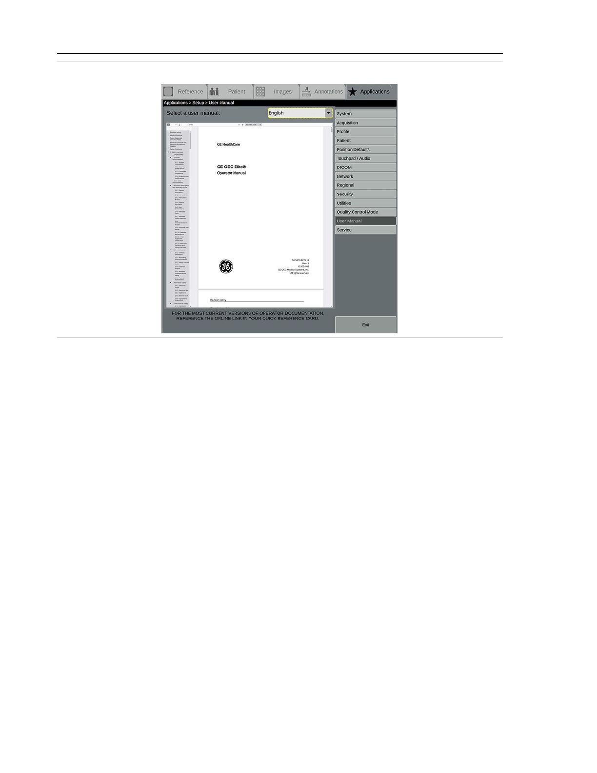
2. Touch the Applications tab and select Setup....
3. Touch User Manual. The User Manual screen with the default (English) manual displays.
4. From the drop-down list, select your language to open the User Manual or select to open
the Tips and Addendum.
1-5
Page 26
1 Safety overview
Figure 1-1: User Manual screen
1.5.1.2 Access the eIFUs on a PC
1. Insert the user manual USB device into a USB port on any USB-enabled device with PDF
reader capabilities.
2. Open the USB location and then open the appropriate PDF.
1.5.1.3 Use the eIFU PDF
l
Use the index on the left to select a section.
l
Use the scroll bar on the right to scroll through pages.
1.5.2 Replacement USB device
Any modifications to the files on the USB device can render them unreadable by your system. To
order a replacement USB device, call the Communications Center or your local sales
representative. See 13.1 Communication center contact information (page 13-1).
1.5.3 Online eIFU
The most current versions of operator documentation is available on the Internet.
To access the manuals online:
1. In a web browser, open https://www.gehealthcare.com/support/manuals.
2. Select English.
3. Click Browse by product and select:
1-6
Page 27

1 Safety overview
l
Modality: X-ray Surgery (XR)
l
Products: XR (Surgery) OEC Elite
4. Click Apply and then select User/Operation.
5. Click the Download icon to save the document to your computer.
6. Click Accept to accept the copyright terms and download the file.
1.5.4 Paper copies
A paper copy of the user manual can be ordered at no additional cost.
Send a request to your Sales or Service representative. They will transfer your request to gehc_
Per the EU Commission Regulation on electronic instructions for use of medical devices, in the
European Union, your request will be completed within seven calendar days.
1.6 General safety
Potential hazards exist in the use of medical electronic devices and X-ray systems. Operators using
the equipment should understand the safety issues, emergency procedures, and the operating
instructions provided.
The following pages describe hazardous and potentially hazardous conditions, and how to
adequately protect yourself and others from possible injury.
1.6.1 Contact information
Questions and comments regarding safety should be addressed to the OEC Medical Systems, Inc
service organization nearest them. Unresolved problems should be referred to:
Vice President, Quality Assurance
OEC Medical Systems, Inc
384 Wright Brothers Drive
Salt Lake City, Utah 84116
(801) 328-9300
See 9.3 Country and regional information (page 9-16).
1.6.2 Reporting serious incidents
Any serious incident related to the use of this device should be reported to both the manufacturer
and the health authority / competent authority where the device is installed.
To report to GE HealthCare, do one of the following:
l
Contact your local service representative, or
l
Send an email to [email protected].
1-7
Page 28
1 Safety overview
In you communication, include the following information:
l
The catalog number or the model designation of the device as stated on the identification
plate affixed on the device,
l
The System ID / serial number / lot number of the device,
l
The date of the incident,
l
A description of incident, including any patient or user impact or injury, and
l
Your contact information including facility, address, contact name, title, and telephone
number.
1.6.3 Safety hazard alerts
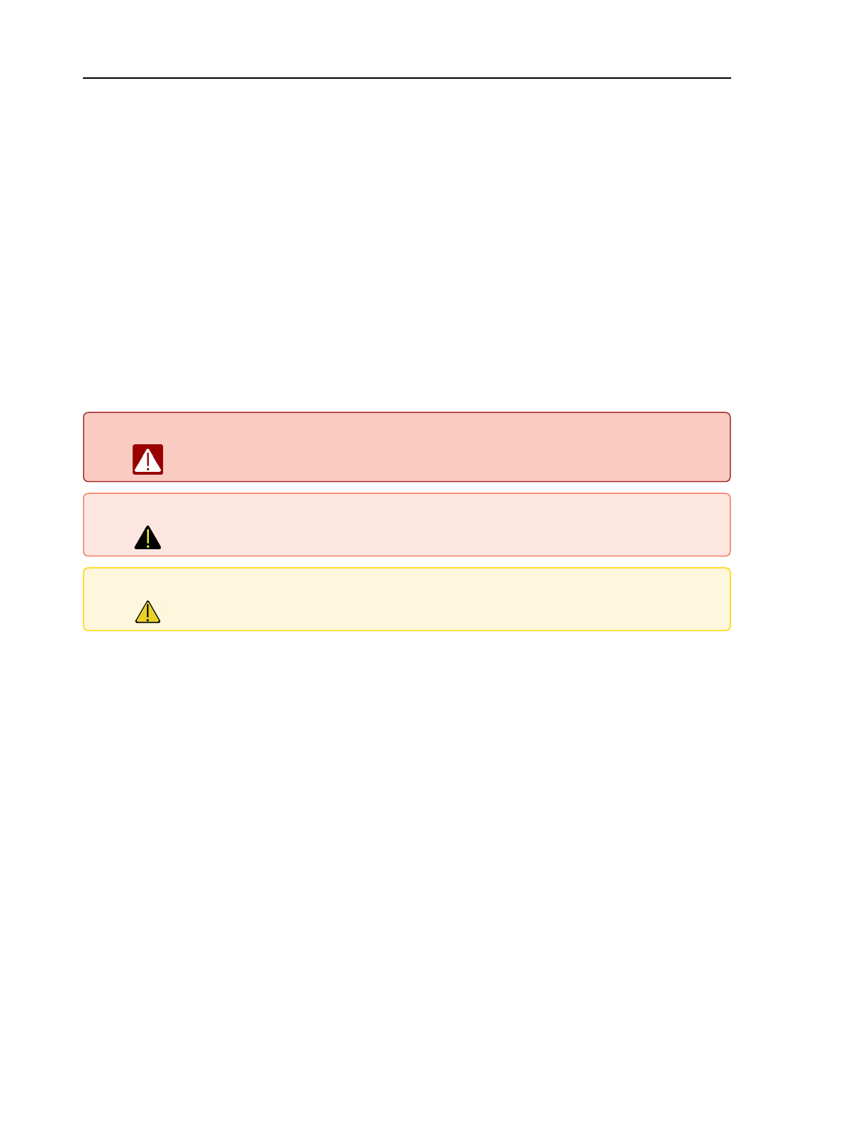
There are three hazard classifications, which are denoted and prioritized by the alert words:
Table 1-1: Hazard alert definitions
DANGER DANGER INDICATES AN IMMINENTLY HAZARDOUS SITUATION THAT, IF
NOT AVOIDED, WILL RESULT IN DEATH OR SERIOUS INJURY.
Warning Warning indicates a potentially hazardous situation that, if not avoided, could
result in death or serious injury.
Caution Caution indicates a potentially hazardous situation that, if not avoided, may
result in moderate to minor injury, equipment damage or loss of data.
1.6.4 External devices
To ensure patient safety, only connect external equipment that has been approved by OEC
Medical Systems, Inc All equipment attached to the external interface connections must meet the
requirements of IEC 60601-1 when operated within the patient environment. When used outside of
the patient environment, each externally connected device must comply with the relevant IEC/ISO
requirements for that device. In any case, the combination of all externally connected equipment
shall not cause the leakage current of any device used within the patient environment to exceed
the limits stated in IEC 60601-1.
1.6.4.1 Connection to a network
The system can be connected to a facility network. When connecting the system to a network, the
Responsible Organization must analyze, evaluate, and control potential risks or hazardous
situations that might occur due to failure of the network connection. This analysis should consider
network configuration changes, equipment added to or removed from the network, and updates
or upgrades. See 2.2.1.10 Set up security (page 2-53).
1-8
Page 29
1 Safety overview
1.6.5 Wireless compliance and safety
This device complies with the essential requirements and other relevant provisions of the Radio
Equipment Directive 2014/53/EU.
1.6.6 Viewing the RED Declaration of Conformity
1. Navigate to the Support Documentation Library
(https://www.gehealthcare.com/documentationlibrary) in a web browser.
2. Under the Customer Documentation Portal header, click VISIT THE SITE.
3. Once in the portal, enter RED DOC in Enter the document number or keyword field.
4. Click Browse by product.
5. Select X-ray Surgery (XR) from the Modality filter menu.
6. Select X-RAY (SURGERY) OEC ELITE from the Products filter menu.
7. Click Apply. The search results display.
8. Click the Download to the right of the document to save it to your computer.
This device complies with ACMA radio communications regulatory arrangements and mandatory
technical standards as required for Australia and New Zealand.
This device complies with Industry Canada license-exempt RSS standard(s). Operation is subject
to the following two conditions: (1) this device may not cause interference, and (2) this device
must accept any interference, including interference that might cause undesired operation of the
device. The IC number identifies the ISED certification number associated with the transmitter.
See Table 9-72 (page 9-19) information on the wireless certification label and symbols.
Caution Changes or modifications not expressly approved by the party responsible for
compliance could void the user’s authority to operate the equipment.
Note: Wireless LAN products using 802.11ax, 802.11ac, 802.11a, 802.11b, 802.11g, 802.11n, and
802.16e are designed for use only in specific countries, and may only be operated in
countries of designated use. The frequencies used by these devices might not yet be
harmonized in all countries.
It is the user's responsibility to ensure that this product is used only in country for which it is
intended and to verify that it is configured with the correct selection of frequency and
channel for the country where it is used. Any deviation from the permissible power and
frequency settings is an infringement of national law and may be punished as such.
1-9
Page 30
1 Safety overview
Note: This equipment has been tested and found to comply with the limits for a Class B digital
device, pursuant to Part 15 of the FCC Rules. These limits are designed to provide
reasonable protection against harmful interference in a residential installation. This
equipment generates uses and can radiate radio frequency energy and, if not installed and
used in accordance with the instructions, might cause harmful interference to radio
communications. However, there is no guarantee that interference will not occur in a
particular installation. If this equipment does cause harmful interference to radio or
television reception, which can be determined by turning the equipment off and on, the user
is encouraged to try to correct the interference by one of the following measures:
l
Reorient or relocate the receiving antenna.
l
Increase the separation between the equipment and receiver.
l
Connect the equipment into an outlet on a circuit different from that to which the
receiver is connected.
l
Consult the dealer or an experienced radio/TV technician for help.
“Harmful interference” is defined in 47 CFR §2.1 by the FCC as follows: Interference which
endangers the functioning of a radionavigation service or of other safety services or
seriously degrades, obstructs, or repeatedly interrupts a radio communication service
operating in accordance with the [ITU] Radio Regulations.
Note: To comply with FCC’s RF Exposure Safety Limits for general population / uncontrolled
exposure, the antenna(s) used for this transmitter must be installed to provide a separation
distance of at least 20 cm from all persons and must not be co-located or operating in
conjunction with any other antenna or transmitter.
This product is restricted to indoor use.
AT BE BG CH CY CZ DE DK EE EL ES FI FR HR HU IE IS
IT LI LT LU LV MT NL NO PL PT RO SE SI SK TR UK
1.6.7 Patient environment
1.6.7.1 United States
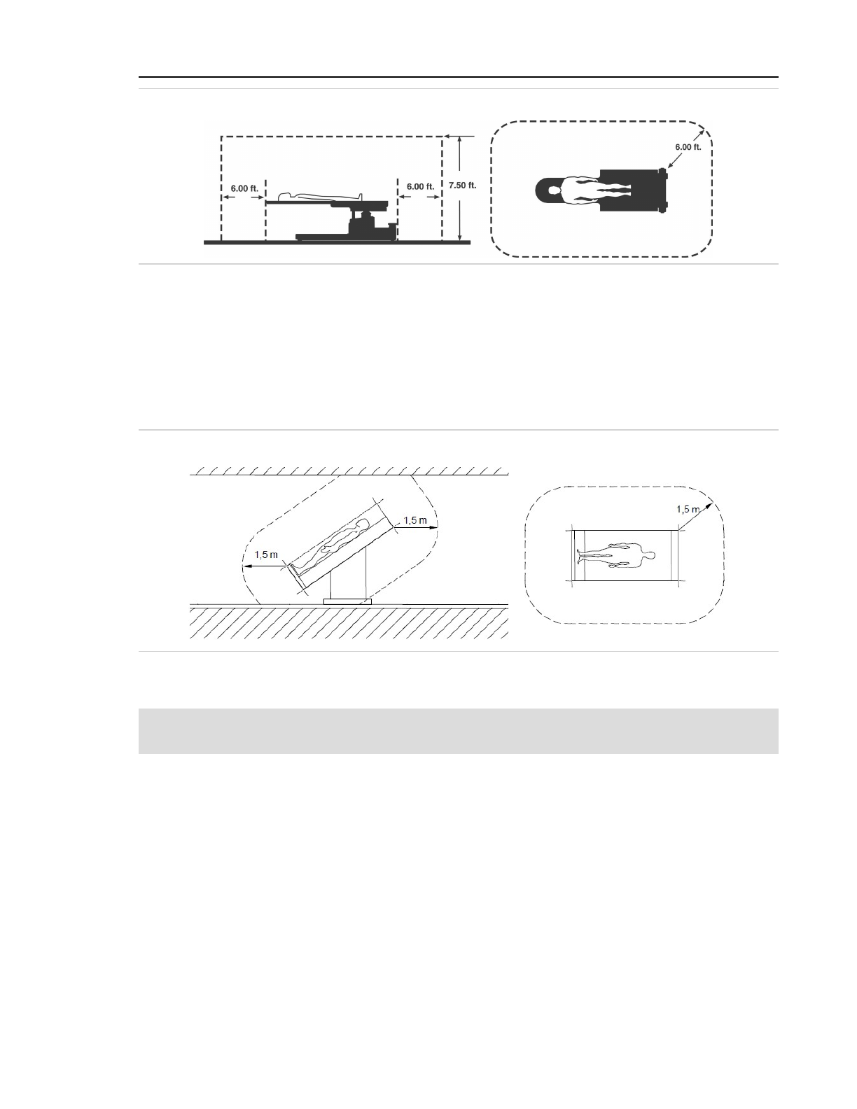
Within the US, the Patient Environment is defined by NFPA 99. In areas in which patients are
normally cared for, the patient environment is the space with surfaces likely to be contacted by
the patient or an attendant who can touch the patient.
This encloses a space within the room 6 ft. beyond the perimeter of the bed (examination table,
surgical table, treatment booth, and so on) in its intended location, and extending vertically 7.5 ft.
above the floor.
1-10
Page 31
1 Safety overview
Figure 1-2: US patient environment
1.6.7.2 International
In many international countries, the patient environment is defined by IEC 60601-1. In areas in
which patients are normally cared for, the patient environment is the space with surfaces likely to
be contacted by the patient or an attendant who can touch the patient.
This encloses a space within the room 1.5 m beyond the perimeter of the bed (examination table,
surgical table, treatment booth, and so on) in its intended location.
Figure 1-3: International patient environment
1.7 Electrical safety
Note: Any emergency procedure developed by the owner, for the area in which the system is used,
should include these safety measures.
1.7.1 Electrical shock
Observe the following safety procedures to avoid electric shock or serious injury to operators and
patients and to avoid system malfunction.
l
Make all electrical connections to equipment while outside the patient environment. Do not
touch a connector and the patient at the same time.
l
Do not bypass, jumper or otherwise disable the safety interlocks.
l
Do not remove any of the assembly covers.
1-11
Page 32
1 Safety overview
l
Do not place food or beverage containers on any part of the equipment. If spilled they can
cause short circuits.
l
Always remove power to the equipment before cleaning. See 10.1.1 Approved cleaning
agents / disinfectants (page 10-1).
l
Only qualified service engineers are allowed to service or repair a system.
Warning Electrical circuits inside the equipment may use voltages which are capable of
causing serious injury or death from electric shock. To avoid this hazard, never
remove any of the cabinet covers.
Warning To avoid the risk of electric shock, this equipment must only be connected to a
supply mains with protective earth.
1.7.2 Electrical fire
In the event of electrical fire on or near the system, perform the following emergency procedure:
1. Remove battery-backed power from the system by following the Immediate system
shutdown procedure (page 2-110)
2. Unplug the power cord from the AC receptacle.
3. Evacuate personnel from the area.
4. Only use a fire extinguisher that is approved for use on electrical fires.
5. Call your local fire department for help if necessary.
Warning The use of the wrong type of fire extinguisher presents electrical shock and burn
hazards. To avoid these hazards, a fire extinguisher which meets applicable
regulations and standards must be available in the room where the equipment is
being used. Remember that equipment that is equipped with batteries is a source
of electrical current, even when AC power is disconnected.
1.7.3 Explosion
The system is not rated for use in a flammable gas or oxygen-rich environment.
If an abnormal condition occurs, such as the room fills with flammable gas, take steps to prevent
the gas from coming in contact with the equipment. Follow these guidelines:
l
Do not turn the system off or unplug it from the AC receptacle.
l
Do not operate any other electrically powered equipment.
l
Evacuate all personnel from the area and ventilate with fresh air. Avoid operating any
automated (electrically operated) doors or windows.
l
Contact your local fire department as soon as possible.
1.7.4 Ground fault
If the operating room has a ground fault alarm and the alarm is actuated:
1-12
Page 33
1 Safety overview
l
Do not operate the system.
l
Call a qualified service technician.
1.7.5 Equipment malfunction
If either the hospital or equipment circuit breakers trip, an equipment malfunction might be
indicated. Do not attempt to operate the equipment until a qualified service engineer has checked
it.
If any of the equipment controls fail to respond as indicated in this manual, you should:
1. Remove power to the equipment by placing the power switch in the off position and
unplugging the power cord from the AC receptacle.
2. Notify a qualified service engineer.
3. Do not operate the equipment until the service technician advises that it is operating
properly.
1.8 Mechanical safety
1.8.1 Improperly attached equipment
If your equipment accommodates a Laser Aimer or some other piece of equipment that can be
attached or removed, follow these guidelines:
l
Use only equipment and accessories approved by OEC Medical Systems, Inc.
l
Read and follow all instructions for attaching and detaching equipment.
Warning Attach the equipment properly. Incorrectly attached equipment could fall,
causing injury to the patient or operator.
Note: See 13.35 Dimensions (page 13-38) for the correct dimensions of items that can be used in
conjunction with this product.
1.8.2 Equipment stability, transport, and positioning
If your system is mounted on wheels and casters and it is moved or operated improperly it could
roll out of control. Follow these guidelines:
l
Two people should maintain control of the equipment when moving up or down an incline.
l
Place all mechanical assemblies in their most compact (transport) position and lock brake
handles prior to moving the equipment.
l
Always lock the monitor assembly during transport.
l
Use the handles designed for moving the equipment and mechanical assemblies.
l
Never attempt to move the system up or down steps.
l
Do not operate the equipment on unlevel floors.
1-13
Page 34

1 Safety overview
l
Do not lock the wheel brakes and leave the equipment unattended on unlevel floors or
inclines.
l
Always apply the wheel locks when the system is in its final position.
l
Do not move the equipment if the casters or wheels are not functioning properly.
l
Moving or positioning while disk drives are accessing information might cause mechanical
shock damage to the disk drive.
1.8.3 Motorized and manual mechanical movement
This equipment has parts that move or can be moved during normal operation. Some parts
require manual activation, while others are activated using motors.
Observe the following safety guidelines:
l
Take care to avoid pinching hands, fingers, or other body parts when moving or positioning
the system.
l
Observe and prevent articles of clothing from getting caught in moving parts.
l
Always observe mechanical assemblies when operating the motor to avoid collision with a
person or object.
l
Use care when working around equipment to avoid unintentional motor actuation. Do not
carelessly place objects on the equipment or bump or lean against the equipment.
l
Ensure that motion locks are secure after mechanical movements to prevent unintended
motion or collision with a person or object.
l
Ensure that motion clutches are secure after motorized movements to prevent unintended
motion or collision with a person or object.
l
A motion stop button is provided on the RUI to stop motion immediately, if needed. See
Motion stop switch (page 3-116) for instructions and locations.
l
A fast stop switch is provided on the cross-arm housing to stop X-ray generation and motor
motions, if needed. See 3.3.4.1 Fast stop switches (page 3-94).
l
A bumper on the detector provides contact detection to stop motion if a collision occurs.
See 3.3.4.6 Contact detection (page 3-121).
1.8.4 Repetitive motion
The system is designed to reduce repetitive motion injury risks as much as is reasonably
practicable. When operating the system, follow work practices to further reduce these risks, such
as taking frequent breaks and varying motions.
1.8.5 Ingress of fluids
Caution The X-ray system is not rated for water-tight operation. If liquids drip into the
equipment, disconnect the power cord and do not operate the system until it can be
cleaned and inspected by a qualified service engineer.
1-14
Page 35
1 Safety overview
Excessive amounts of fluids such as antiseptics, cleaning solutions, or bodily fluids might damage
internal components if they are allowed inside the equipment and might require unplanned
service that is not covered by standard planned maintenance or service contract coverage. Use
drapes to protect equipment and do not apply excessive amounts of fluid when cleaning.
1.8.6 Draping
Cover the C-Arm using a sterile draping system during use. Avoid positioning non-sterile C-Arm
components in the sterile field. Replace drapes after each use.
Custom fit, single-use sterile drapes specifically designed for OEC C-Arms can be purchased from
GE HealthCare. See 13.1 Communication center contact information (page 13-1).
Refer to the instructions provided with the draping system for details on how to drape the system.
Note: Use of a footswitch cover is recommended during all medical procedures.
Draping the X-ray tube housing inhibits air flow resulting in cooling inefficiencies. This might result
in the housing reaching its rated heat capacity sooner. A message displays, indicating the
temperature of the housing. When the housing reaches its maximum rated heat capacity, X-rays
are disabled until the housing has cooled. See HOUSING OVERHEATED, X-RAYS DISABLED Restart
the system. (page 11-43).
Caution Avoid covering the X-ray tube’s ventilation holes or system vents with a drape or other
obstruction. The system may overheat, resulting in downtime while the system cools.
1.8.6.1 Draping the X-ray tube cooling kit
When an X-ray tube cooling kit is installed (on applicable models), a fan and vents are added to
increase air flow to the X-ray tube housing. Covering the vents in the high voltage cable cover with
drapes prevents the fan from cooling the X-ray tube housing as designed.
1.8.7 Cooling efficiency
Draping some parts of the X-ray equipment might restrict airflow to components that provide heat
sinking and to vents designed to cool the equipment. Drape equipment and cover vents only
when exposure to excessive fluids is unavoidable and extended use of the equipment is not
required.
1.8.8 Contact Burns
Warning Extended use of imaging equipment may cause components such as X-ray tubes
to reach temperatures capable of inflicting burns. Use care when positioning
equipment to avoid placing hot components on or in close proximity to patients
and personnel. An anesthetized or unconscious patient is incapable of sensing
and reacting to a hot component. See 13.21 Maximum surface temperatures
(page 13-17) .
1-15
Page 36
1 Safety overview
1.9 Radiation safety
Warning This equipment either produces or is used in the vicinity of ionizing radiation.
Risks and dangers are inherent in the operation of this equipment, and exposure
to radiation can have both short-term deterministic and long-term stochastic
effects, including skin injury, hair loss, and increased risk of cancer. This
equipment should only be used by personnel properly trained and authorized in
the use of ionizing radiation. Observe proper safety practices during equipment
operation.
1.9.1 Designated use areas
This equipment should be used only in areas that are suitable for safe operation. These areas
should provide radiation protection from stray scatter radiation outside the equipment use area,
and be properly marked, indicating that ionizing radiation might be in use in the area.
1.9.2 Personal radiation protection
Ensure that all personnel wear appropriate protective clothing, such as lead aprons, thyroid
shields, glasses, and radiation monitoring devices, and use protective devices such as lead shields,
stands, curtains, and so on, while using the equipment or working in the area around the
equipment. See 13.31 Isokerma maps of stray radiation (page 13-22). Take care that operators and
other personnel do not put hands, arms, or other body parts in the X-ray beam. Always stand as
far as possible from the X-ray tube when generating X-rays.
Consult with local radiation officials for specific radiation protection guidance.
1.9.3 Patient radiation protection
Exercise care in patient and equipment positioning to minimize the amount of radiation needed
for diagnosis and treatment. Use appropriate protective shielding and covers over patient
anatomy that is not part of the area to be imaged. Select X-ray techniques and imaging modes
that maximize imaging capabilities while minimizing the amount of radiation delivered to the
patient. See 4.4 Patient / exam radiation display (page 4-21).
1.9.4 Radiation indicators
Remain alert for visual indicators and audible alarms that are activated when ionizing radiation is
being produced by equipment in the work area. Yellow indicator lights illuminate when X-rays are
being produced. An audible rhythmic beeping tone is emitted at the initiation of X-rays, and
continues throughout the duration of the radiation exposure. See 5.1.6.1 Visual and audible X-ray
indication (page 5-9).
1.9.5 Radiation burns
High levels of radiation directed at the same patient skin area for a prolonged period of time
might cause deterministic effect skin burns. To minimize this absorbed dose to the patient, use
reduced dose techniques or reorient the X-ray beam in relation to the patient anatomy whenever
1-16
Page 37
1 Safety overview
possible. See 4.4 Patient / exam radiation display (page 4-21).
1.9.6 Source-to-skin distance
Caution The patient should be positioned as far away from the X-ray source as possible in
order to keep the absorbed dose to the patient as low as reasonably achievable.
Regulations specify that a minimum source-to-skin distance (SSD) be maintained, with a reduced
distance exception for special surgical procedures. The system maintains a minimum source-to-
skin distance of 30 cm when the skin spacer is attached to the collimator cover. Where allowed,
the skin spacer can be removed for special procedures. When removed, the collimator cover
maintains a minimum source-to-skin distance of 20 cm.
Warning Removing the skin spacer may result in increased radiation exposure to the
patient. The rate of exposure increases exponentially as the anatomy is
positioned closer to the X-ray tube. The skin spacer should only be removed on
the instructions of a physician, and should be reattached to the collimator cover
immediately following the procedure. See 3.1.5 Skin spacer (page 3-11).
1.9.7 Patient supports
Objects in the beam, such as tables and patient supports, might cause the imaging system to
increase the amount of radiation in order to obtain an optimal image of the patient. Minimize
additional exposure by removing unnecessary objects from the path of the X-ray beam or by using
accessories designed for use in X-ray beams.
1.9.8 Radiation fast stops
Radiation fast stop switches located on the cross-arm housing are provided to stop X-rays
immediately if needed. Pressing a red fast stop switch immediately stops X-ray generation and
motor motions. If the fast stop switch is activated, ensure that no hazard exists before resetting
the switch. See 3.3.4.1 Fast stop switches (page 3-94).
1.9.9 Imaging pediatric or smaller patients
Radiation exposure is a concern in both adults and children. However, children are more sensitive
to radiation than adults and have a longer post-exam life expectancy, so particular attention
should be paid to the displayed dose values and alarms. Radiation risk is higher in young patients,
as they have more rapidly dividing cells than adults. Using the same exposure parameters on a
child as is used on an adult might result in unnecessarily large doses to the child.
C-Arm settings can be adjusted to reduce dose significantly while maintaining diagnostic image
quality. GEHC suggests reducing radiation dose to as low as reasonably achievable for all patients,
especially for pediatric and small patients.
Use the following suggestions to reduce the amount of radiation that pediatrics and small
patients receive from fluoroscopic examinations
1-17
Page 38

1 Safety overview
l
Perform only necessary fluoroscopic examinations. The indications and the appropriate
technique to be used should be reviewed by the physician / surgeon prior to every exam,
including the number of previous medical X-ray examinations, reasons for the fluoroscopic
procedure, and consideration of other effective lower dose modalities. In all circumstances,
the expected benefits of the fluoroscopic procedure must exceed the overall risk.
l
Image only the anatomical region indicated. Limit imaging coverage to the anatomical
region of the body indicated to avoid unnecessary exposure.
l
Obtain only clinically necessary image quality. Limit images requiring the highest
radiation dose to very specific procedures or procedure steps.
Radiation dose reduction must be balanced with safe, accurate, and effective procedures. The
goal is to minimize the dose to the patient, providing important and necessary medical care while
maximizing patient safety. Not all steps listed below might be possible, depending on patient size,
technical challenge, critical nature, and type of procedure.
1. Remove the anti-scatter grid when performing examinations on small patients.See 3.1.6
Anti-scatter grid (page 3-13).
2. Use the Pediatric profile, which utilizes a lower dose optimized for small patients. This
profile provides image processing and is optimized for versatility, creating the best possible
images over a wide range of uses.
3. Before beginning the procedure, and during the procedure as conditions and field of view
change, consider the collimator position and aperture size.
4. Use the Low Dose function. Low Dose automatically decreases the calculated ABS or
manually entered technique to less than or equal to one half the dose rate. See 3.3.2.9 Low
Dose (page 3-86) and 5.6.7 Low dose (page 5-32).
5. Keep the skin spacer installed to keep the minimum distance between the patient and X-
Ray focal spot.
6. Adjust acquisition parameters to achieve lowest dose necessary to accomplish the
procedure.
7. Position the C-Arm over the area of interest, using the Laser Aimer to aid in proper
positioning. This helps avoid extra positioning shots. See 3.1.7 Laser Aimer (page 3-16).
8. Keep the image detector as close as possible to patient.
9. Minimize use of magnification modes. Instead, use the zoom feature when possible. See
3.3.3.7 Zoom (page 3-91).
10. Position and size the collimator using the Collimator Leaf Rotation, Collimator Leaf
Open/Close, and Collimator Iris Open / Close keys. See 3.3.2.5 Collimator Leaf Rotation
(page 3-84), 3.3.2.7 Collimator Leaf Open / Close (page 3-85), and 3.3.2.6 Collimator Iris Open /
Close (page 3-85). If necessary, perform a brief fluoroscopy to check position.
11. Collimate as tightly as possible to the area of interest, taking care to exclude the eyes,
thyroid, breasts, and gonads, when possible.
12. Use the Pulse function with as low a pulse rate as possible, rather than continuous
fluoroscopy. See 3.3.2.8 Pulse (page 3-85) Information on changing the pulse rates is
contained within the sections detailing pulsed modes later in this chapter.
1-18
Page 39

1 Safety overview
13. Briefly press the X-ray pedal or button, and review the anatomy and record information
using last image hold, rather than with live fluoroscopy.
14. Utilize the DICOM RDSR to establish a site imaging dose review process.
15. Ensure that the equipment is checked regularly by a physicist or designee with appropriate
skills.
The information in this section is adapted from the Alliance for Radiation Safety in Pediatrics
Imaging’s Image Gently website. For more information about pediatric patient safety in
fluoroscopy and other X-ray emitting technologies you can consult the following online resources:
l
Image Gently (https://www.imagegently.org)
l
Image Wisely (Radiation Safety in Adult Medical Imaging) (https://www.imagewisely.org)
l
Society of Pediatric Radiology (SPR) (https://www.spr.org/)
l
American Association of Physicists in Medicine (AAPM) (https://www.aapm.org)
l
American College of Radiology (ACR) (https://www.acr.org)
l
Pediatric X-ray imaging information on the FDA website (https://www.fda.gov)
l
International Atomic Energy Association’s Radiation Protection of Patients
(https://rpop.iaea.org)
1.9.10 Deterministic effects of ionizing radiation on humans
During normal use of an X-ray system, there is a risk that dose levels might occur that have
deterministic effects on humans. The risk of occurrence increases with procedures that require
higher dose levels (high kV and mA) and/or are of prolonged duration.
CAK is useful in predicting short-term deterministic effects from radiation. Examples of
deterministic effects include skin injury and hair loss. The United States Food and Drug
Administration (FDA) in “Recording Information in the Patient's Medical Record That Identifies the
Potential for Serious X-ray-Induced Skin Injuries,” (1995), suggests a threshold of 1 Gy, beyond
which deterministic effects might appear. The International Commission on Radiological
Protection (ICRP) in "Avoidance of Radiation Injuries From Medical Interventional Procedures
(ICRP Publication 85)(2000) suggests a threshold of 2 Gy beyond which deterministic effects might
appear.
It is possible, in all Fluoroscopy modes, to reach deterministic thresholds of radiation if the
radiation exposure goes long enough. For most typical fluoroscopic procedures the dose to
patient is low and the risk of injury is low. Complicated interventional procedures of prolonged
duration might reach and exceed the deterministic level threshold. To avoid reaching this
threshold, use reduced dose techniques or reorient the X-ray beam in relation to the patient
anatomy whenever possible.
Use the Image Acquisition setup screen to select a CAK limit commensurate with the local and the
hospital’s thresholds of radiation. Then, when the CAK limit is exceeded, a CUMULATIVE AIR
KERMA LIMIT EXCEEDED message displays in the status bar. See 2.2.1.2 Set up image acquisition
(page 2-17) for information on selecting a CAK limit.
1-19
Page 40

1 Safety overview
See Appendix C: Dose rates (page C-1) for information on typical AKR dose rates related to specific
modes of operation and techniques under specific conditions.
See 13.30 Zones of occupancy (page 13-21) for information on typical dose rates to the operator.
1.10 Electromagnetic compatibility
All OEC C-Arm models generate and use radio frequency energy and must be installed and used
according to the manufacturer’s instructions in order to avoid receiving radio frequency
interference. If this equipment generates or receives interference do the following to correct the
problem:
l
Verify that the equipment is the cause by turning the system on and off.
l
In the event of unintended motor actuation, immediately remove power to the equipment.
l
In the event of unintended X-ray actuation, immediately remove power to the equipment.
l
Reorient the equipment until the interference stops.
l
Relocate the equipment with respect to other equipment in the room.
l
Plug the equipment into a different outlet so that the equipment and the receiver are on
different branch circuits.
l
Use only input/output (I/O) cables supplied by OEC Medical Systems, Inc
Mobile imaging equipment has the potential to emit electromagnetic radiation that might
interfere with the safe operation of other medical equipment. Conversely, other medical
equipment, including RF communications equipment, might emit electromagnetic radiation that
interferes with the mobile imaging system.
See 13.32 Electromagnetic emission specifications (page 13-31) for Emission Compliance level and
limits and Immunity Compliance level and recommendations to help the equipment keep its
clinical utility.
Systems containing a wireless transmitter generate elevated levels of radio frequency energy at
specific frequencies during normal operation. See 13.11 Wireless Card (page 13-6) for transmission
frequencies and energy levels of the wireless transmitter.
Note: All cables that are used to connect to the DVI and D-Sub connector I/O ports of the system
must be shielded cables or cables supplied by OEC Medical Systems, Inc
1.10.1 Performance criteria
The system is designed to perform its intended function during normal operation. In the presence
of electromagnetic interference, some degradation of displayed live video might occur but the
system returns to normal operation when the interference is eliminated. Any loss of function is
readily apparent to the operator and will not cause a safety hazard. Electromagnetic interference
will not cause permanent damage to the system.
1-20
Page 41
1 Safety overview
1.10.1.1 Degraded electromagnetic compatibility
Warning The use of accessories, transducers, and cables other than those specified may
result in increased emissions, or decreased immunity, or degraded
electromagnetic compatibility of the equipment and/or system.
1.10.1.2 System use in the vicinity of other equipment
The system should not be used adjacent to or stacked with other equipment; if adjacent or
stacked use is necessary, the system should be observed to verify normal operation in the
configuration in which it will be used.
1.11 Patient privacy and data security
If a system is to be left operating while unattended, or operated around unauthorized persons,
such as in an emergency room, enable the following HIPAA security measures to protect patient
privacy.
l
Set up a system password to prevent unauthorized access of patient data. See 2.2.1.10 Set
up security (page 2-53) for how to set up and 2.3.2.3 Password and log in (page 2-104) for
how to use this function.
l
Use the Blank button to clear the screens and prevent unauthorized persons from seeing
patient data. See 3.3.1.9 Blank button (page 3-81) for details on this function.
l
Place the system in Standby mode. The operator should remove the key from the keyswitch
and keep the key with them at all times to prevent unauthorized motion and X-rays. See
5.5.6 Keyswitch positions (page 5-24) for how to use this function.
l
If the device is connected to a network, the network should be private and inaccessible by
unauthorized personnel, including patients and the general public.
Note: All names appearing in example screens in this manual are fictitious. Any resemblance to
real people, living or dead is purely coincidental.
1-21
Page 42

1-22
1 Safety overview
This page intentionally left blank.
Page 43

2 System setup
2 System setup
This chapter covers the basic hardware and software setup as well as basics of starting up the
system, shutting it down, and restarting it.
Note: Main system screens includes a breadcrumb trail at the top of the screen to help navigation.
Refer to the screen images or the Glossary (page G-1) for the complete breadcrumb trail.
Screens might vary depending on system configuration.
2.1 System Overview
This section describes how to set up the system for initial use.
2.1.1 Moving the main system components
Caution Familiarize yourself with the location and mechanical operation of all controls prior to
moving the system.
Note: In order to avoid premature or unnecessary wear and tear of cables attached to the system,
pay special attention to the cables and avoid running over them with carts or other
equipment.
2.1.1.1 Move the Workstation
This section is for OEC Elite systems only and does not apply to OEC Elite ECO / SCO
systems.
Use the following procedure to move the Workstation, including into and away from a patient
location.
1. Verify that the Workstation is completely shut down.
2. Unplug the Workstation power cord. Wrap and secure the cable around the power cable
hangers.
3. Disconnect the interconnect cable from the C-Arm and wrap it around the Workstation
interconnect cable hangers.
4. Disconnect any other external connections.
5. Motorized systems only: Stow the RUI in the tray at the rear of the Workstation, and wind
the cable around the Workstation handle to secure it. Do not transport the RUI together
with the C-Arm.
2-1
Page 44
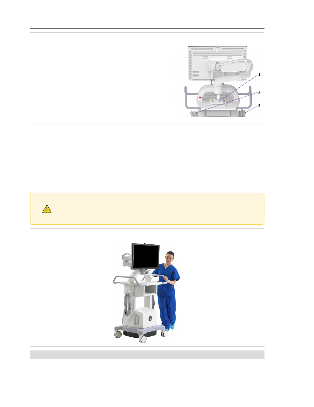
2 System setup
Figure 2-1: Rear of the Workstation prepared for movement
1. RUI stowed on the rear of the workstation
2. Workstation power cable hangers
3. Workstation interconnect cable hangers
6. Using the monitor handle, face the monitor to the front and lock it into the monitor latch.
See Figure 2-8: Monitor from front in latched position (page 2-7). Make sure hands and
fingers are clear when latching the monitor to avoid pinching.
7. Unlock the wheel brakes on the Workstation, and place the brake in the appropriate
position, as described in Figure 2-12: Workstation brake pedal (page 2-10).
8. Guide the Workstation to its destination using the handles, as shown in Figure 2-2: Moving
the Workstation (page 2-2).
9. When you reach your destination, apply the wheel brakes on the Workstation.
Caution Two people should maintain control of the Workstation when moving up or down an
incline. Do not move the Workstation over inclines greater than 10°. Do not move the
Workstation up or down stairs or steps. Do not lock the Workstation in place on an
incline greater than 5°.
Figure 2-2: Moving the Workstation
Note: The monitor enclosure should be checked for damage if the system collides with any object.
2-2
Page 45
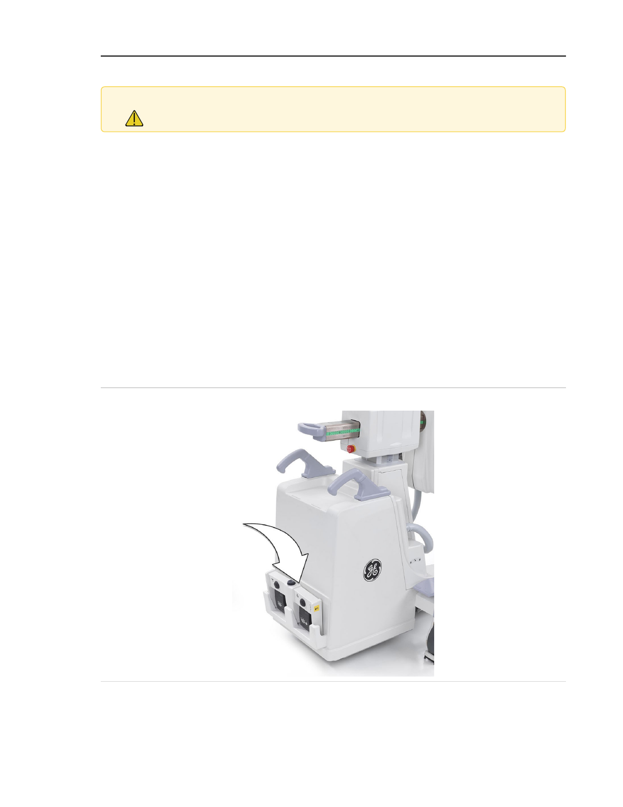
2 System setup
2.1.1.2 Move the C-Arm
Caution Use the handles provided on the C-Arm to position mechanical assemblies. The
handles are provided for your safety.
1. Return all moving assemblies to their most compact positions. Lower the vertical column
and retract the cross-arm.
a. Motorized systems only: Place the C-Arm in the 0,0 position.
b. OEC Elite ECO / SCO systems only: Position the touchscreen monitor in the monitor
cradle and apply the monitor arm break. See 2.1.2.2 OEC Elite ECO / SCO monitor
(page 2-7).
2. Lock all movable mechanical assembly brakes: the C-Arm lateral rotation brake, the
cephalad / caudal tilt brake, the Wig-wag brake, and the horizontal cross-arm brake.
3. Remove all power from the system.
4. OEC Elite systems only: Disconnect the interconnect cable from the C-Arm and wrap it
around the Workstation interconnect cable hangers. See Figure 2-1: Rear of the Workstation
prepared for movement (page 2-2).
5. OEC Elite ECO / SCO systems only: Wrap the power cord around the system power cable
hangers.
6. Store the footswitch on the rack located on the rear of the C-Arm and store the handswitch
in the holster located on the C-Arm's left front cover.
Figure 2-3: Footswitch stored in rack on rear of C-Arm
7. Place the C-Arm's right steering handle in the 0° position and unlock the wheel brakes.
8. Guide the C-Arm by pushing with the steering handles, or by pulling with the positioning
handles.
2-3
Page 46
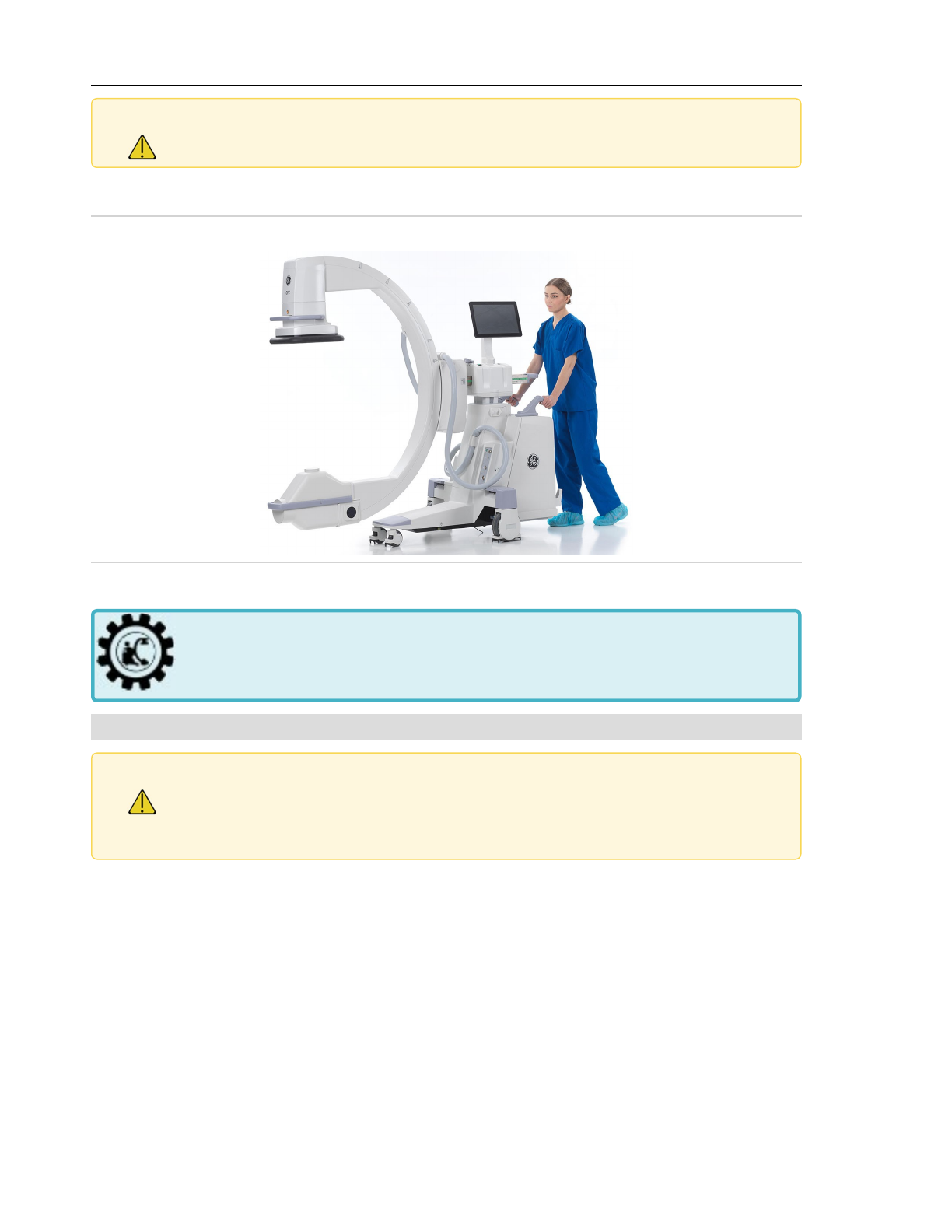
2 System setup
Caution Do not move the C-Arm over inclines greater than 10°. Do not move the C-Arm up or
down stairs or steps. Do not lock the C-Arm in place on an incline greater than 5°.
9. When you reach your destination place the C-Arm’s wheel brakes in the locked position.
Figure 2-4: Moving the C-Arm
RUI holder
This section is for motorized systems only.
Note: Some systems have an RUI holder, allowing the RUI to be attached during transport.
Caution The RUI holder will move up and down with the C-Arm lift column.
Pinch points exist between the RUI holder and the C-Arm base. Ensure hands, fingers
and objects are clear of the area between the RUI holder and the C-Arm base when
adjusting the C-Arm lift column.
The RUI holder is intended to secure the RUI to the C-Arm for transportation.
Secure the RUI to the RUI holder
1. Unlatch the clamp under the RUI .
2. Affix the clamp to the table rail shaped interface.
3. Secure the clamp of the RUI so it is affixed to the RUI holder.
Always store the cable for transport.
2-4
Page 47
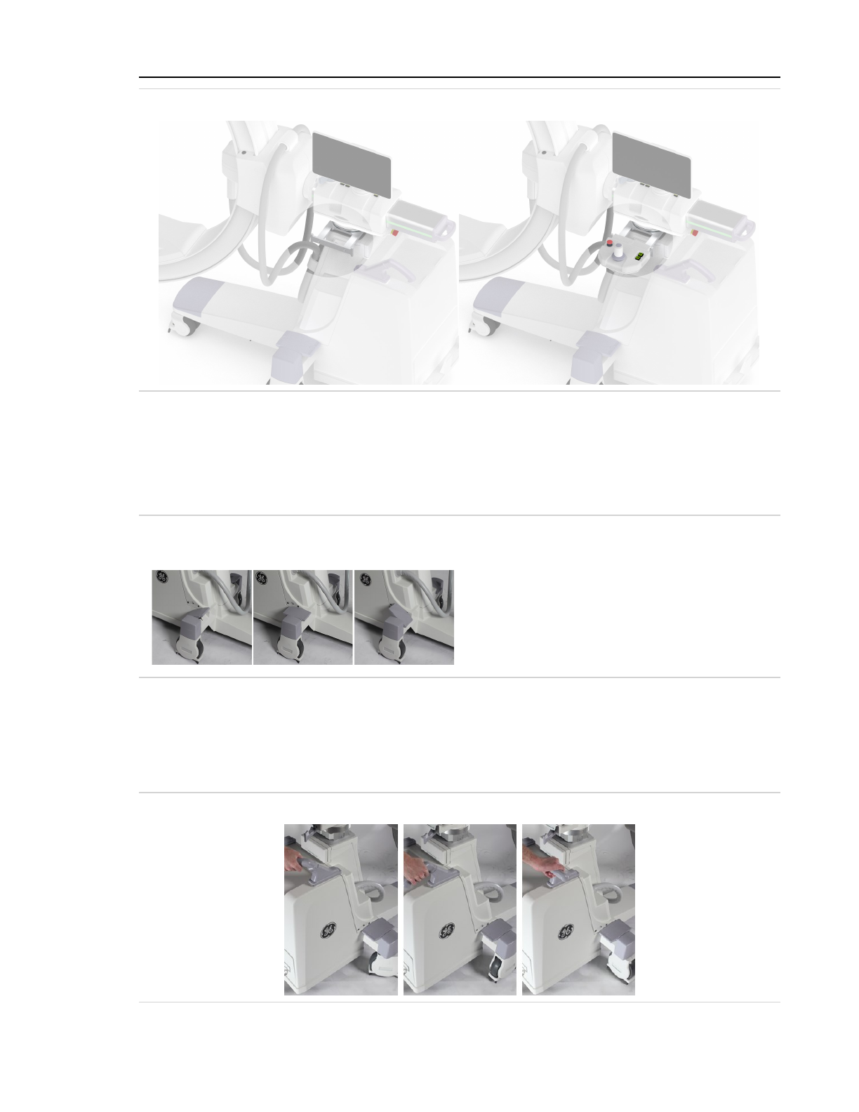
2 System setup
Figure 2-5: RUI holder without RUI (left) and with the RUI (right)
C-Arm wheel brakes
The C-Arm brake pedals are located above the rear wheels on both sides of the C-Arm. The pedals
operate much like rocker switches.
The pedal positions are:
Figure 2-6: C-Arm brake pedal positions
1 2 3
1. Locks the rear wheel brakes.
2. Unlocks the rear wheel brakes allowing
the wheels to rotate freely.
3. Locks the rear wheel brakes.
C-Arm steering handle
Use the right steering handle to turn the rear wheels from 0° to 90° to the right or left. Use this
feature to position the C-Arm during clinical applications or to negotiate sharp turns during
transport. The rear wheels turn at approximately the same angle as the right steering handle.
Figure 2-7: Right steering handle
2-5
Page 48
2 System setup
Caution To avoid losing control of the C-Arm, always reduce transport speed before moving
the steering handle out of the 0° position.
Caution If the Wig-wag brake is set to the extreme right, use caution not to injure your
knuckles when turning the steering handle 90° to the left.
Note: The rear wheels can be positioned in this manner whether the brakes are applied or not.
2.1.2 System monitors
The main system monitor can be positioned and tilted for optimal viewing.
Caution Only use the monitor handle to position the monitor. Pulling on other parts of the
monitor assembly to position the monitor could damage the monitor assembly.
Caution Do not hang on, lean on, or load the monitor arm. Doing so may cause a tip hazard.
Caution Do not position the monitor in a high traffic area.
Caution Do not drape cables over the monitor or monitor arm. Pulling a cable draped over the
monitor assembly could cause the monitor to move unexpectedly.
Caution Make sure hands and fingers are clear when latching the monitor to avoid pinching.
Note: The monitor might become warm to the touch after extended use. This is normal.
2.1.2.1 OEC Elite Workstation monitor
This section is for OEC Elite systems only and does not apply to OEC Elite ECO / SCO
systems.
2-6
Page 49
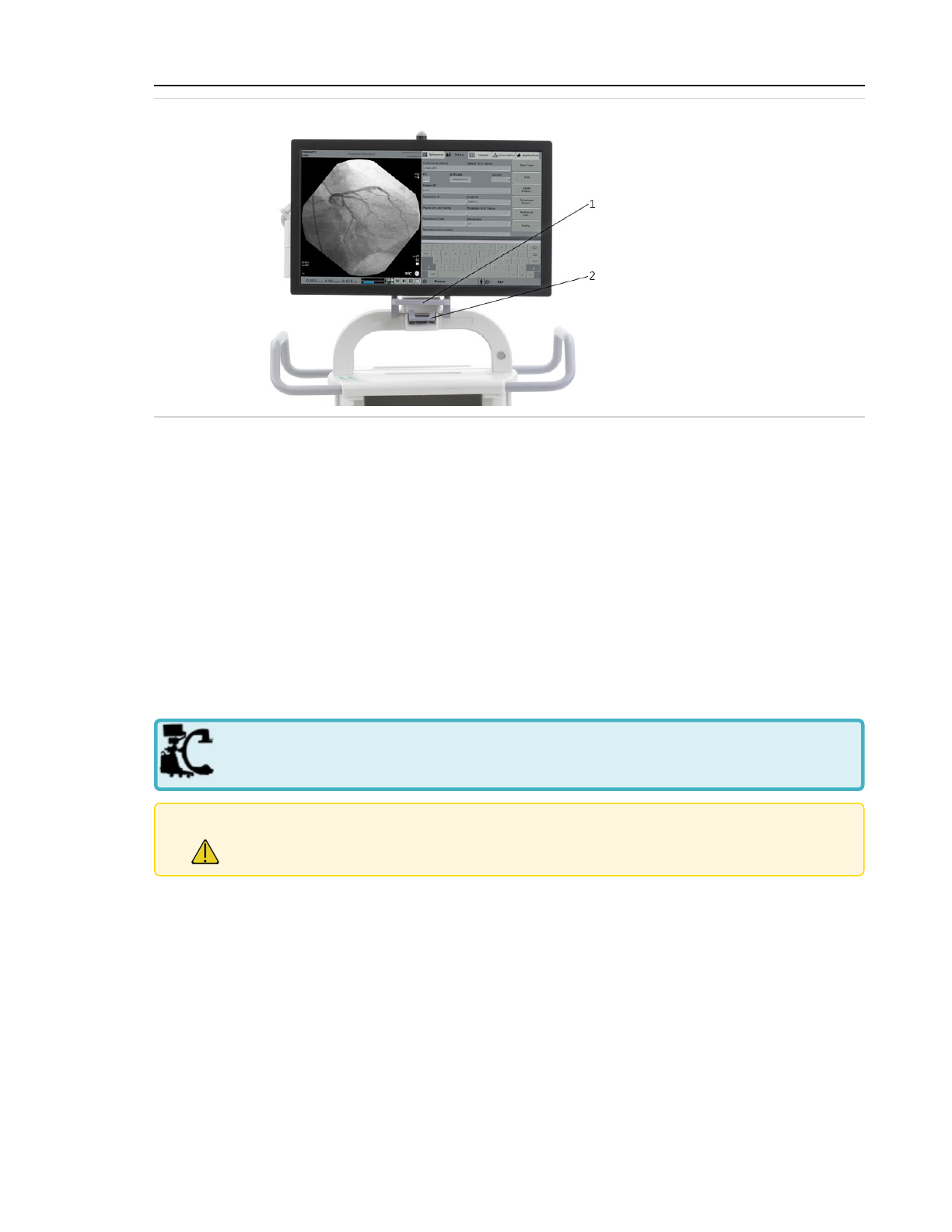
2 System setup
Figure 2-8: Monitor from front in latched position
1. Monitor handle
2. Monitor latch
Position the monitor
1. Press down on the monitor latch to release the monitor.
2. Using the monitor handle at the bottom front of the monitor, move the monitor to the
desired location and position. The monitor can be tilted side to side and top to bottom to
change the viewing angle.
Stow the monitor
1. Using the monitor handle at the bottom front of the monitor, move the monitor to face
front, pressing down into the monitor latch.
2. Press the latching bar into the monitor latch until it locks in place.
2.1.2.2 OEC Elite ECO / SCO monitor
This section is for ECO / SCO systems only and does not apply to OEC Elite systems.
Caution Because the system monitor can be freely moved, be aware of its position at all times.
Negligence can result in an unwanted movement or collision with the C-Arm and
personnel. This can cause personal injury or damage to the system.
2-7
Page 50
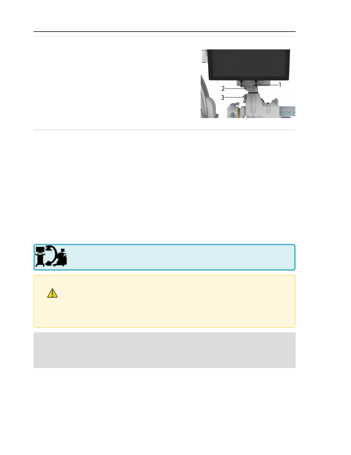
2 System setup
Figure 2-9: OEC Elite ECO / SCO monitor in cradled position
1. Monitor cradle catch
2. Monitor cradle
3. Monitor arm brake
Position the monitor
1. Grab the monitor by the handles, if present, and gently move the monitor to the desired
location and position. The monitor can be tilted side to side and top to bottom to change
the viewing angle.
2. Secure the monitor in place by using the monitor arm brake.
3. Place the monitor in the cradle before moving the monitor to either side of the C-Arm.
Stow the monitor
1. Move the monitor down into the monitor cradle.
2. Secure the monitor using the monitor arm brake.
2.1.3 Workstation overview
This section is for OEC Elite systems only and does not apply to OEC Elite ECO / SCO
systems.
Caution The GEHC Workstation should only be used in conjunction with a compatible and
appropriately configured GEHC C-Arm or as a stand-alone system. Damage may occur
if you connect the Workstation to an incompatible C-Arm or other equipment. This
Workstation is compatible only with GEHC C-Arms. If the Workstation is connected to
an incompatible C-Arm or other equipment, a message displays and Workstation will
not operate.
Note: Each C-Arm and Workstation is marked with colored system pairing labels that correspond
on compatible components. System pairing labels can be yellow, green, purple, red, orange,
blue, or indigo. Always match the system pairing labels before connecting a Workstation and
a C-Arm.
If the Workstation is used as an independent Workstation to review or navigate on previously
captured images, plug it into an active, compatible AC receptacle and turn the Workstation on.
2-8
Page 51
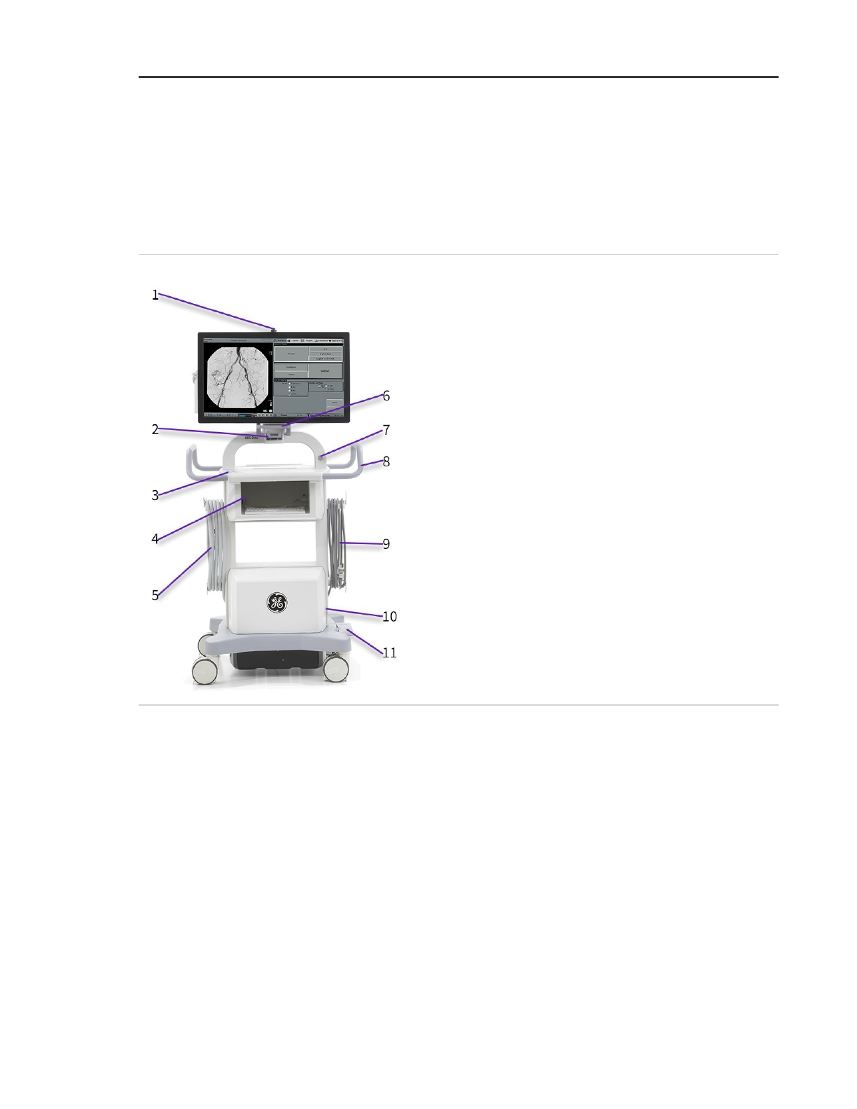
2 System setup
If the Workstation is to be used with a compatible C-Arm, connect the Interconnect Cable from the
Workstation to the C-Arm and check it for proper operation. The system does not need to be shut
down to disconnect or connect a C-Arm to the Workstation. When the interconnect cable is
disconnected while the system is running, there is a 10-second wait period before power is
applied to the C-Arm. If the interconnect cable is connected within that 10-second wait period,
power is not applied to the C-Arm until the wait period is complete.
The following illustration and list show the location of Workstation components.
Figure 2-10: Workstation components
1. X-Ray On indicator
2. Monitor latch
3. Image control keypad
4. Printer shelf
5. Interconnect cable, wrapped on cable hanger
6. Monitor handle
7. Power switch (green illuminated button)
8. Workstation handle
9. Power cord, wrapped on cable hanger
10. Fan vents (one on each side)
11. Workstation brake pedal
The Workstation back panel has a green indicator light that illuminates when the Workstation
receives AC line power from an active electrical outlet.
Circuit breakers are located below the green indicator light and on the right side of the back
panel. See 2.3.2 Turn on the system (page 2-98) for more details on each circuit breaker.
2-9
Page 52
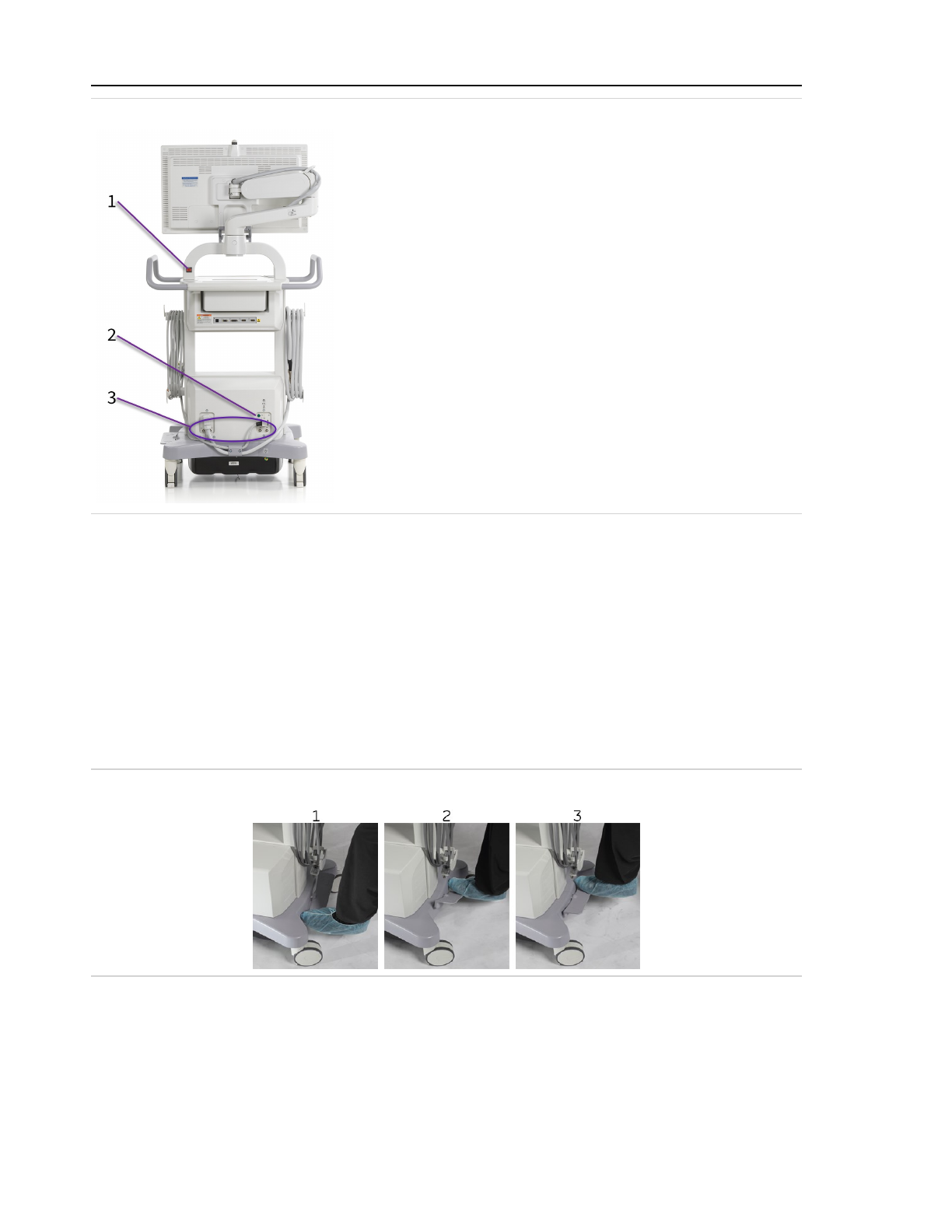
2 System setup
Figure 2-11: Workstation back panel
1. System disable switch
2. Illuminated green indicator light
3. Circuit breakers
2.1.3.1 Brake pedal
The Workstation brake pedal has three positions that control wheel movement. The pedal is
located on the left side of the Workstation. The pedal positions are:
1. Fully locked position: None of the wheels can roll or pivot.
2. Steering position: The wheels close to the pedal roll in a straight line, and the wheels
opposite pivot freely. Place the brake pedal in this position to move the Workstation long
distances.
3. Free movement position: All wheels pivot freely. Place the brake pedal in this position to
easily maneuver the Workstation during final positioning.
Figure 2-12: Workstation brake pedal
2.1.4 External connections
These warnings apply to the ports on the system as well as any connectors not in use on other
medical devices, such as printers, that are connected to the system.
2-10
Page 53
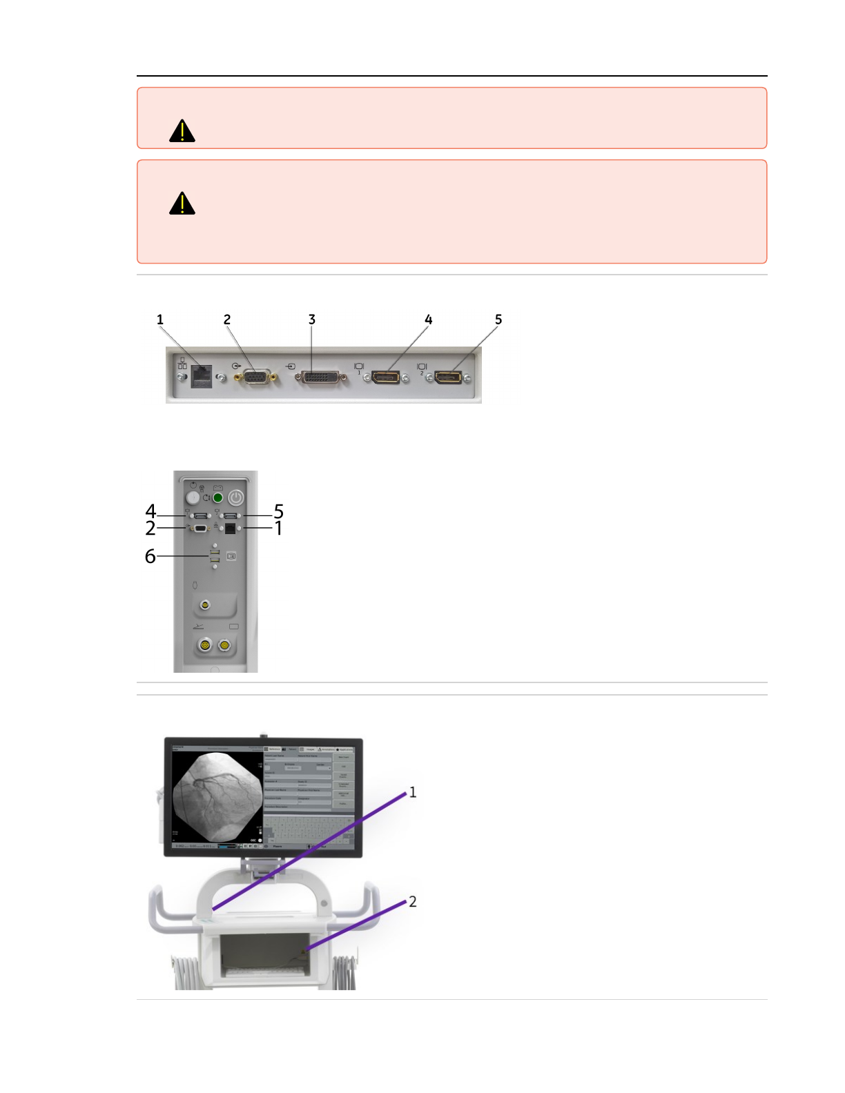
2 System setup
Warning Do not touch connectors and patient simultaneously. Electric shock could occur.
Warning Connect only medical devices that comply with UL/IEC 60601 Standards.
Contact GE HealthCare for a list of compliant devices.
Connecting a non-compliant device could cause injury to the operator, the
patient, or the equipment.
Figure 2-13: Workstation Interface panel and External ports
Figure 2-14: OEC Elite ECO / SCO Interface panel and external
ports
1. DICOM / Ethernet
network port(RJ45)
2. Room interface port
3. Video-in (DVI-D)
connector
4. Video-out (DisplayPort)
port - 1
5. Video-out (DisplayPort)
port - 2
6. USB Ports
Figure 2-15: Workstation USB port locations
1. Two USB ports inside
Workstation yoke
2. One USB port inside printer shelf
2-11
Page 54
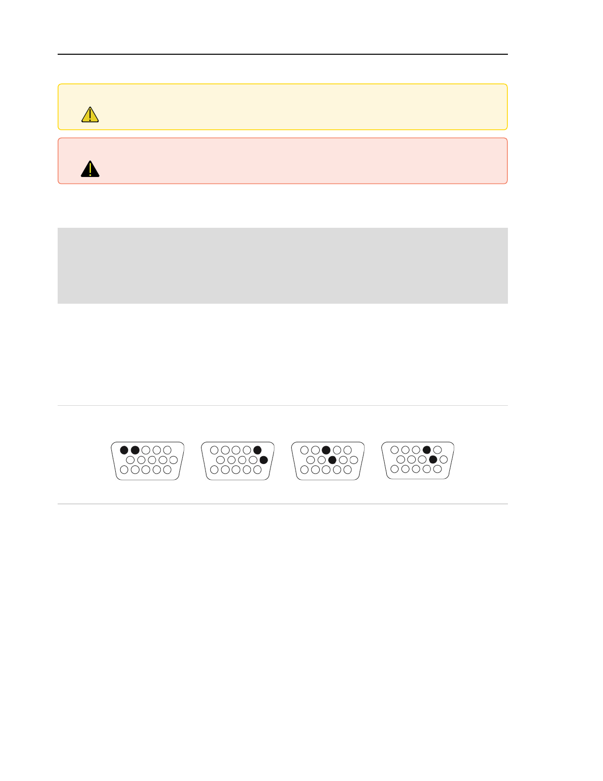
2 System setup
2.1.4.1 Connect a device to an external connector
Caution Because the system monitor can be freely moved, be aware of its position at all times.
Negligence can result in an unwanted movement or collision with the C-Arm and
personnel. This can cause personal injury or damage to the system.
Warning Connect only shielded cables or cables supplied by GEHC. When connecting
accessories, verify normal operation in the configuration in which the accessory
will be used.
Plug in external devices to the system, using the appropriate connection, as shown in Figure 2-13:
Workstation Interface panel and External ports (page 2-11) or 2.1.4 External connections (page 2-10).
Note: The system can provide a signal to an approved injector through the Room Interface port.
This signal is sent when the Syringe icon displays during Subtract procedures, and when the
system sends a signal during HLF with Cine and Digital Cine Pulse procedures. A custom
cable must be constructed or obtained from an approved injector manufacturer or OEC
Medical Systems, Inc
2.1.4.2 Room Interface connector
The Room Interface connector can communicate with various devices, including a Room In Use
sign, an X-Rays On lamp, a contrast agent injector, and a Door Open controller. The relays are
capable of switching 24V DC or 24V AC at a current of up to 2 amps.
2-12 shows a diagram of the pin numbers on the external connection that controls each signal.
Figure 2-16: Input/Output relay connections
Door Interlock Injector Room In Use Room X-Rays On
Pins 4 and 5 Pins 1 and 6 Pins 3 and 8 Pins 2 and 7
Door Interlock
This signal prevents X-rays from being produced when the room door is open.
If the system will not produce X-rays when the door is closed but produces X-rays when the door
is open, the system might be configured incorrectly for the room door's switch. Call for service.
Injector
This controls a power contrast injection connector output. A signal is sent when the Syringe icon
displays during a Subtract procedure. See 5.7.4 Contrast agent injector (page 5-38) for details on
using a power contrast injector.
Call Technical Support for a list of approved injectors that work with the system.See 13.1
Communication center contact information (page 13-1).
2-12
Page 55
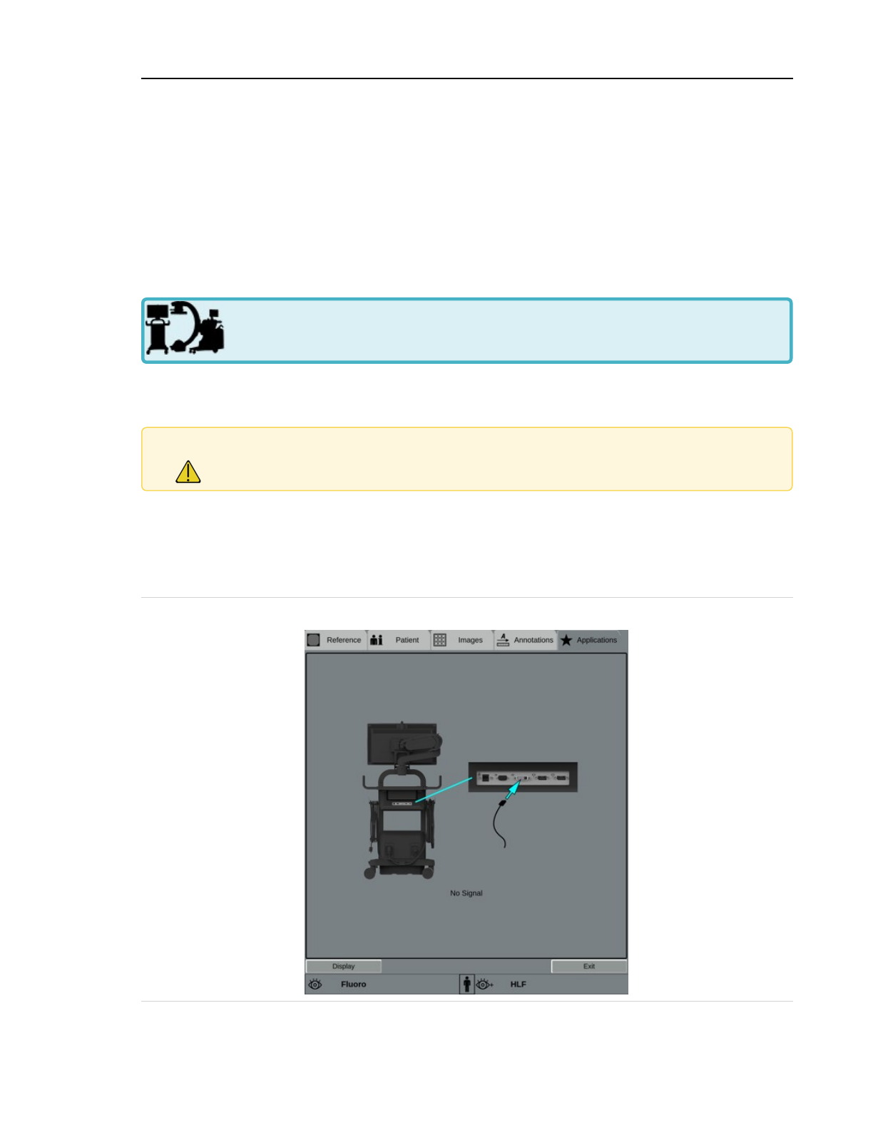
2 System setup
Room In Use sign
This signal controls a Room In Use sign. When the system is turned on and ready to take X-rays,
the Room In Use light illuminates.
Room X-Rays On lamp
This signal controls a Room X-Rays On lamp. When X-rays are being produced, the Room X-Rays
On lamp illuminates. It does not pulse with pulsed X-rays.
2.1.5 Connect and view external video
This section is for OEC Elite systems only and does not apply to OEC Elite ECO / SCO
systems.
The external video port provides a means of viewing an external video source (for example, an
endoscope) on the system monitor by a DVI-D connection.
Caution Position external video cables to avoid trip, catch, and snag hazards. The assembly
could move unexpectedly if external video cables are pulled.
1. Plug the external device into the Video-in (DVI-D) connector, shown in 2.1.4 External
connections (page 2-10).
2. Touch the Applications tab.
3. Touch External Video.... The External Video screen displays.
Figure 2-17: External Video screen
2-13
Page 56
2 System setup
Note: If no external device is connected, this screen still displays. Connect an external video device
as instructed in step 1, above.
4. Touch Display. The external video displays on the right side of the main system monitor.
5. Touch Exit to stop the external video display, and then disconnect the external video
source.
Caution Clean the external connector area with dry cloths only. Do not use liquid cleaners on
this area.
2.2 First time software setup
The first time the system is set up or after an extended time in storage, the batteries in the UPS
need several hours to charge before the UPS can be completely effective in case of an unexpected
power loss.
Charging of the UPS batteries begins automatically when the system is plugged in and does not
affect operation.
The C-Arm could require several hours to charge its batteries after the system is plugged in
initially or after an extended period in storage.
Note: For more information on C-Arm charge times and requirements, refer to the information on
powering on and battery charging in 2.3.2 Turn on the system (page 2-98).
2.2.1 Setup screens overview
This section explains how to tailor system operations to your specific requirements. Use these
screens to configure how decimals display, enable auto features, and set defaults, time and date,
and alarm tones, and so on. These settings apply when the system is started and when a new
exam is started, and should be set up before using the system for the first time.
Some features are not available on all systems.
Touch the Applications tab. The Applications screen displays.
2-14
Page 57
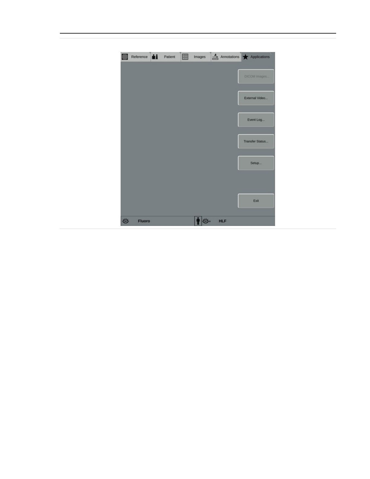
2 System setup
Figure 2-18: Applications screen
Use the buttons on the right side of this screen to access setup screens and set up system
features. Options available on the Applications screen are DICOM Images..., External Video...,
Event Log..., Transfer Status..., and Setup.... See 8.10 DICOM image viewer application (page 8-
40), 2.1.5 Connect and view external video (page 2-13), 11.1.2 Event logs (page 11-1), 11.1.3 Transfer
status (page 11-3), and 2.2.1.1 System setup screens (page 2-15).
2.2.1.1 System setup screens
Touch Setup... to display the main Setup screen. By default, the main Setup screen displays
system, hardware and software information, and current connectivity.
X-rays are disabled when the Setup screens are being configured.
Use the menu items on the right side of this screen to access setup screens and set up system
features.
2-15
Page 58
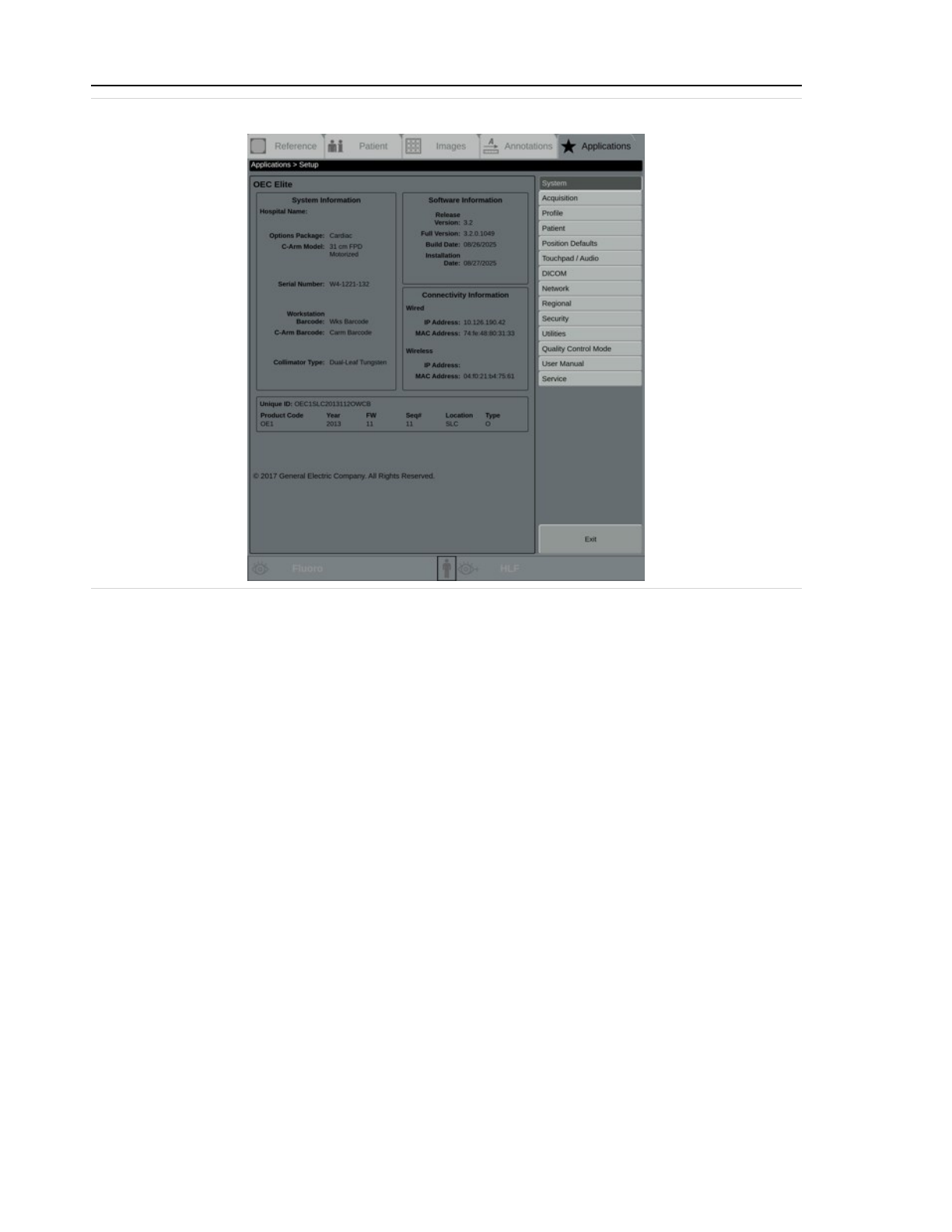
2 System setup
Figure 2-19: Main Setup screen with menu on the right side
OEC Elite
System Information
Displays the system's Hospital Name, installed Options Package, Workstation Barcode
and C-Arm Barcode, Collimator Type, and Options Enabled. Use this information when
determining compatibility and certain settings and options.
Software Information
Displays the system's software Release Version, Full Version, Build Date, and Installation
Date. Use this information when determining compatibility and certain settings and options.
Connectivity Information
Displays the system's wired and/or wireless IP Address and MAC Address information. Use
this information for networking and DICOM setup.
Hardware Information
Displays the system hardware components and their versions.
Identification Information
Displays the system's Unique ID and other system's manufacture information.
Touch Exit to return to the main Applications screen from any of the system option screens, or to
the previous screen from any submenu screens. If settings have been changed but not saved, a
message displays. Follow the message instructions.
2-16
Page 59

2 System setup
2.2.1.2 Set up image acquisition
Use the Image Acquisition screen to set up automatic save, swap, cine playback, mini cine
playback, Smart Metal and Fluorostore/Replay default functionality, and to select dose, pulse rate,
high level controls, HLF, vascular settings, CAK alarm limits, X-ray termination, and default
landmark percentage settings.
Touch Acquisition in the menu to display the Image Acquisition setup screen.
Figure 2-20: Image Acquisition setup screen
Default Settings
Auto Swap at Beginning of Exposure
Select this check box to automatically move live images to the right side of the main system
monitor when the image is created. Clear the check box to require users to swap images
manually.
Auto Save at End of Exposure
Select this check box to automatically save static images as soon as the X-ray switch is
released. Clear the check box to require users to save images manually. Note that Roadmap
phase 1 always saves even if auto save is disabled because it is necessary to save an image
for Roadmap to work correctly.
Auto Playback When Cine Acquired
Select this check box to automatically begin cine playback as soon as the cine is acquired.
Clear the check box to require users to play cine runs manually.
2-17
Page 60

2 System setup
Use Mini Cine Playback
Select this check box to automatically begin cine playback in the mini cine viewer as soon
as the cine is complete. Clear the check box to use the full cine viewer. If Auto Playback
When Cine Acquired is cleared, users must start cine playback manually.
Use Smart Metal
Select to enable metal rejection functionality and improve image quality when the patient's
body contains metal, such as dental fillings or internal hardware. Clear the check box to
turn off metal rejection.
Enable Fluorostore / Enable Replay
Select to enable Fluorostore or Replay, depending on the system configuration, to store the
last 300 frames of an unsaved shot which can then be reviewed as a cine. Clear the check
box to turn off Fluorostore or Replay. See 6.2.6 Fluorostore and replay (page 6-15).
Center Marking
Display Center Marker
Select this check box to display a center marker at the center of the field of view of LIH and
live images.
Brightness
Choose the brightness level of the center marker. Options are Low, Mid, and High.
Dose
Choose Standard Dose to improve image quality, or Low Dose to use a lower dose rate.
Pulse Rate
Choose 4 PPS, 8 PPS, or 15 PPS (pulses per second). Available options depend on the sys-
tem configuration.
High Level Control
Choose HLF, Digital Spot, or Digital Cine Pulse.
HLF generates X-rays at higher power output for denser anatomy and improves visu-
alizations while reducing X-ray exposure. Digital Spot generates X-rays at higher radiation
dose rates resulting in high quality imaging, and is often used for diagnostic interpretation.
HLF
Choose Armed, which allows HLF at any time, or Disarmed, which requires the user to arm
HLF before each HLF shot.
Vascular
Select a default mode for Vascular imaging. Choose Roadmap or Fluoro.
CAK Alarm Limit
Choose the Cumulative Air Kerma (CAK) alarm limit from 0.50 Gy to 2.50 Gy, in 0.25 incre-
ments.
2-18
Page 61

2 System setup
The CAK Alarm indicates when radiation exposure has exceeded the limit for an exam. Use
lower settings for pediatric use, or in situations where lower doses are preferred. Use higher
settings to allow higher dose before the alarm sounds.
Per regulations, the patient entrance reference point for Elite systems is 15cm from the iso
center in the direction of the x-ray source.
Shot Mode
Select Continuous to set the default shot mode to continuous imaging, or select Pulse to
set the default shot mode to pulsed imaging. By default, continuous imaging is the default
setting. The selection applies to new exams, but the user can change the shot mode during
the exam.
Contrast Selection
When negative (CO
2
) contrast is enabled on the system, choose Positive (e.g. Iodine) to set
the default contrast agent to a positive contrast agent, such as iodine, or Negative (e.g.
CO
2
) to set the default contrast agent to a negative contrast agent, such as CO
2
.
Vascular Mode Negative Contrast
When negative (CO
2
) contrast is enabled on the system, select Enable Negative Contrast
(e.g. CO
2
) to allow the user to enable negative contrast agent, such as CO
2
, or clear to only
allow positive contrast agents, such as iodine.
Terminate Short Exposure When
Depending on the service settings selected, one or more of the following might display.
Choose one. Contact Service if this setting needs to be changed. The actual limit of expos-
ure extension on very short “toe tap” exposures is dependent on the X-ray termination
mode selected:
l
Switch Released - Stops X-ray generation when the X-ray switch is released. Image
processing might be incomplete, which can reduce the quality of the image displayed.
l
Target Technique Reached - Stops X-ray generation as soon as the system reaches
the selected target technique, which might be after the X-ray switch is released.
l
Selected Noise Filter Applied - Stops X-ray generation when the selected level of
image processing has been applied to the image, which might be after the X-ray
switch is released. Note that maximum processing includes frame averaging, which
attempts to reduce noise effects in any one frame.
Landmark Percentage
Choose any value, from 0% to 100%.
Touch Save to save the settings or touch Exit to return to the main Applications screen. If settings
have been changed but not saved, a message displays. Follow the message instructions.
2.2.1.3 Set up default profile
Use the Default Profile screen to select the imaging profile that will be active when the system is
started and when a new exam is started.See 5.2 Anatomical profiles (page 5-9).
2-19
Page 62
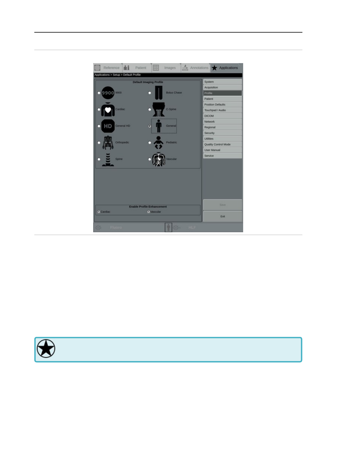
2 System setup
Touch Profile in the menu to display the Default Profile setup screen.
Figure 2-21: Default Profile setup screen
Touch a profile option on the Default Profile setup screen to select that imaging profile as the
default. See 5.2 Anatomical profiles (page 5-9)
Enable Profile Enhancement
Select to enable image enhancement. Select Cardiac to enable image enhancement when
using the Cardiac profile, and Vascular to enable image enhancement when using the Vas-
cular profile. Enhancement for these profiles is on by default.
Touch Save to save the settings or touch Exit to return to the main Applications screen. If settings
have been changed but not saved, a message displays. Follow the message instructions.
2.2.1.4 Set up patient information
Some system setup is limited to Administrative users only. Emergency and clinical users
do not have access to the screens and functions described in this section.
Use the Patient Information screen to define the data that displays in the image overlay, is saved
to DICOM, and is printed.
Touch Patient in the menu to display the Patient Information setup screen.
2-20
Page 63
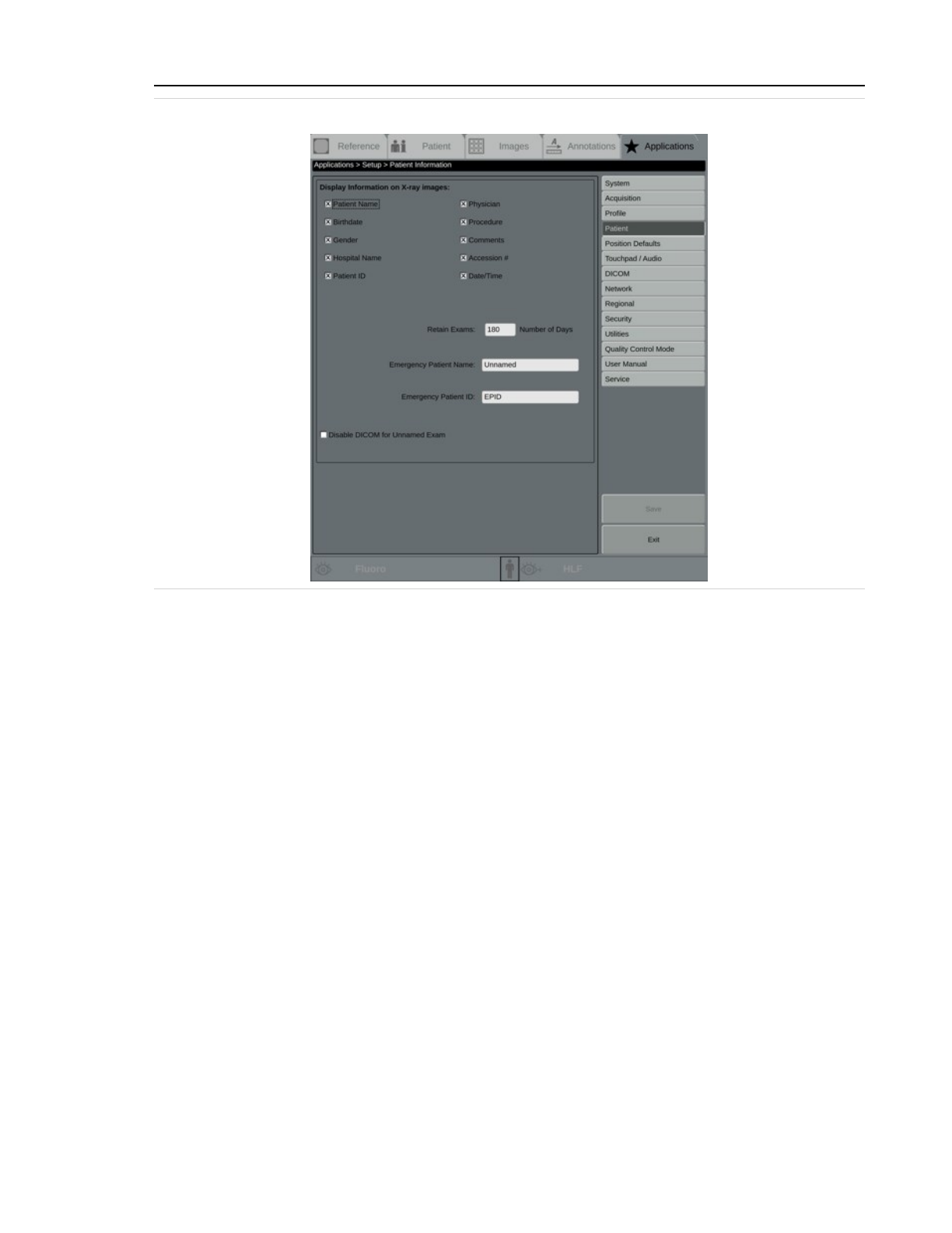
2 System setup
Figure 2-22: Patient Information setup screen
Display information on X-ray images
When a patient information category is selected here, the related patient information
entered in active boxes displays on left side of the main system monitor.
Select the check box for each Patient Information category that should appear on images,
or clear the check box to exclude that information from images.
Options include Patient Name, Birthdate, Gender, Hospital Name, Patient ID, Physician,
Procedure, Comments, Accession #, and Date/Time.
Retain Exams
Enter the default number of days to retain exams. Exams must be archived or manually
deleted. See 8.9 Delete exams and images (page 8-39) for details on archiving and deleting
exams.
Emergency Patient Information
Enter a name and ID for beginning exams for a new patient without entering full patient
information, for use in emergency situations. The system automatically adds a number so
that each emergency exams has a unique name.
Disable DICOM for Unnamed Exams
Select this check box to disable DICOM MPPS, Store, and Print messages from being sent for
emergency or unnamed exams.
2-21
Page 64
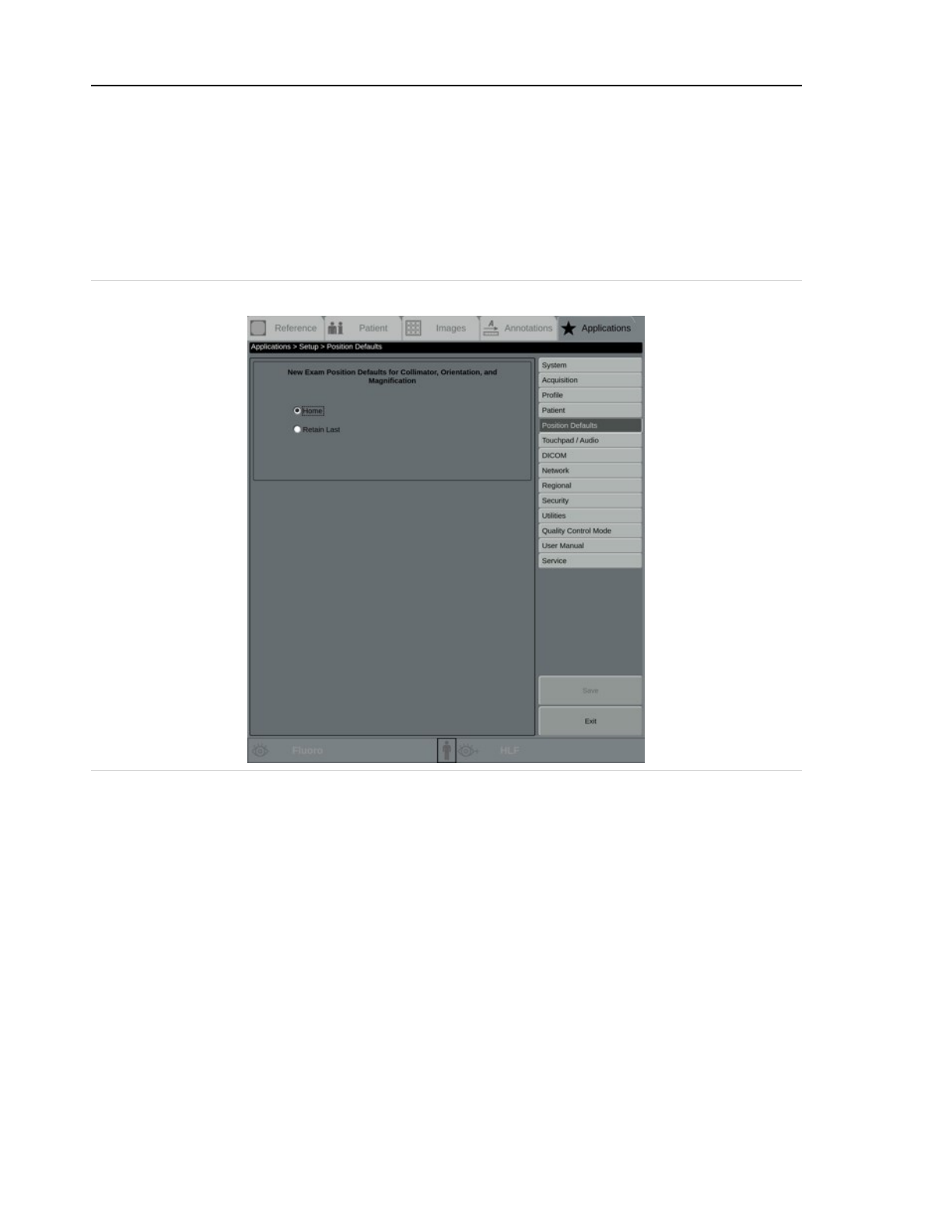
2 System setup
Touch Save to save the settings or touch Exit to return to the main Applications screen. If settings
have been changed but not saved, a message displays. Follow the message instructions.
2.2.1.5 Set up position defaults
Use the Position Defaults screen to set up the default positions for the system collimator,
rotation, and magnification for new exams.
Touch Position Defaults in the menu to display the Position Defaults setup screen.
Figure 2-23: Position Defaults setup screen
New Exam Position Defaults for Collimator, Orientation, and Magnification
Select Home to return to neutral position and normal magnification for each new exam.
Select Retain Last to retain the last used settings for each new exam.
Touch Save to save the settings or touch Exit to return to the main Applications screen. If settings
have been changed but not saved, a message displays. Follow the message instructions.
2.2.1.6 Set up touchpad and audio
Use the Touchpad / Audio screen to configure the mouse functions, touchpad operation, and
alarm pitch.
Touch Touchpad / Audio in the menu to display the Touchpad / Audio setup screen.
2-22
Page 65
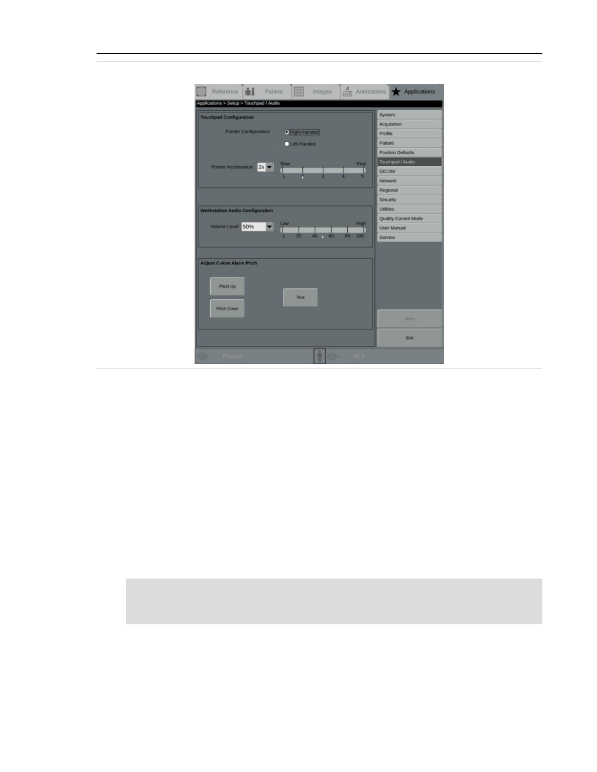
2 System setup
Figure 2-24: Touchpad / Audio setup screen
Touchpad Configuration
Pointer Configuration
Select Right-Handed or Left-Handed pointer configuration.
Pointer Acceleration
Select the pointer acceleration, from 1x (slowest) to 5x (fastest). Increasing acceleration
allows you to move the cursor from one side of the screen to the other with less motion on
the touchpad.
Workstation / System Audio Configuration
Volume Level
Select a volume level, from 1% to 100%, for system alerts, the shutdown sound, and key-
board clicks. When the level is changed, a test tone sounds.
Note: This does not control the volume of the OEC Touch / Touch Tableside. See Volume and
brightness control on the OEC Touch / Touch Tableside (page 3-112) for information on
controlling the C-Arm control panel beep volume.
Adjust C-Arm Alarm Pitch
Pitch Up
Touch to adjust the alarm pitch up. There are 18 distinct pitches.
2-23
Page 66
2 System setup
Pitch Down
Touch to adjust the alarm pitch down.
Test
Touch to hear the alarm pitch.
Note: X-rays are disabled while this screen is active.
Touch Save to save the settings and return to the Setup screen or touch Exit to return to the main
Applications screen. If settings have been changed but not saved, a message displays. Follow the
message instructions.
2.2.1.7 DICOM network setup
DICOM setup is limited to Administrative users only. DICOM setup is complicated and
should be performed by specialized IT personnel. Emergency and clinical users do not
have access to the screens and functions described in this section.
The system supports the DICOM (Digital Imaging and Communications in Medicine) standard for
handling, storing, printing, and transmitting information in medical imaging.
Use DICOM to print, store, and archive images, and to retrieve items from the worklist.
The American College of Radiology (ACR) and the National Electrical Manufacturers Association
(NEMA) developed the Digital Imaging and Communications in Medicine (DICOM) standard.
The standard uses an object-oriented design to query the worklist, archive, and print images.
During network transfers, both images and patient information are sent. This patient information
might be the result of a DICOM WorkList Query or it might be manually entered in the Patient
screen by the technologist. Patient birth dates can be part of the manually-entered patient data.
The system must be configured to access the DICOM network. Configuration identifies the system
to the network and defines DICOM network servers.
All devices that meet the DICOM standard are required to have a Conformance Statement that
defines how the device implements the standard. To configure devices, enter information
contained in the device's Conformance Statement or obtained from the local network
administrator.
Note: Network communications are always initiated by the system.
Note: The system supports 10 Base-T, 100 Base-T, and 1000 Base-T Ethernet connections.
Note: Main system screens includes a breadcrumb trail at the top of the screen to help navigation.
Refer to the screen images or the Glossary (page G-1) for the complete breadcrumb trail.
Screens might vary depending on system configuration.
2-24
Page 67
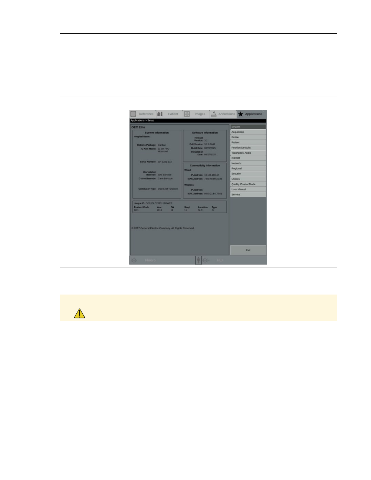
2 System setup
Set up DICOM network configurations
To set up network configurations, you must first connect your system to your facility's network.
See 2.2.1.8 Set up network configuration (page 2-41)
Touch the Applications tab and then touch Setup to display the Setup screen. A screen similar to
the following displays.
Figure 2-25: Setup screen with menu on the right side
Touch DICOM in the menu to display the DICOM screen and display the DICOM menu items on the
right side of the screen.
Caution Only qualified users should make changes to DICOM settings. Incorrect settings may
cause loss of DICOM functionality.
A screen similar to the following displays.
2-25
Page 68
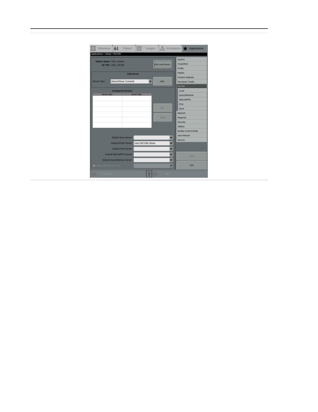
2 System setup
Figure 2-26: DICOM screen
Use the DICOM screen to edit existing DICOM servers, set up new DICOM servers, view configured
DICOM servers, and set up default DICOM settings.
If DICOM servers are already configured, the screen displays values in one or more of the fields.
Station Name
Displays the unique name, internal to the system, used to identify the server in the list of
available destination devices.
AE Title
Displays the DICOM Application Entity Title for the local server. AE Titles are limited to a
maximum of 16 characters, and are case-sensitive. This title is used for queries. The title
also is used by the Retrieve Server in response to store requests.
Edit Local Server...
Touch to change the local DICOM server settings. See Set up DICOM local server (page 2-28).
Add Server
If no servers are configured, or to add more servers, use this section to configure one or
more servers. A local server must be configured first.
Server Type
Select a server type from the menu. Options include Store / Store Commit, MWL / MPPS,
Query / Retrieve, and DICOM Print.
2-26
Page 69

2 System setup
Add...
Touch to add a new DICOM server of the selected type.
Configured Servers
Server Alias
Displays the server unique name for each configured server.
Server Type
Displays the server type for each configured server.
Edit...
Touch to edit a selected server.
Delete
Touch to delete a selected server.
Default Servers
Default Store Server
Displays the server alias for a configured store / store commit server. If more than one
server is configured, use the menu to select a default.
Default RDSR Server
Displays the server alias for a configured Radiation Dose Structured Report (RDSR) server. If
more than one server is configured, use the menu to select a default.
Default Print Server
Displays the server alias for a configured print server. If more than one server is configured,
use the menu to select a default.
Default MWL / MPPS Store Server
Displays the server alias for a configured Modality Work List (MWL) or Modality Performed
Procedure Step (MPPS) server. If more than one server is configured, use the menu to select
a default.
Default Query / Retrieve Server
Displays the server alias for a configured query / retrieve server. If more than one server is
configured, use the menu to select a default.
Enable DICOM Over TLS
Select to enable DICOM over TLS functionality on the system.
Certificate (unlabeled)
Select a certificate to use for DICOM over TLS.
Touch Save to save the settings. If no changes have been made, the Save button is unavailable.
2-27
Page 70
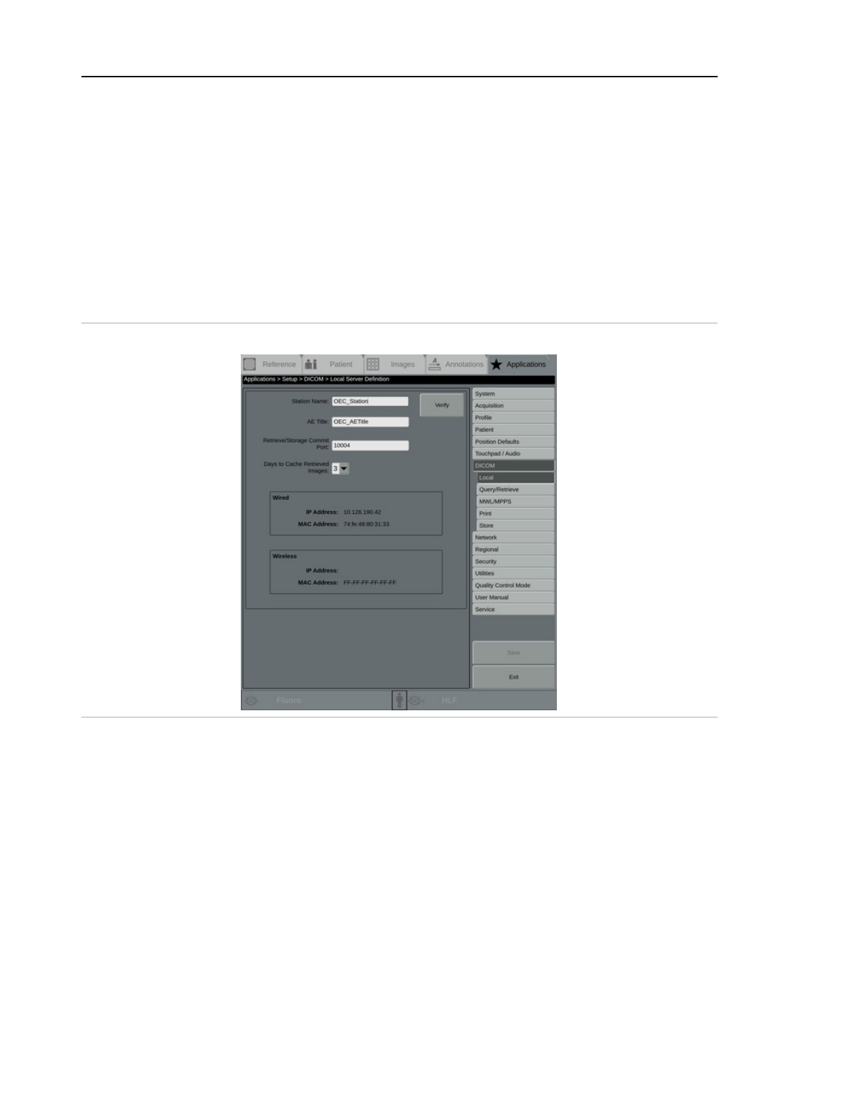
2 System setup
Touch Exit to return to the main Applications screen without saving any changes; a SAVE
CHANGES BEFORE EXITING? message displays. Follow the message instructions.
Set up DICOM local server
Use the Local Server Definition screen to set up a local server and image caching, and to view
wired and wireless local server information. A local server must be configured for other DICOM
services to function.
Obtain the values and information from a local network administrator.
On the DICOM screen, touch Edit Local Server..., or select Local from the menu. A screen similar
to the following displays.
Figure 2-27: Local Server Definition screen
Obtain the following information from the facility's network administrator or from the device's
DICOM Conformance Statement and enter it in on this screen:
Station Name
Enter the unique name, internal to the system, used to identify the server in the list of avail-
able destination devices.
AE Title
Enter the DICOM Application Entity Title. AE Titles are limited to a maximum of 16 char-
acters, and are case-sensitive. This title is used for queries. The title also is used by the
retrieve server in response to store requests.
2-28
Page 71

2 System setup
Retrieve / Storage Commit Port
Enter the port number assigned to the server running on the system. The default value is
10004. Valid values are 104 and 1025-49150.
Days to Cache Retrieved Images
Select the number of days, up to 7, that retrieved documents remain in the local cache. The
default is 3.
Wired
Displays the IP Address and MAC address for the wired network, if one is configured.
Wireless
Displays the IP Address and MAC address for the wireless network, if one is configured.
Verify
Touch to test that the settings are correct. If the system is not connected, a CANNOT MAKE
NETWORK CONNECTION message displays. Touch OK and follow the message instructions.
If the settings are correct and the system negotiates the network, a PORT VERIFICATION
SUCCESSFUL message displays. Touch OK to continue.
Otherwise, an INVALID PORT ENTRY OR PORT IN USE message displays. Touch OK to con-
tinue and then check the settings entered. If the settings are correct but the port veri-
fication fails, contact the facility's Network Administrator.
Touch Save to save the settings. If no changes have been made, the Save button is unavailable.
Touch Exit to return to the main Applications screen without saving any changes; a SAVE
CHANGES BEFORE EXITING? message displays. Follow the message instructions.
Set up DICOM MWL / MPPS server
Use the MWL / MPPS Server Definition screen to set up DICOM Modality Work List or Modality
Performed Procedure Step servers, which provide patient and exam schedule information from
the Radiology Information System (RIS).
On the DICOM screen, select MWL/MPPS from the Server Type menu, and touch Add..., or select
MWL/MPPS from the menu. A screen similar to the following displays.
2-29
Page 72
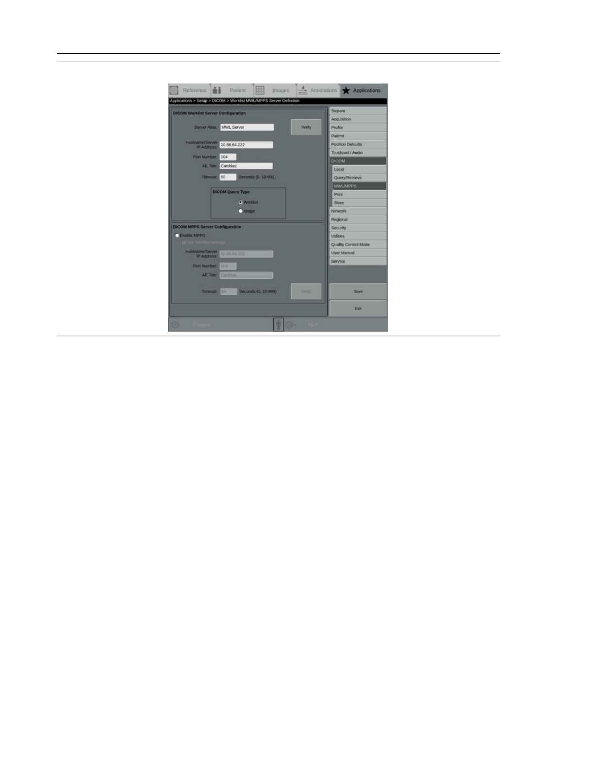
2 System setup
Figure 2-28: The MWL / MPPS Server Definition screen
DICOM Worklist Server Configuration
DICOM Query Type
Select the query type. Select Worklist to query the worklist data associated with a patient
or Image to query the metadata stored with the image.
In order to configure a DICOM MPPS Server, you must select Worklist.
DICOM MPPS Server Configuration
Enable MPPS
Select this check box to enable an MPPS (Modality Performed Procedure Step) server. If the
MPPS server settings are the same as the modality worklist, the rest of the fields are pop-
ulated automatically. Otherwise, obtain the following information from the facility's net-
work administrator or from the device's DICOM Conformance Statement and enter it in on
this screen.
Use Worklist Settings
Select this check box if the MPPS server settings are the same as the MWL settings. The rest
of the fields are populated automatically. Otherwise, leave this blank.
Hostname / Server IP Address
Enter the unique host name or IP address assigned to the configured server.
Port Number
Enter the port number assigned to the MPPS server. The default value is 104. Valid values
are 104, 1025-49000.
2-30
Page 73

2 System setup
AE Title
Enter the DICOM Application Entity Title. AE Titles are limited to a maximum of 16 char-
acters, and are case-sensitive.
Timeout
Select the maximum length of time to allow for transactions. Select 0 for no maximum time,
or select from 10 to 999 seconds.
Verify
Touch to test that the settings are correct. If the system is connected, a DICOM SERVER
VERIFIED SUCCESSFULLY message displays. Touch OK and follow the message instruc-
tions.
Otherwise, a VERIFY FAILED message displays. Touch OK to continue and then check the
settings entered. If the settings are correct but the verification fails, contact the facility's
Network Administrator.
Touch Save to save the settings. If no changes have been made, the Save button is unavailable.
Touch Exit to return to the main Applications screen without saving any changes; a SAVE
CHANGES BEFORE EXITING? message displays. Follow the message instructions.
Set up DICOM print servers
Use the Print Server Definition screen to set up network nodes that provide print functions in
compliance with the DICOM standard.
See 8.6.2 Print images (page 8-27) for details on printing to a DICOM printer.
On the DICOM screen, select DICOM Print from the Server Type menu, and touch Add..., or touch
the Print button in the right-hand menu. A screen similar to the following displays.
2-31
Page 74
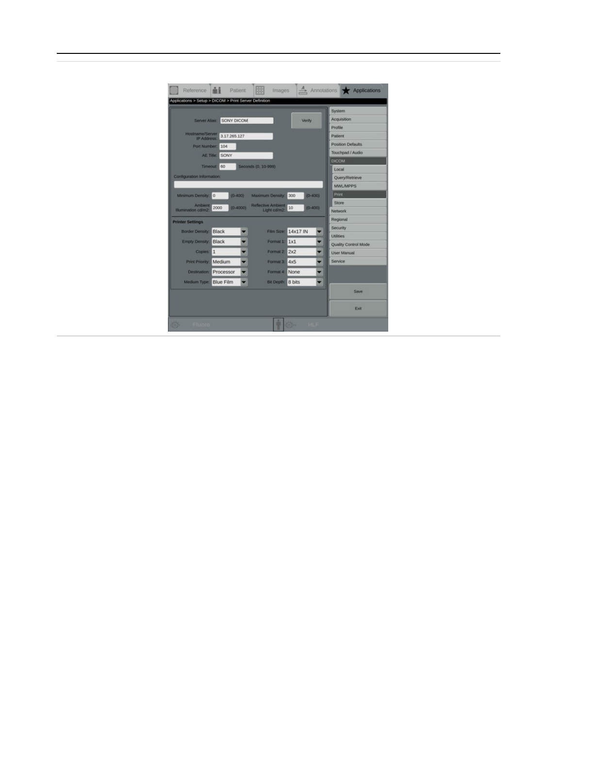
2 System setup
Figure 2-29: Print Server Definition screen
Obtain the following information from the facility's network administrator or from the device's
DICOM Conformance Statement and enter it in on this screen:
Print Server Configuration
Server Alias
Enter the unique name, internal to the system, used to identify the server in the list of avail-
able destination devices.
Hostname / Server IP Address
Enter the unique host name or IP address assigned to the configured server.
Port Number
Enter the port number assigned to the server running on the system. The default value is
104. Valid values are 1-65535.
AE Title
Enter the DICOM Application Entity Title. AE Titles are limited to a maximum of 16 char-
acters, and are case-sensitive. This title is used for queries. The title also is used by the
Retrieve Server in response to store requests.
Timeout
Select a limit to set the time, from 10 to 999 seconds, that the system waits for a response
from the server before timing out, or select 0 to allow the system to try to reconnect to a
server indefinitely.
2-32
Page 75

2 System setup
Configuration Information
See the DICOM Conformance statement for configuration information options.
Minimum Density
Select a minimum print density, from 0-400. See the DICOM Conformance Statement for the
device.
Maximum Density
Select a maximum print density, from 0-400. See the DICOM Conformance Statement for
the device.
Ambient Illumination cd/m2
Select the appropriate ambient illumination, from 0-4000.
Reflective Ambient Light cd/m2
Select the appropriate reflective ambient light, from 0-400.
Printer Settings
Border Density
Select the appropriate image border density, Black or White.
Empty Density
Select the appropriate image empty density, Black or White.
Copies
Enter the default number of copies printed each time a print command is sent to the
printer, from 1-10. This can be overridden at the time of printing.
Print Priority
Select the priority of the print jobs, High, Medium, or Low.
Destination
Select the print destination, Magazine or Processor.
Medium Type
Select the print medium, Paper, Clear Film, or Blue Film.
Film Size
Select the film size:
l
8 x 10
l
10 x 12
l
10 x 14
l
11 x 14
l
14 x 14
l
14 x 17
l
24 x 30
2-33
Page 76
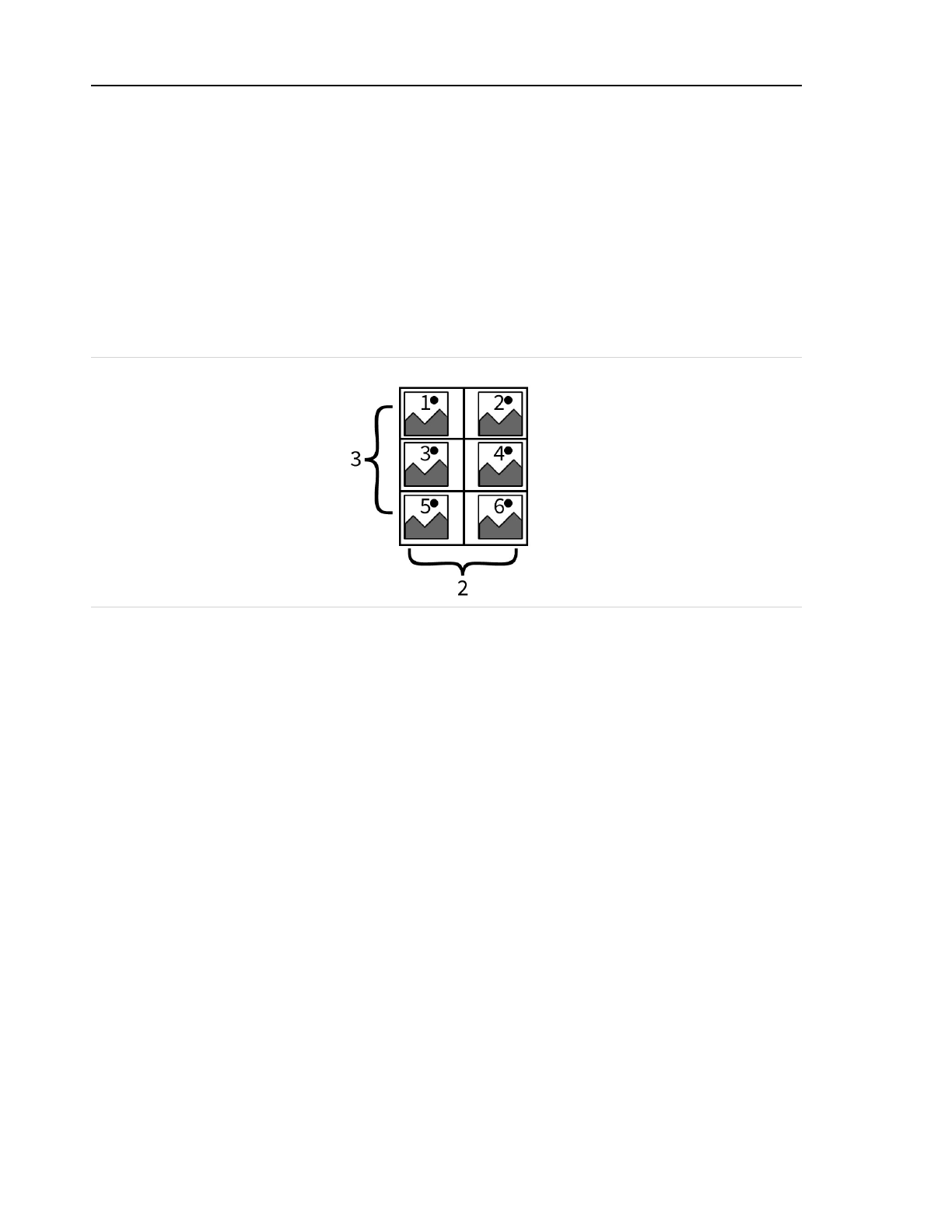
2 System setup
Format 1-4
Select the format for the print output for the X-rays.
The format definition determines the printed format for the X-ray images in columns and
rows. The format choices are limited to those available from the selected printer. The total
number of images printed on one film sheet is the product of the two numbers. For
example, 2 columns multiplied by 3 rows, equals a total of six images printed on one film.
The system supports the following formats (columns x rows):
1 x 1 2 x 2 3 x 3 4 x 4
1 x 2 2 x 3 3 x 4 4 x 5
Figure 2-30: Example of a 2 x 3 print layout
Bit Depth
Select a bit depth, 8 bits or 12 bits.
Verify
Touch to test that the settings are correct. If the system is connected, a DICOM SERVER
VERIFIED SUCCESSFULLY message displays. Touch OK and follow the message instruc-
tions.
Otherwise, a VERIFY FAILED message displays. Touch OK to continue and then check the
settings entered. If the settings are correct but the verification fails, contact the facility's
Network Administrator.
Touch Save to save the settings. If no changes have been made, the Save button is unavailable.
Touch Exit to return to the main Applications screen without saving any changes; a SAVE
CHANGES BEFORE EXITING? message displays. Follow the message instructions.
Set up DICOM query / retrieve server
Use the Query / Retrieve Server Definition screen to set up a server for retrieving patient images
from a DICOM server.
See 8.3.2 Retrieve previous exams for the current patient from a DICOM Query / Query Retrieve server
(page 8-17) for details on retrieving images from a DICOM Query / Retrieve server.
2-34
Page 77
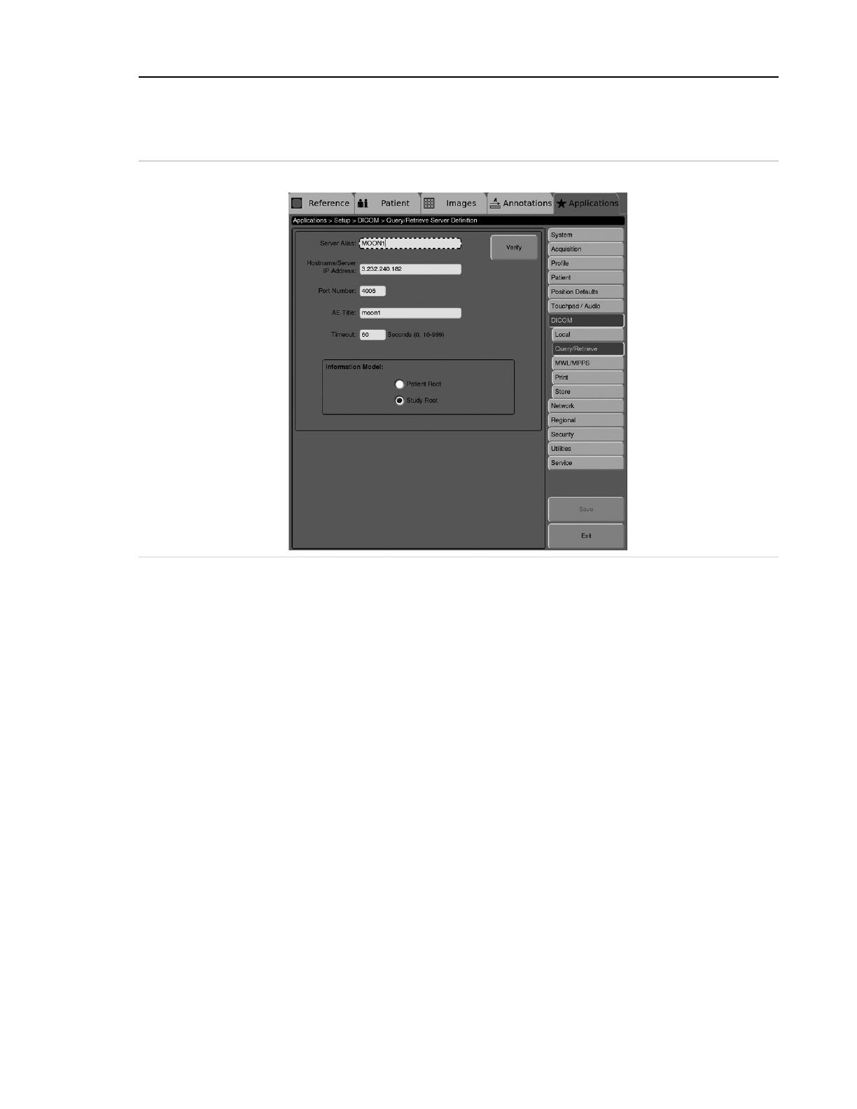
2 System setup
On the DICOM screen, select Query / Retrieve Server from the Server Type menu, and touch
Add..., or touch the Query / Retrieve button in the right-hand menu. A screen similar to the
following displays.
Figure 2-31: Query / Retrieve Server Definition screen
Obtain the following information from the facility's network administrator or from the device's
DICOM Conformance Statement and enter it in on this screen:
Server Information
Server Alias
Enter the unique name, internal to the system, used to identify the server in the list of avail-
able destination devices.
Hostname / Server IP Address
Enter the unique host name or IP address assigned to the configured server.
Port Number
Enter the port number assigned to the server running on the system. The default value is
104. Valid values are 1-65535.
AE Title
Enter the DICOM Application Entity Title. AE Titles are limited to a maximum of 16 char-
acters, and are case-sensitive. This title is used for queries. The title also is used by the
Retrieve Server in response to store requests.
2-35
Page 78

2 System setup
Timeout
Select a limit to set the time, from 10 to 999 seconds, that the system waits for a response
from the server before timing out, or select 0 to allow the system to try to reconnect to a
server indefinitely.
Information Model
Select the appropriate information model for the server that is being configured. For the
appropriate information model see the AACS Admin or to the DICOM conformance state-
ment for the server. Select a model that has both find and move support. Find and move
support are necessary for the Query/Retrieve application to function properly.
Patient Root - start queries at the patient level, then the series level.
Study Root - start queries at the study level, then the series level.
Verify
Touch to test that the settings are correct. If the system is connected, a DICOM SERVER
VERIFIED SUCCESSFULLY message displays. Touch OK and follow the message instruc-
tions.
Otherwise, a VERIFY FAILED message displays. Touch OK to continue and then check the
settings entered. If the settings are correct but the verification fails, contact the facility's
Network Administrator.
Touch Save to save the settings. If no changes have been made, the Save button is unavailable.
Touch Exit to return to the main Applications screen without saving any changes; a SAVE
CHANGES BEFORE EXITING? message displays. Follow the message instructions.
Store / Storage Commit Server
Use the Store / Storage Commit Server Definition screen to set up a DICOM store server, a
networked computer used to archive and transfer DICOM images and other related digital data
between DICOM nodes, allowing exchange of data among multiple devices over a DICOM network.
On the DICOM screen, select Store / Store Commit from the Server Type menu, and touch Add...,
or touch the Store button in the right-hand menu. A screen similar to the following displays.
2-36
Page 79
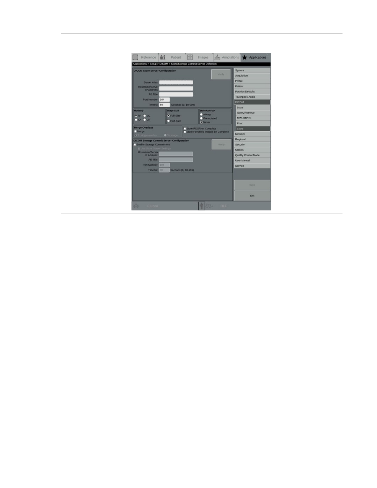
2 System setup
Figure 2-32: Store / Storage Commit Server Definition screen
Obtain the following information from the facility's network administrator or from the device's
DICOM Conformance Statement for each DICOM storage server on the network:
DICOM Store Server Configuration
Server Alias
Enter the unique name, internal to the system, used to identify the server in the list of avail-
able destination devices.
Hostname / Server IP Address
Enter the unique host name or IP address assigned to the configured server.
AE Title
Enter the DICOM Application Entity Title. AE Titles are limited to a maximum of 16 char-
acters, and are case-sensitive. This title is used for queries. The title also is used by the
Retrieve Server in response to store requests.
Port Number
Enter the port number assigned to the server running on the system. The default value is
104. Valid values are 1-65535.
Timeout
Select the maximum length of time to allow for verification. Select 0 for no maximum time,
or select from 10 to 999 seconds.
2-37
Page 80

2 System setup
Verify
Touch to test that the settings are correct. If the system is connected, a DICOM SERVER
VERIFIED SUCCESSFULLY message displays. Touch OK and follow the message instruc-
tions.
Otherwise, a VERIFY FAILED message displays. Touch OK to continue and then check the
settings entered. If the settings are correct but the verification fails, contact the facility's
Network Administrator.
Modality
Select the image modality supported by the storage device. The system supports the fol-
lowing modalities:
RF - X-ray Radio Fluoroscopic Image Storage - static and cine.
XA - X-ray Angiographic Image Storage - static and cine.
SC - Secondary Capture Image Storage - 1K x 1K static image only. Multi-SC is supported,
but cannot store overlays.
CR - Computed Radiography image storage. CR images are single-frame screen capture type
image with annotation and markers.
Image Size
Select the image size supported by the storage device, either Full size or Half size.
Store Overlay
Select the appropriate image overlay setting for storage of overlay information associated
with an image as data separate from the image. The Multi-SC image modality does not
allow stored overlays.
See Table 2-1: Image overlay behavior (page 2-39) below explains the Store Overlay and
Merge Overlays behavior in detail.
Always - Always store overlay information with the image. With this setting, additional data
elements are sent with every image, whether or not the user added any post-processed
Markers or Comments to the image.
If Annotated - Store overlay information only if the image is annotated. With this setting,
two additional data elements are sent in addition to the image data if the user adds any
post-processing markers or comments to the image. The first image data element contains
the clinical image, the second contains markers, comments, arrows and the measurement
results, and the third contains all the information in the periphery of the image, such as
patient demographics, X-ray technique, window and level settings, and institute name,
date, and time.
Never - Never store overlay information with the image. With this setting, no additional
information or data elements is sent. This optimizes network transfer speed, but any mark-
ers or comments added to the image are not sent with the image.
2-38
Page 81
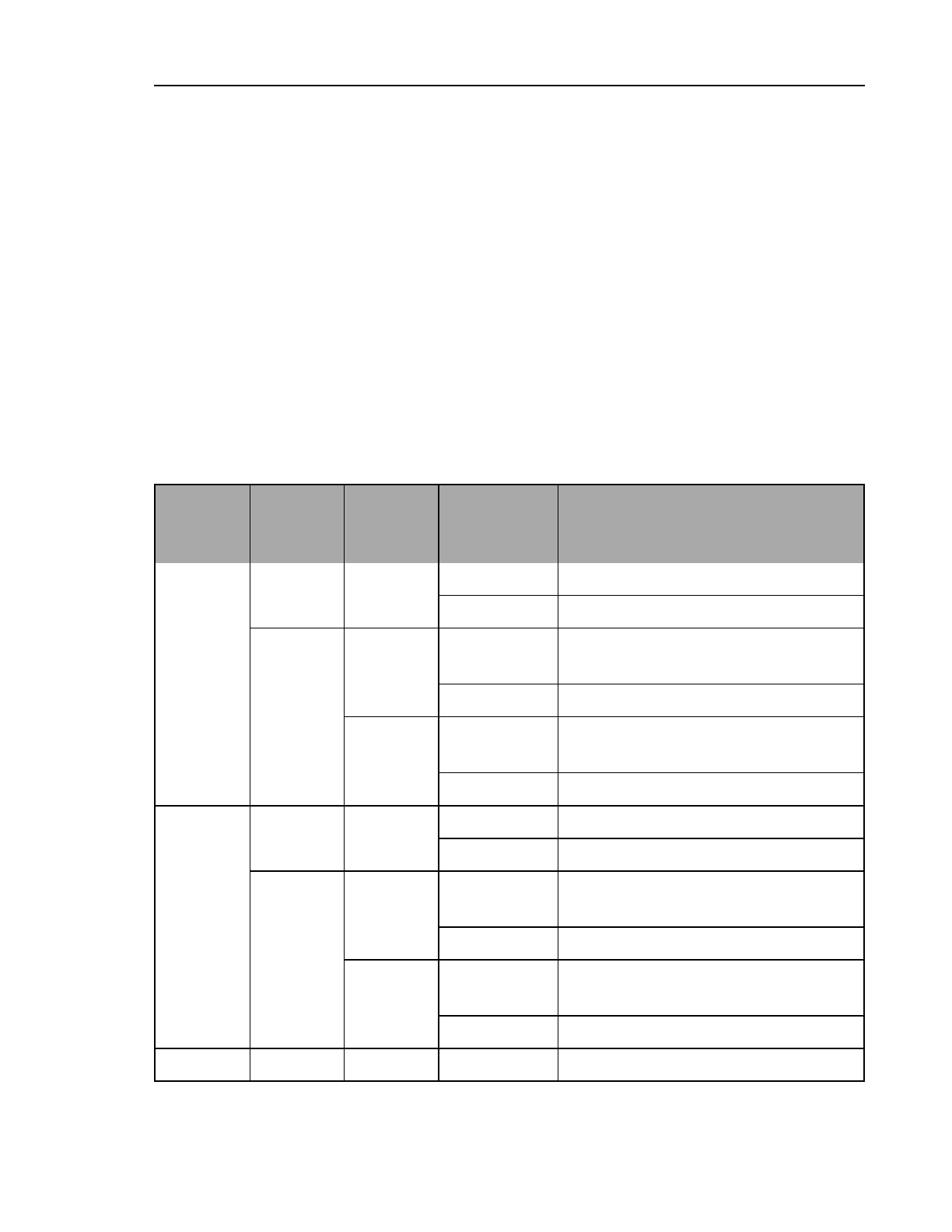
2 System setup
Merge Overlays
Select the check box to have annotation and patient information combined into a single
overlay and then stored with the image, or clear the check box to store the information sep-
arately.
Merge - Selecting this check box merges the overlay and image. Select one of the following
options:
l
To single overlay - Annotations, text, and image information overlays are
stored together in a single overlay. The Multi-SC image modality does not allow
overlays.
l
To image - Annotations, text, and image information become part of the
clinical image and cannot be removed. The Multi-SC image modality does not
allow merged overlays.
Image overlay behavior varies depending on the Store Overlay and Merge Overlay settings.
Table 2-1: Image overlay behavior
Store
Overlay
Setting
Merge
Overlay
Setting
Merge
Overlay
Option
Image
has
annotations?
Resulting
overlays
produced
Always
No n/a
Yes 2: image information, annotations
No 1: image information
Yes
Image
Yes
0: image information and annotations
burned to image
No 0: image information burned to image
Single Over-
lay
Yes
1: image information and annotations
combined
No 1: image information
If Annot-
ated
No n/a
Yes 2: image information, annotations
No 0
Yes
Image
Yes
0: image information and annotations
burned to image
No 0
Single Over-
lay
Yes
1: image information and annotations
combined
No 0
Never n/a n/a n/a 0: nothing burned to image
2-39
Page 82

2 System setup
Store RDSR on Complete
Select this check box to store the Radiation Dose Structured Report (RDSR) upon the com-
pletion of the exam. This server shows up in the list of default RDSR server configurations
that can be selected to always store RDSRs. This applies only if the server is the Default
RDSR server.
Store Favorited Images on Complete
Select this check box to store images marked as Favorites upon the completion of the
exam. This setting only applies if the Default Store Server set up on the DICOM screen is
selected. See Default Store Server (page 2-27).
DICOM Storage Commit Server Configuration
Enable Storage Commitment
Select to enable storage commitment on a DICOM store server. DICOM Storage Com-
mitment provides advanced safekeeping of DICOM images and data that have been shared
across a DICOM network.
Use Store Server Settings
Select to use the same information as used for the store server, if the IP address, port num-
ber, and other settings are all the same. Clear this check box to manually enter different set-
tings.
Hostname / Server IP Address
Enter the unique host name or IP address assigned to the configured server.
AE Title
Enter the DICOM Application Entity Title. AE Titles are limited to a maximum of 16 char-
acters, and are case-sensitive. This title is used for queries. The title also is used by the
Retrieve Server in response to store requests.
Port Number
Enter the port number assigned to the server running on the system. The default value is
104. Valid values are 1-65535.
Timeout
Select the maximum length of time to allow for verification. Select 0 for no maximum time,
or select from 10 to 999 seconds.
Verify
Touch to test that the settings are correct. If the system is connected, a DICOM SERVER
VERIFIED SUCCESSFULLY message displays. Touch OK and follow the message instruc-
tions.
Otherwise, a VERIFY FAILED message displays. Touch OK to continue and then check the
settings entered. If the settings are correct but the verification fails, contact the facility's
2-40
Page 83
2 System setup
Network Administrator.
Touch Save to save the settings. If no changes have been made, the Save button is unavailable.
Touch Exit to return to the main Applications screen without saving any changes; a SAVE
CHANGES BEFORE EXITING? message displays. Follow the message instructions.
Troubleshoot DICOM setup
If the system experiences an error trying to connect to a DICOM server, a CANNOT CONNECT TO
DICOM SERVER message displays.
Touch Verify to confirm that the target server is online, and that its IP address, port number, and
AE title are configured properly on the system. If the message persists, call for service.
Additional DICOM messages might display if there is a problem with DICOM functionality:
l
DICOM ERROR Check the Transfer Status Screen on the system for detailed error
information. Follow the instructions in the Transfer Status Screen to resolve the
issue, or call for service. See page 11-33 for more information on this message.
l
DICOM MOVE DESTINATION UNKNOWN Make sure that PACS is configured to allow
images to be retrieved. See page 11-34 for more information on this message.
l
DICOM SERVER OUT OF RESOURCES, TRY AGAIN LATER This is probably a temporary
condition caused by currently high usage of the server. If this message persists, call
for service. See page 11-34 for more information on this message.
l
DICOM SERVER RESPONSE MISSING REQUIRED DICOM TAGS See the DICOM Log for
more information or call for service.See page 11-34 for more information on this
message.
2.2.1.8 Set up network configuration
Some system setup is limited to Administrative users only. Emergency and clinical users
do not have access to the screens and functions described in this section.
When the system is connected to a network, a network status icon displays in the status bar on
left side of the screen.
2-41
Page 84
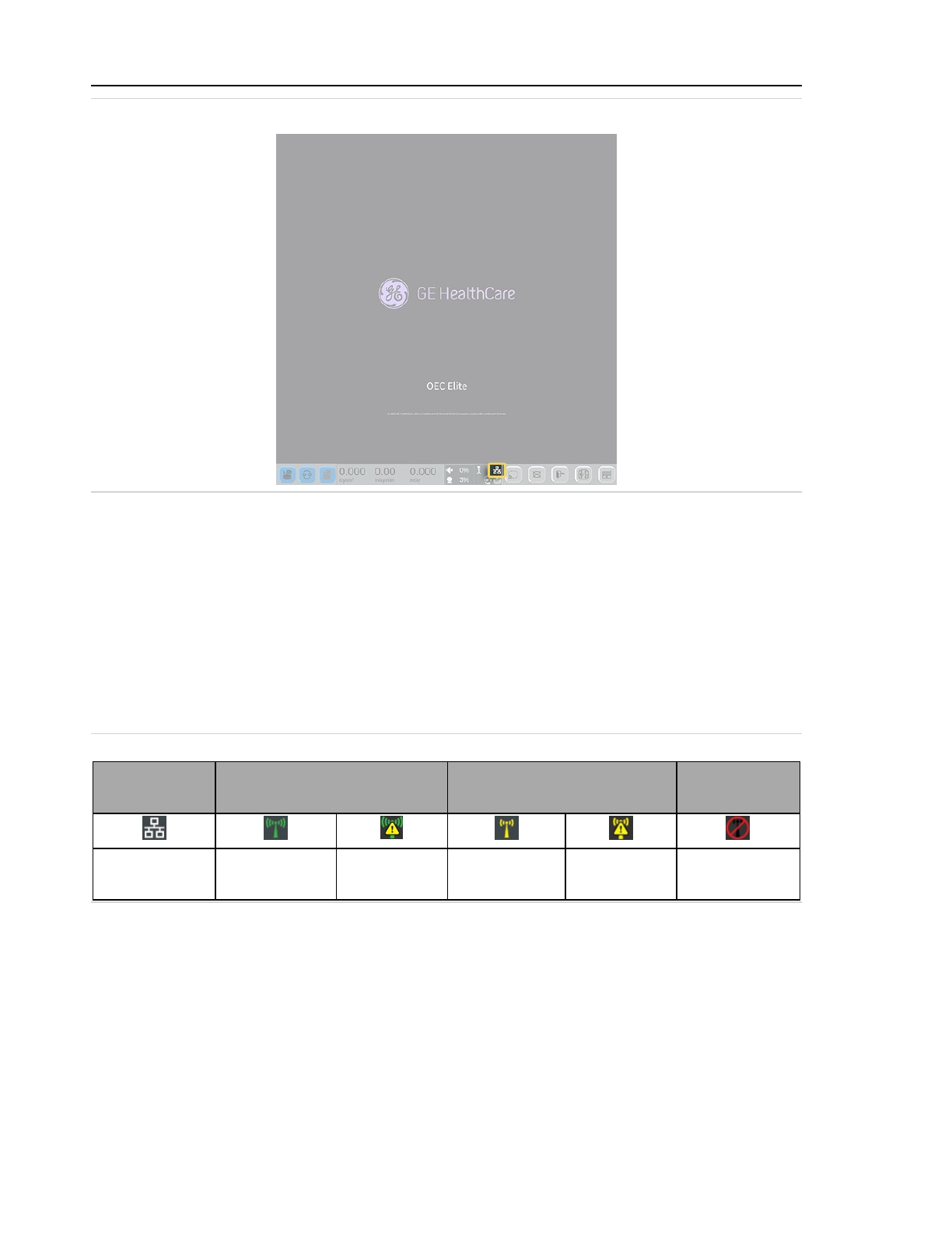
2 System setup
Figure 2-33: Network status icon
The network status icon varies to indicate the type of network and its connectivity or status.
l
An Ethernet icon indicates that the system is connected to a wired network.
l
A green wireless icon indicates a strong wireless connection.
l
A yellow wireless icon indicates a weak wireless connection.
l
A wireless icon with a yellow warning triangle indicates that all the configured settings to
connect to the network are correct, but the system is waiting for an assigned IP address
from the network before it can perform any network related actions. This may happen if the
network that the system is connecting to is slow or unresponsive.
l
A red circle with a strike-though icon indicates that there is no network connection.
Figure 2-34: Network status icons
Wired
network
Strong wireless
network
Weak wireless
network
No
network
Connected
to network
Connected
to network
No IP
address
Connected
to network
No IP
address
Not
connected
Network Configuration
Touch Network in the menu to display the Network Configuration screen. This screen dis-
plays the current network configuration details and provides a field to enter or edit a Host
Name.
If setting or editing the Host Name, touch Save, confirm the changes in the message, and
then touch Exit to return to the main Applications screen.
2-42
Page 85
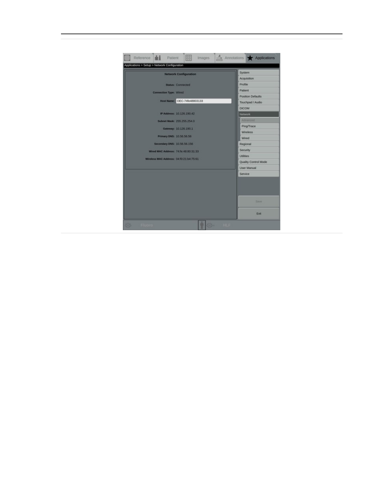
2 System setup
Figure 2-35: Network Configuration screen with a wired connection
The configuration details are defined in the following list:
Status
Displays whether the network connection status: Connected or Disconnected.
Connection Type
Displays the type of the current connection: Wired or Wireless.
Host Name
Displays the name of the host network, if applicable. Provide a name if this field is blank.
Network Name SSID
Displays the wireless network name or Service Set Identifier (SSID) for hidden networks.
This field is hidden when the system is connected to a wired network.
IP Address
Displays the host Internet Protocol (IP) address.
Subnet Mask
Displays the Subnet Mask address.
Gateway
Displays the Gateway address.
2-43
Page 86
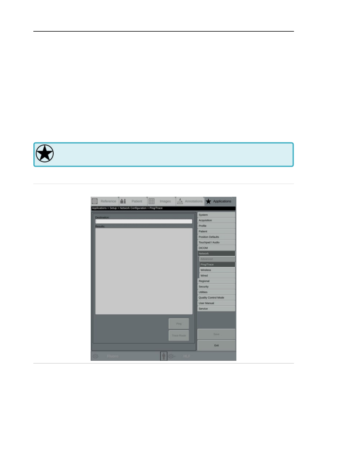
2 System setup
Primary DNS
Displays the primary Domain Name Server (DNS).
Secondary DNS
Displays the secondary Domain Name Server (DNS), if supplied.
Wired MAC Address
Displays the media access control (MAC) address of the wired network adapter.
Wireless MAC Address
Displays the media access control (MAC) address of the wireless network adapter.
Ping / Trace
Some system setup is limited to Administrative users only. Emergency and clinical users
do not have access to the screens and functions described in this section.
Touch Ping / Trace... or touch Ping / Trace in the menu to display the Ping / Trace screen.
Figure 2-36: Ping/Trace screen
Destination
Enter a network destination, an IP address or server name.
2-44
Page 87

2 System setup
Results
Results of the network ping or trace route display in this text box.
Ping
Touch this button to test the network connection. See Test the network connection (page 2-
45) for how to use the ping function.
Trace Route
Touch this button to display the network route between the system and the destination net-
work. See Trace the network connection route (page 2-45) for how to use trace route func-
tion.
Test the network connection
1. Enter a network destination, an IP address or server name, in the Destination box.
2. Touch Ping. The system sends a command to the destination to test whether the server is
connected and available. The results of the ping display in the results window.
3. If the network test is successful, the network connection is working correctly.
4. If the network test is unsuccessful, check the destination and try again.
If the network test is still unsuccessful, consult with the local network administrator and
check the system's network configuration and the network cable to make sure that they are
set up correctly.
Finally, contact GE HealthCare Customer Service for help.
Once the network is working properly, touch Exit or Network in the menu to return to the
Network Configuration screen.
Trace the network connection route
1. Enter a network destination, an IP address or server name, in the Destination box.
2. Touch Trace Route. The system sends a command to the destination.
3. If the network test is successful, the route the command followed displays in the results
window.
4. If the network test is not successful, check the destination and try again.
If the network test is not successful, consult with the local network administrator and check
the system's network configuration and the network cable to make sure that they are set
up correctly.
Finally, contact GE HealthCare Customer Service for help.
Once the network is working properly, touch Exit or Network in the menu to return to the
Network Configuration screen.
2-45
Page 88
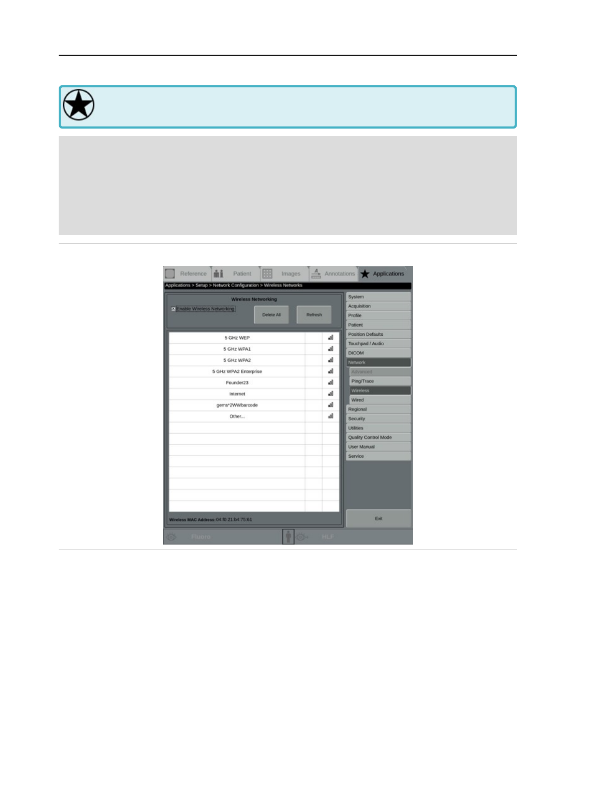
2 System setup
Set up wireless networks
Some system setup is limited to Administrative users only. Emergency and clinical users
do not have access to the screens and functions described in this section.
Note: On slow wireless networks, the system can sometimes experience a delay during the login
process. One or more of the following measures can improve connection times:
l
Connect to a wired network.
l
Connect to a faster wireless network.
l
Disconnect from the network entirely.
Figure 2-37: Wireless Networks screen
Wireless Networking
Enable Wireless Networking
Select this check box to detect and access existing wireless networks, or clear it to disable
the wireless radio.
Refresh
Touch this to scan for currently available wireless networks.
Delete All
2-46
Page 89
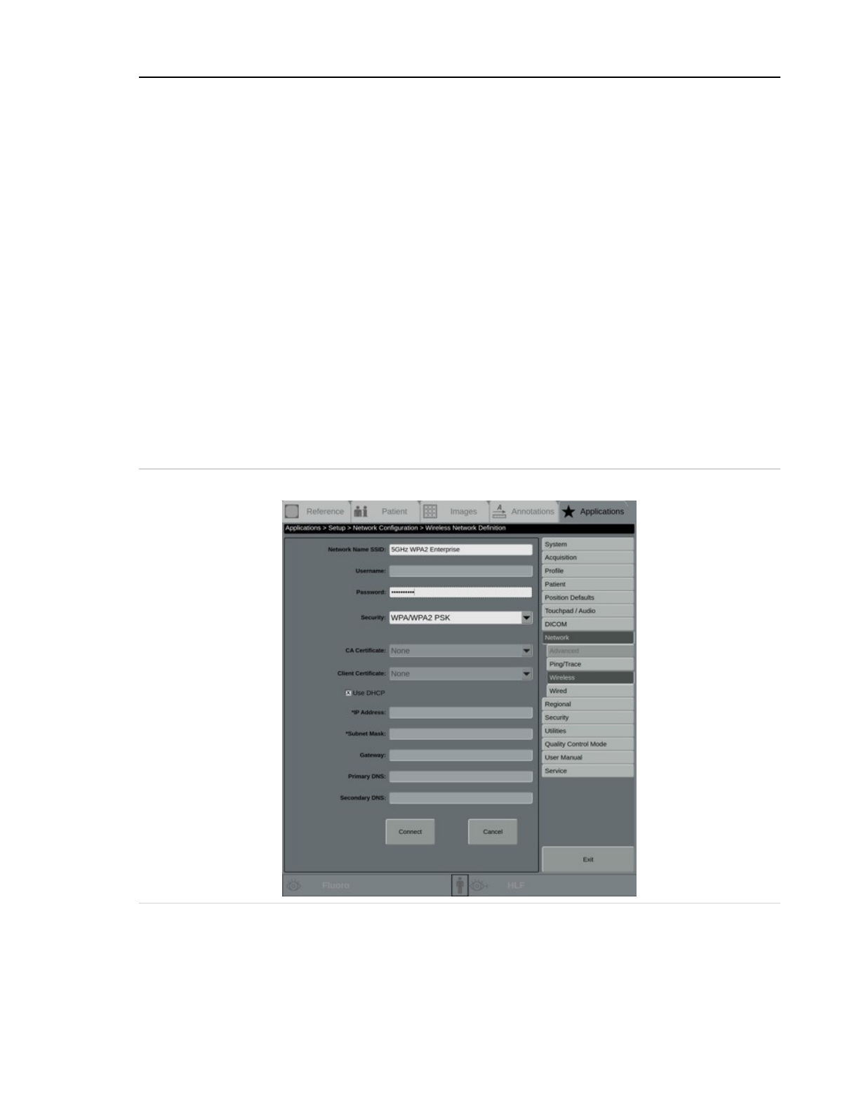
2 System setup
Touch this to delete all saved wireless network information on the system, including impor-
ted certificates for those networks.
This screen lists detected wireless networks. The name of the detected wireless networks are
listed in the first column. The signal strength is listed in the second column and the signal quality
is listed in the third column.
Connection column
This column displays an icon next to the connected network, if applicable.
Signal Quality column
This column displays icons indicating the wireless network's signal strength.
Touch Exit to return to the Network Configuration screen.
Edit or add wireless networks
Use the Wireless Network Definition screen to edit existing networks or add a new network.
Touch the name of the network to edit network details, or touch Other... to add a wireless
network with a hidden SSID.
Figure 2-38: Wireless Network Definition screen
The Wireless Network Definition screen displays the following:
2-47
Page 90

2 System setup
Network Name SSID
Displays the selected network's name or Service Set Identifier (SSID). If the selected net-
work is a hidden network, this field is editable.
Username
Enter the username for an account on the wireless network. This is only configurable if
Security type is WPA/WPA2 EAP.
Password
Enter the wireless network or client certificate private key password.
Security
The detected authentication protocol of the selected network is automatically populated in
this field.
If the selected network is hidden, select the type of security used by the network. Choose
WEP, WPA/WPA2 PSK,or WPA/WPA2 EAP.
When FIPS140 Enforcing is enabled, networks with an unsupported security type is not
selectable. If you attempt to connect to a network with a security type or encryption which
is not supported by FIPS140-3, a message displays and you are prompted to select another
network.
Networks supported under FIPS140-3 are WPA2 PSK CCMP networks and WPA2 EAP TLS
CCMP networks. Networks using WPA, WEP, or TKIP encryption are not supported by
FIPS140-3. Use WPA/WPA2 EAP or WPA/WPA2 PSK when FIPS140-3 Enforcing is enabled.
EAP Type
If the selected network uses WPA/WPA2 EAP, select the type of Extensible Authentication
Protocol (EAP) used. Choose Automatic, PEAP-MSCHAPV2, PEAP-MD5, PEAP-GTC, TTLS-
MSCHAPV2, TTLS-MD5, or TLS. By default, the system uses Automatic and cycles through
all options to find correct type.
If FIPS140 Enforcing is enabled, this field is not configurable, and only TLS is supported.
CA Certificate
Select CA Certificate.
Client Certificate
Select Client Certificate.
Load Certificates
If the selected network uses WPA/WPA2 EAP, touch this to manage certificates for the net-
work.
2-48
Page 91
2 System setup
Use DHCP
Select to allow the system to use Dynamic Host Configuration Protocol (DHCP) to auto-
matically obtain an IP address and other necessary network information from a server on
the network.
If the network does not have a DHCP server, enter the information on this screen manually.
IP Address
Enter the host Internet Protocol (IP) address.
Subnet Mask
Enter the Subnet Mask address.
Gateway
Enter the Gateway address. This is optional.
Primary DNS
Enter the primary Domain Name Server (DNS). This is optional.
Secondary DNS
Enter the secondary Domain Name Server (DNS). This is optional.
Forget
This is displayed when the system has previously attempted to connect to a network. Touch
to delete the saved data associated with the network and return to the Wireless Network
Definition screen.
Connect
Touch to connect to the wireless network.
Cancel
Touch to return to the Network Configuration screen without saving any changes.
Touch Exit to return to the Network Configuration screen.
Manage certificates
Use the Certificate management screen to import and delete certificate files on systems using
EAP authentication. See Certificate management (page 2-70)
Set up wired networks
Some system setup is limited to Administrative users only. Emergency and clinical users
do not have access to the screens and functions described in this section.
Touch Wired in the menu to display the Wired Network screen.
2-49
Page 92
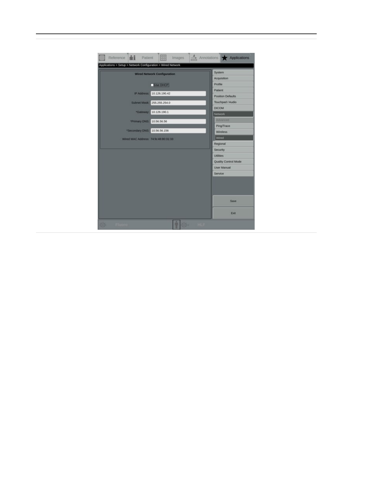
2 System setup
Figure 2-39: Wired Network screen
The Wired Network screen displays the following:
Wired Network Configuration
Use DHCP
Select this check box to allow the system to use Dynamic Host Configuration Protocol
(DHCP) to automatically obtain an IP address and other necessary network information
from a server on the network.
If the network does not have a DHCP server, enter the information on this screen manually.
IP Address
Enter the host Internet Protocol (IP) address.
Subnet Mask
Enter the Subnet Mask address.
Gateway
Enter the Gateway address.
Primary DNS
Enter the primary Domain Name Server (DNS).
Secondary DNS
Enter the secondary Domain Name Server (DNS). This is optional.
2-50
Page 93

2 System setup
Wired MAC Address
This displays the media access control (MAC) address of the wired network adapter.
Touch Save, confirm the changes in the message, and then touch Exit to return to the Network
Configurations screen.
2.2.1.9 Set up regional settings
Some system setup is limited to Administrative users only. Emergency and clinical users
do not have access to the screens and functions described in this section.
Use the Regional Settings screen to set the hospital name, select decimal, radiation, and DAP unit
defaults, and set up the system time and date.
Touch Regional in the menu to display the Regional Settings setup screen.
Figure 2-40: Regional Settings setup screen
Hospital Name
The full or user-designated name of the hospital. This value displays on the image overlay.
Decimal Format
Select the preferred regional format, either 1,000.00 or 1.000,00.
Radiation Units
Select the preferred regional format, either gray (mGy, Gy) or roentgen (R).
2-51
Page 94

2 System setup
DAP Units
Select the preferred format for Dose Area Product (DAP). If the selected radiation unit is
gray, choose from Gy cm
2
, cGy cm
2
, mGy m
2
, or mGy cm
2
. If the selected radiation unit is
roentgen, the default Rcm
2
is selected.
Date/Time Settings
X-Ray Timer Units
Select the preferred regional format, either mm.d or mm:ss.d.
Set Automatically
Select to set the time and date automatically, using the local network. If this is selected,
choose one of the following:
l
Use DHCP to request IP addresses and networking parameters automatically from a
DHCP server.
l
Enter NTP Address and then enter a valid IP address to manually identify the address
to synchronize all participating computers. If this setting is selected, it must be
verified using the Verify button to take effect.
Verify
Touch to check automatic time and date settings.
Note: The system forces a restart for certain system changes to take effect, which can delay care.
Do not change settings during an exam.
Changes that will trigger a restart include Regional Date and Time settings, Set Up Login,
FIPS, Legacy Security Mode, and Portable Media.
Depending on network conditions, verification might take longer than the expected 3-5
seconds or might fail, and startup time might be longer than expected. Contact the local
network administrator for assistance with NTP settings.
If the system is configured to set the date and time automatically, always touch Verify after
changing the UTC time zone offset prior to saving. The offset selection is not saved if it is
not verified.
Set Manually
Select to enter a complete timer and date manually, if there is no local network.
Timezone Offset
Select the appropriate UTC (Coordinated Universal Time) time offset. Select the offsets
hour, half an hour, or fifteen minute increments. By default, the system uses -05:00, which
is Eastern Time.
2-52
Page 95
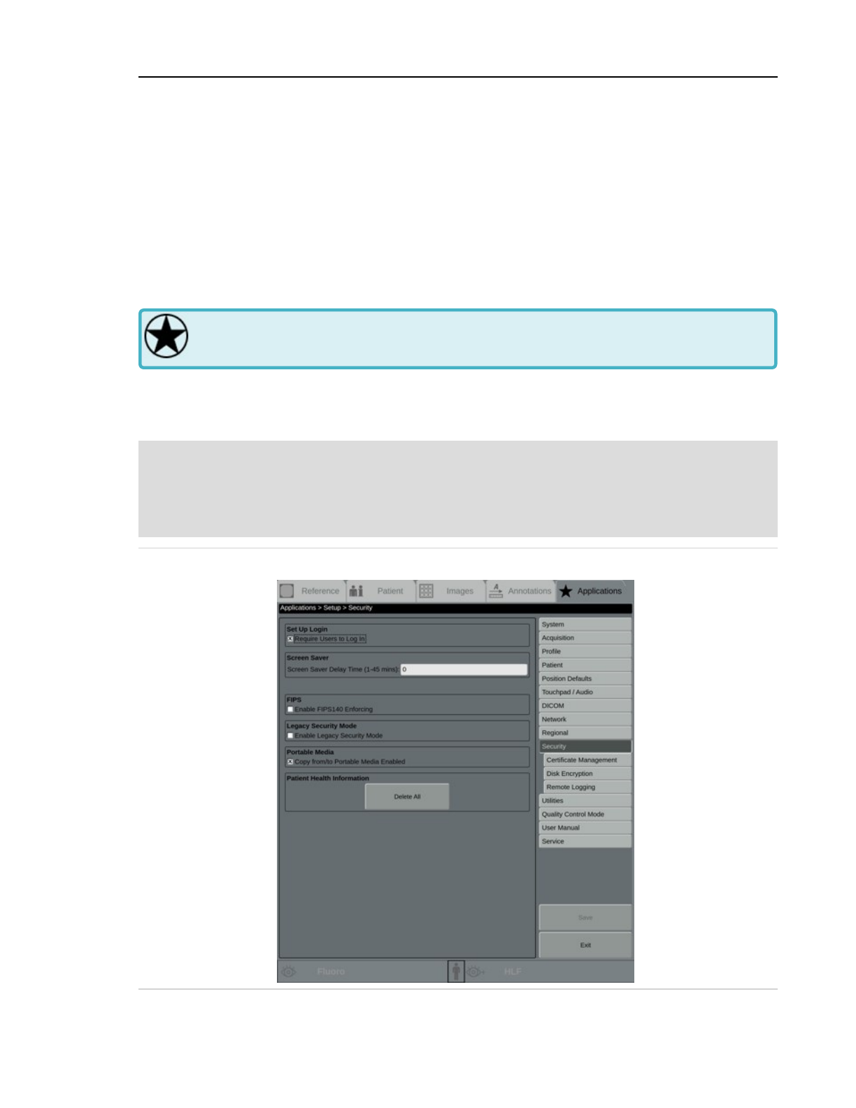
2 System setup
Daylight Savings
Select if the local region uses Daylight Savings Time. This setting must be manually cleared
during Standard time.
Date Format
Select the preferred regional format, either MM/DD/YYYY, DD.MM.YYYY, or YYYY/MM/DD.
Touch Save to save the settings or touch Exit to return to the main Applications screen. If settings
have been changed but not saved, a message displays. Follow the message instructions.
2.2.1.10 Set up security
Some system setup is limited to Administrative users only. Emergency and clinical users
do not have access to the screens and functions described in this section.
Use the Security screen set up security features.
Touch Security in the menu to display the Security setup screen.
Note: The system forces a restart for certain system changes to take effect, which can delay care.
Do not change settings during an exam.
Changes that will trigger a restart include Regional Date and Time settings, Set Up Login,
FIPS, Legacy Security Mode, and Portable Media.
Figure 2-41: Security setup screen
2-53
Page 96

2 System setup
Set Up Login
Require Users to Log In
Select this check box to require a password after the system has been started up or locked,
or clear the check box to allow system use without a password.
If users are required to log in, an Emergency User button displays on the Login screen.
Emergency users do not have to enter a password and only have access to basic emergency
functionality such as creating exams and taking images.
If users are not required to log in to use the system, all users have Clinical user access to
the system. Any access to Administrative user functionality is restricted on systems in this
case. The exception is that the Require Users to Log In check box remains available.
If Administrative user level changes need to be made on a system that does not require
users to log in, select the Require Users to Log In check box and then restart the system. An
Administrative user can then log in and make security changes to the system.
If desired, clear then Require Users to Log In check box once changes are complete. When
the system is restarted, it will not require a password and all users once again have Clinical
user access.
Screen Saver
Screen Saver Delay Time (1 - 45 mins)
The screen saver dims the screen when the system is not in use, and is designed to reduce
wear and monitor burn-in on the system to increase the life of the monitor. It does not log
out or lock the system, and a password is not required to return the screen to full bright-
ness.
Enter the number of minutes until the system dims the screen. Select 0 to disable the fea-
ture or select from 1 to 45 minutes. By default, the system waits 10 minutes.
Touch the screen or press any key on the keyboard, any control panel key, any Workstation
keypad key, or any X-ray switch to return the screen to full brightness. Note that pressing
an X-ray switch also initiates an X-ray shot.
Notification
Notification Email Addresses
Enter email addresses to receive OS level audit log failures.
SMTP Server Address
Enter the mail server address for the email address entered above.
Banner Upload
Banner File
Select a banner to display.
To set up a banner:
2-54
Page 97

2 System setup
1. Create a plain text (.txt) file containing the desired banner text on a computer or
laptop.
2. Save the text file to the root directory to a non-powered USB drive.
3. Insert the USB drive into a USB port on the system.
4. On the Security screen, touch the Banner File menu and select the text file from the
list
5. Touch Save and then touch Exit.
FIPS
Enable FIPS140 Enforcing
Select to enforce Federal Information Processing Standard Publication 140, a U.S. gov-
ernment encryption security standard.
Networks supported under FIPS140-3 are WPA2 PSK CCMP networks and WPA2 EAP TLS
CCMP networks. Networks using WPA, WEP, or TKIP encryption are not supported by
FIPS140-3.
When FIPS140-3 enforcing is enabled, networks with an unsupported security type is not
selectable. If you attempt to connect to a network with a security type or encryption which
is not supported by FIPS140-3, a message displays and you are prompted to select another
network.
If a certificate imported on the Certificates screen does not require a password, clear
Enable FIPS140 Enforcing to connect to the network.
Portable Media
Copy from/to Portable Media Enabled
Select to allow images and data to be copied from the system to portable media devices
such as USB devices or burned to DVDs. Select to allow images and data to be copied from
the system to portable media devices such as USB devices. Clear to prevent images and
data from being copied.
Patient Health Information
Delete All
Touch to delete all patient information and data, including exams and contents of the
Patient screen, before shipping a system or having it serviced. A confirmation message dis-
plays. Follow the message instructions.
Touch Save to save the settings or touch Exit to return to the main Applications screen. If settings
have been changed but not saved, a message displays. Follow the message instructions.
Antivirus
Touch Antivirus in the menu to display the McAfee Endpoint Security for Linux Threat Prevention
screen.
The screen displays an Entering Antivirus Mode message. Note that the system must be
restarted after exiting the antivirus software and resuming imaging.
2-55
Page 98
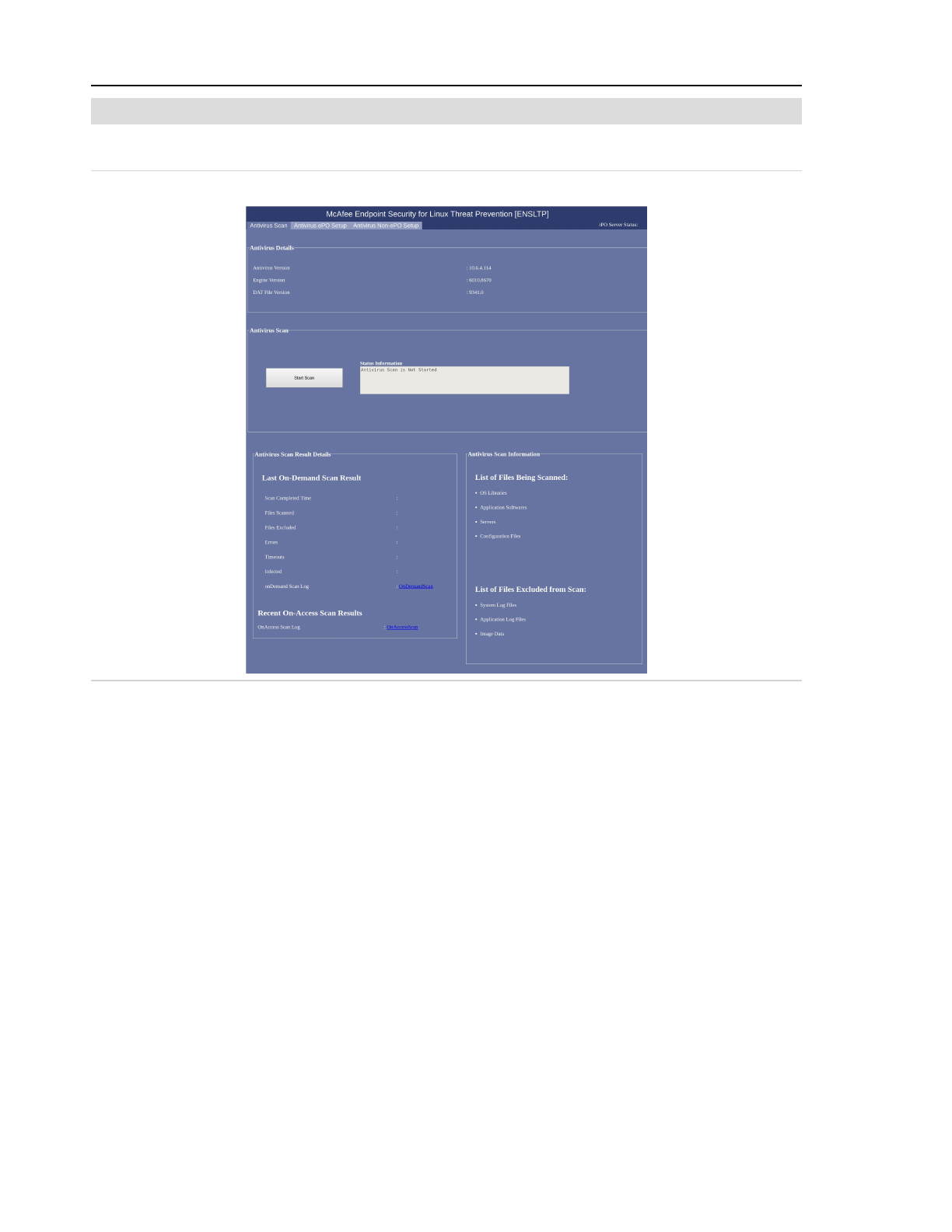
2 System setup
Note: Do not perform McAfee agent updates from the ePO server.
Touch the Antivirus Scan tab to display the Antivirus Scan screen.
Figure 2-42: Antivirus Scan screen
Antivirus Details
Shows the latest versions of the antivirus software, antivirus engine, and DAT file.
Antivirus Scan
Start Scan
Touch to begin an OnDemand (manual) scan.
Status Information
Shows status of the antivirus software. Options include Not Started, Starting, Running,
Stopping, and Stopped.
Occasionally, the status display might not indicate that the scan has finished. If more than
30 minutes have elapsed since starting the antivirus scan and the status indicates that the
scan is still running, restart the system to exit the antivirus scan.
2-56
Page 99
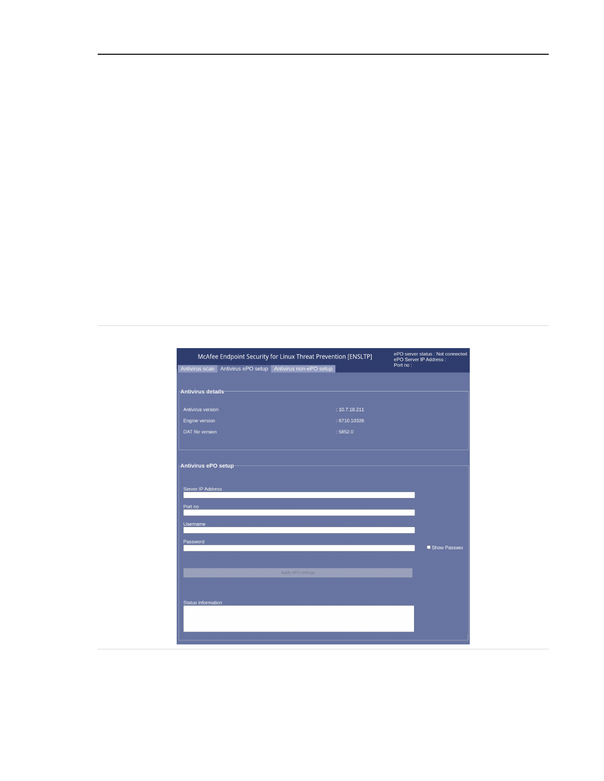
2 System setup
Antivirus Scan Results Details
Last On-Demand Scan Result
Shows relevant details for the most recent OnDemand scan including Time scan started,
Time scan ended, Scan completed time, Files scanned, Files executed, Errors, Timeouts,
Infected files, and a link to the most recent On-Demand Scan Log.
Recent On-Access Scan Result
Not currently used.
List of Files Being Scanned
These files are included in the scan: OS libraries, Application software, Servers, and Con-
figuration files.
List of Files Excluded from Scan
Some files are inaccessible to outside users and do not need to be scanned. These include
System log files, Application log files, and Image data.
Touch the Antivirus EPO Setup tab to display the Antivirus EPO Setup screen.
Figure 2-43: Antivirus EPO Setup screen
Antivirus Details
Shows the latest versions of the antivirus software, antivirus engine, and DAT file.
2-57
Page 100
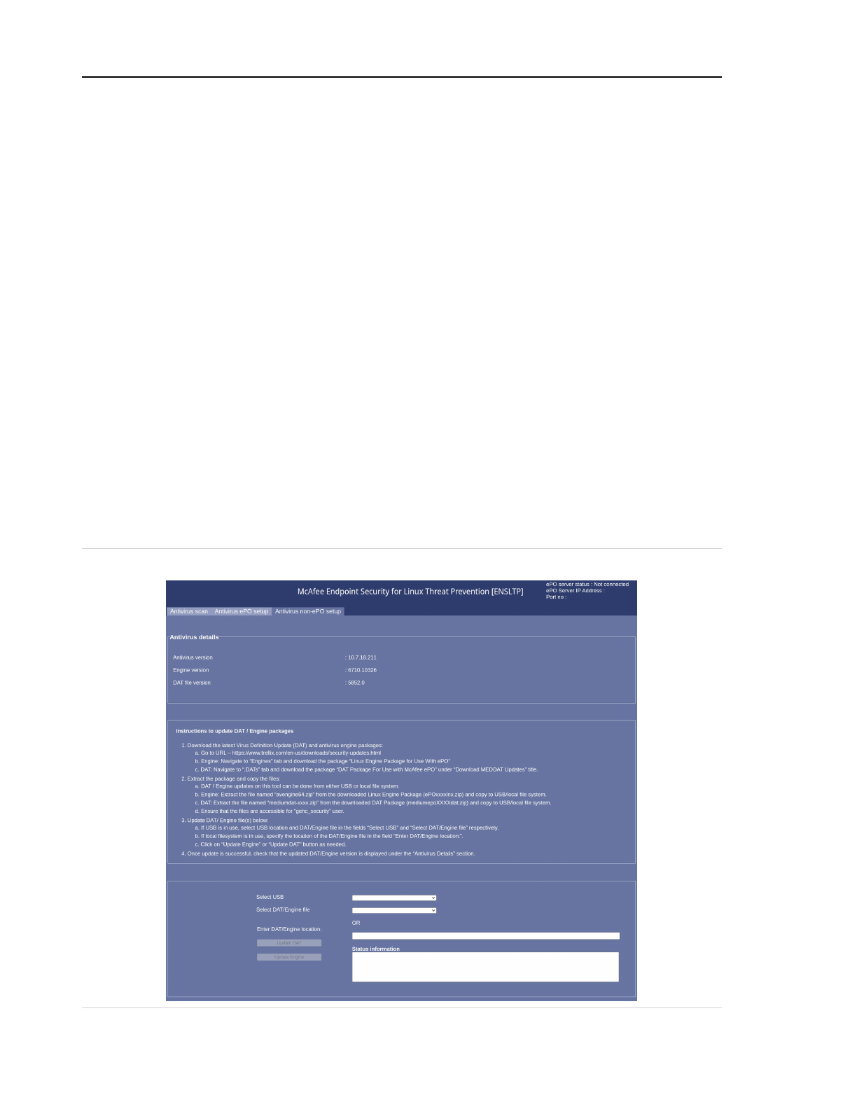
2 System setup
Antivirus EPO Setup
Server IP Address
The IP address for the McAfee ePO server.
Port No
Enter 8443, the port number for the McAfee ePO server.
Username
The username for the McAfee ePO server.
Password
The password for the McAfee ePO server.
Show Password
Select to show the password.
Apply EPO Settings
Touch to save these settings.
Status Information
Shows status of the current update, when an update is in process.
Touch the Antivirus Non-EPO Setup tab to display the Antivirus Non-EPO Setup screen.
Figure 2-44: Antivirus Non-EPO Setup screen
2-58
 Loading...