

Page 1
NetworX NX-548E Receiver
A
Installation Instructions
466-2225B July 2006
Copyright © 2006, GE Security Inc.
Contents
Introduction. . . . . . . . . . . . . . . . . . . . . . . . . . . . . . . . . . . . . 1
Internal mounting . . . . . . . . . . . . . . . . . . . . . . . . . . . . . . . . 1
External mounting. . . . . . . . . . . . . . . . . . . . . . . . . . . . . . . . 2
Wiring . . . . . . . . . . . . . . . . . . . . . . . . . . . . . . . . . . . . . . . . . 3
DIP switch settings . . . . . . . . . . . . . . . . . . . . . . . . . . . . . . . 3
Power up. . . . . . . . . . . . . . . . . . . . . . . . . . . . . . . . . . . . . . . 3
Programming . . . . . . . . . . . . . . . . . . . . . . . . . . . . . . . . . . . 4
Testing and troubleshooting . . . . . . . . . . . . . . . . . . . . . . . . 6
Programming settings table . . . . . . . . . . . . . . . . . . . . . . . . 7
Supported devices. . . . . . . . . . . . . . . . . . . . . . . . . . . . . . . 11
Specifications . . . . . . . . . . . . . . . . . . . . . . . . . . . . . . . . . . 12
Introduction
The NX-548E Receiver adds wireless capabilities to the
NetworX line of control panels. Adding a receiver makes these
control panels compatible with NX wireless transmitters.
Only three wire connections are required for power and communication to the control panel.
WARNING: To avoid possible equipment damage
W
or personal injury, remove power from
the control panel before making any
wiring connections to the receiver.
Internal mounting
For internal mounting, mount the receiver inside the control
panel enclosure. Use the following installation guidelines:
• Leave at least 10 in. (25 cm) above the control panel for the
receiver’s antennas.
• Avoid areas that expose the receiver to moisture.
• Avoid areas with excessive metal or electrical wiring,
including furnaces and utility rooms.
To mount the receiver, do the following:
1. Remove the appropriate knockouts on the top of the control
panel enclosure for the antenna shrouds.
2. Assemble the antenna shrouds and fit the black O-rings to
the bottom of each shroud.
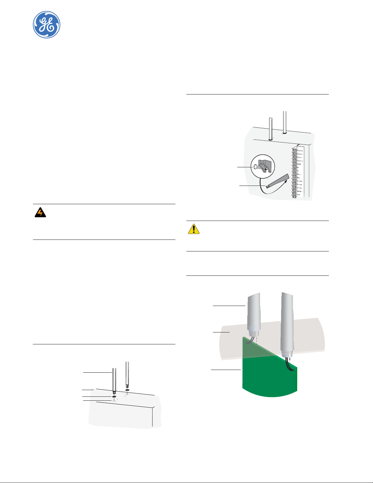
3. Insert the shrouds into the knockout holes (Figure 1).
4. Use the mounting screw provided to loosely install the edge
guide standoff in the lower mounting hole in the appropriate
space to the left of the control panel (Figure 2). Do not
tighten the mounting screw down at this time.
Figure 2. Installing the edge guide standoff
Mounting screw
Edge guide standoff
CAUTION
5. Slide the printed circuit board into the antennae shroud
slots, after inserting wires into antennae shrouds (Figure 3).
Figure 3. Anntennae shrouds
Antennae
shrouds
Enclosure
You must be free of static electricity before
handling circuit boards. Touch a bare metal
surface or wear a grounding strap to
discharge yourself.
Figure 1. Installing the antenna shrouds
Antenna shroud
Enclosure top
O-ring
Knockout hole
Circuit
board
Page 2
NetworX NX-548E Receiver
2
Installation Instructions
6. Align the bottom of the circuit board in the edge guide
standoff and twist the standoff into place (Figure 4). Tighten
the mounting screw (Figure 2).
Figure 4. Installing the circuit board
Antenna shroud
Enclosure
Circuit board
Edge guide standoff
External mounting
This installation uses enclosure model NX-569 (600-1029-03).
The module comes as a kit that is assembled in the field. Use the
following installation guidelines:
• Allow at least 10 in. (25 cm) of clearance above the enclosure for the antennas.
• Use the wire length guidelines in Table 1.
Table 1. Wire lengths
Wire gauge (shielded or unshielded)
22 AWG (0.65 mm) 250 feet (76 m)
18 AWG (1.02 mm) 500 feet (152 m)
• Install the module in its own plastic enclosure. It should not
be installed inside the panel’s enclosure.
• Avoid m ounting locations that expose th e mod ule to moisture.
• Avoid areas with excessive metal or electrical wiring
including furnace and utility rooms. If unavoidable, mount
on or near metal with the antenna extending above the
metallic surfaces as shown in Figure 5.
Maximum wire length between
module and panel
Mounting
The module can be mounted on any interior wall (protected from
the elements). To mount the module, do the following:
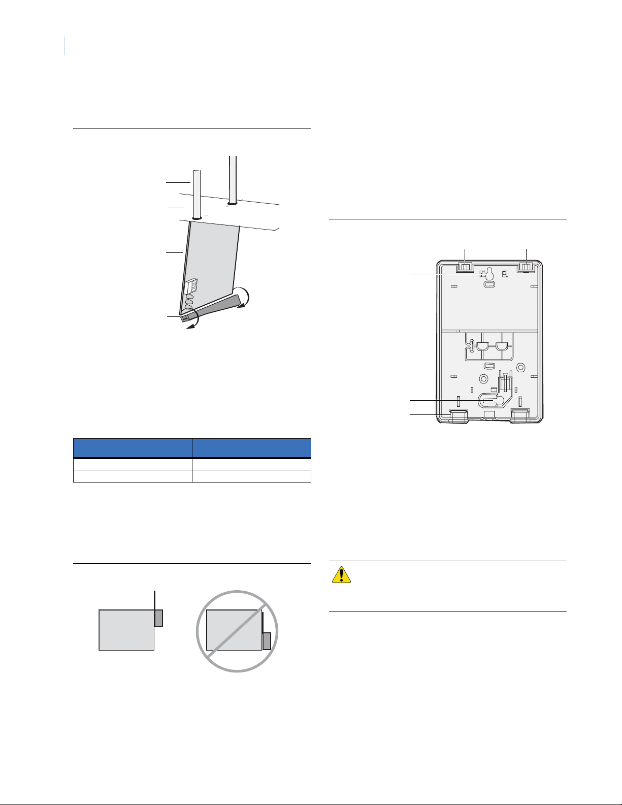
1. Remove the module back plate from the packaging.
2. Hold the base against the mounting surface and mark the
two mounting holes and the wire access hole as shown in
Figure 6. Remember to leave at least 10 in. (25 cm) above
the back plate for the antennas.
Note: The wire access hole is molded into the plastic so that
Figure 6. Back plate
3. Drill holes and insert the appropriate anchors (included).
4. Run a 3-conductor, 22 or 18 gauge (0.65 or 1.02 mm)
stranded wire cable from the module wire access hole location to the panel (Figure 6).
5. Secure the back plate to the wall with the pan head screws
provided.
6. To assemble the antenna shrouds, attach the proper number
of sections together, then attach the top cap.
7. Install each antenna shroud on top of the back plate.
8.
Remove the transceiver circuit board from the an tis ta tic bag.
you can access the wire, yet keep it hidden from the
back plate.
Antenna shroud locations
Mounting hole
Mounting hole
Wire access
Figure 5. Mounting on or near metal
Metal Metal
Tools and supplies needed
To complete the installation, you will need the following tools
and supplies:
• Screwdrivers;
• Drill with bits;
• Mounting screws and anchors (included); and
• 3-conductor, 22-gauge (0.65 mm) or larger, stranded wire.
CAUTION
You must be free of static electricity before
handling circuit boards. Wear a grounding
strap or touch a bare metal surface to
discharge static electricity.
Page 3
3
ON ECE
1 2 3 4
4
4
4
4
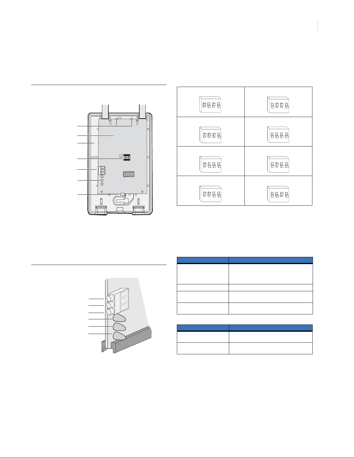
9. To install the circuit board onto the back plate (Figure 7),
insert the antennas into the antenna shrouds, then gently
slide the top of the circuit board under the two top latches,
and snap the circuit board in at the bottom latch to secure it
in place.
Figure 7. Circuit board and back plate
Antenna shrouds
Top latches
Circuit board
Back plate
DIP switches
ON ECE
1 2 3 4
Wiring terminals
LEDs
Bottom latch
Wiring
To wire the receiver, do the following:
1. Remove power (if applied) from the control panel.Use 22gauge, or larger, stranded wire to connect the +12, GND,
and DA TA terminals on the receiver (Figure 8) to the power,
common, and data terminals on the control panel.
Figure 8. Receiver wiring connections and LEDs
+ 12 (to panel POS)
GND (to panel COM)
DATA (to panel DATA)
Green (power) LED
Red (data) LED
Red (not used) LED
DIP switch settings
The DIP switches (Figure 7) on the circuit board are used to set
the receiver module number. Use Table 2 to set the DIP switches
to the desired module number.
Table 2. DIP switch settings
Module number 32 Module number 33
ON
EDG
43
12
Module number 34 Module number 35 (default)
ON
EDG
43
12
Module number 36 Module number 37
ON
EDG ON
3
1 2
Module number 38 Module number 39
ON
EDG
3
1 2
ON
12
ON
1 2
1 2
ON
12
EDG
43
EDG
3
EDG
3
EDG
43
Power up
When you apply power to the control panel, the green (power)
LED on the receiver (Figure 8) blinks for approximately 10
seconds. Table 3 describes the receiver status based on LED
conditions.The lower red LED at the bottom of the receiver
(Figure 8) may emit a dim glow, but is not used as an indicator.
Table 3. LED indications
Green (power) LED status Meaning
Power-up blinks LED blinks represent Product Version Number
Off No packets from sensors being received.
Short blink on Receiver received a valid packet from an
Long blink on Receiver received a valid packet from an
Red (data) LED status Meaning
Off No data communication with the control panel.
Short blink on Normal data communication with the control
(PVN). Long blink on is 1, short blink on is 0. PVN
is in binary, from most significant to least significant bit.
unknown sensor.
enrolled sensor.
Check wiring and power source.
panel.
Page 4

NetworX NX-548E Receiver
4
Installation Instructions
Programming
This section describes how to program the units.
Programming guidelines
Use the following programming guidelines:
• NX-4 and NX-6 control panels can have receivers added
with zones that overlap those contained in the control panel.
No hardware expanders can be used.
• NX-8 control panels can have expansion zones (hardwire or
wireless) set the same as those contained in the control
panel. To do this you mu st disable the onboard control panel
zones in panel location 37. All zone expansion modules
must not overlap any blocks of 8 zones.
• All other control panels can have wireless zones added to
any zone. If a hardwire input (on either the control panel or
hardwire expander) is also present on the same zone as an
enabled wireless zone, the wireless transmitter takes
priority.
Transmitter programming
When programming wireless transmitters into the receiver, you
can set various options and partitions for each transmitter. These
settings appear in segments of each programming location.
Use Table 5 on page 7 to record zone assignments and settings.
Be sure to circle where each zone resides:
RM. Receiver module
HE. Hardwire expander
P. Panel
This gives you all the programming information in one place to
facilitate the programming process.
Zone locations 1 to 192
Zone locations 1 to 192 are not numbered in Table 5 on page 7
since these locations vary depending on location 194, Receiver
zone bank setting.
Note: The default settings shown for segments 1 and 2 in the first
zone location apply to all zone locations.
Add transmitters
LCD touchpads will display instructions when accomplishing tasks.
To add transmitters, do the following:
1. Enter * 8 at the keypad. On LED touchpads, the five func-
tion lights start flashing.
2. Enter the program code (factory default is 9 7 1 3). On LED
touchpads, the service light flashes and the five function
lights change from flashing to on steady.
3. Enter the DIP switch setting module number and press #.
On LED touchpads, the Armed LED turns on, indicating the
control panel is waiting for a programming location entry.
4. For new installations, enter 9 1 0 # to load factory defaults
and clear any unwanted information in memory.
5. For new installations, set the receiver zone bank setting in
location 194 to determine the starting zone number for the
specific receiver . This applies only to NX-8E. This must be
set before learning sensors. For example, if location 194 is
set to 3, the first available location is 25. The total number
of available locations depends on the zone limits for both
the panel and receiver.
6. Enter 0 # to enter the sensor learning location. On LED
touchpads, the Ready LED turns on and the Armed LED
turns off.
7. Enter the zone number (1 through 192) and press *. Three
beeps from the keypad indicate an entry error . This occurs if
you enter a transmitter number that is not within the
receiver’s zone block or if the location already has a sensor
learned into it.
Note: If you change your mind about your entry, terminate
programming by entering 0 # 0 * and start over at
step 6.
8. Trip the desired transmitter (within 250 seconds) as
described
tion
Note: For specific instructions on tripping a transmitter,
Table 4. Tripping transmitters
Transmitter Action
Door/window, shock, glass
guard, freeze, UFT (Universal
Fire Transmitter)
Door/window with external
contact
Recessed door/window Activate tamper switch by removing circuit
Micro door/window and
Micro recessed door/window
SlimLine door/window Remove cover, then press the button on
PIR Activate tamper switch by removing back
Smoke detector without
tamper switch
Smoke detector with tamper
switch
Heat detector Press, then release the tamper switch.
Single button panic Press and hold the button.
Dual button panic Press and hold both buttons together.
Keyfobs Press and hold the lock and unlock buttons
Repeater Press, then release the tamper switch.
in
Table 4
. Listen for the
.
consult the transmitter’s manual.
Activate tamper switch by removing cover.
Activat e tamp er swi tch by remo ving c over.
Feature 4—Input option 1, must be on.
board until tamper switch is exposed.
Refer to the installation instructions for the
specific sensor for activation information.
the top of the sensor, or activate the
tamper switch by removing the cover.
plate from PIR.
Press and hold the test button.
Trip the tamper switch. Feature 4—Input
option 1, must be on.
together.
ding dong
for confirma-
9. To program remaining transmitte rs, repeat steps 6 to 8.
10. To exit program mode, press EXIT EXIT.
11. Confirm that the zone types and partition assignments are
set correctly in the control panel. Refer to the control panel
installation manual for instructions on how to set zone types
and partition assignments.
Note: When an 80-bit device is added, Feature 6 of Segment 1
(see Table 5 on page 7) is turned on. But when a 63-bit
device is added on a zone location that previously had an
80-bit device, make sure to turn off Feature 6 of Segment 1.
Page 5

5
Transmitter options
LCD touchpads will display instructions when accomplishing
tasks.
To program the transmitter and partition settings, do the
following:
1. Enter * 8 at the keypad. On LED touchpads, the five func-
tion lights start flashing.
2. Enter the program code (factory default is 9713). On LED
touchpads, the service light flashes and the five function
lights change from flashing to on steady.
3. Enter the DIP switch setting module number for the receiver
and press #. On LED touchpads, the Armed LED turns on to
indicate the control panel is waiting for a programming
location entry.
4. Enter the zone location number and press #. On LED touch-
pads, the Armed LED turns on and the Zone LEDs display
the binary data for the current settings.
5. Press the keypad button that corresponds to the feature
number you want changed. On LED touchpads, the lights
corresponding to the feature number will turn on or off
depending on the previous state. On LCD touchpads, the
feature number will turn on or off depending on the
previous state.
6. Press * to enter the changes and automatically advance to
segment 2.
Note: If you press # instead of * in step 6, it exits the zone
location and does not save changes to transmitter
options.
7. Press # to exit zone location. To continue programming
other zone locations, repeat steps 4 to7. To exit program
mode, press EXIT EXIT.
Door/window transmitter settings
Use the following guidelines when setting features 4 and 5 (see
Segment 1 in Table 5 on page 7) for door/window transmitters:
• Feature 4 - Input option 1. Turn on this feature to disable the
transmitter’s internal reed switches.
• Feature 5 - Input option 2. For transmitters that use a
normally open (N/O) external contact, leave this feature of f.
For transmitters that use a normally closed (N/C) external
contact, turn this feature on.
Wireless smoke detector settings
Use the following guideline when setting feature 4 (see Segment
1 in Table 5 on page 7) for wireless smoke detectors:
• Feature 4 - Input option 1. For detectors with tamper
switches, turn on this feature to enable the tamper feature.
Note: Feature 4 must be off (disabled) when using wireless smoke
detectors without tamper switches.
4-button keyfob settings
The control panel installation manual describes how keyfob
functions 1 and 2 can be used to control relays, outputs, or X-10
.
devices
Use the following guidelines when setting features 4 and 5 (see
Segment 1 in Table 5 on page 7) for 4-button keyfobs:
• Feature 4 - Input option 1. Turn on this feature to change the
Light button to keyfob function 1.
• Feature 5 - Input option 2. Turn on this feature to change the
Star button to keyfob function 2.
UFT settings
Use the following guidelines when setting features 4, 5 and 7
(see Segment 1 in Table 5 on page 7) for UFTs:
• Feature 4 - Input option 1. For UFTs, turn on this feature to
disable the transmitter’s primary reed.
• Feature 5 - Input option 2. For UFTs on this feature to
disable the transmitter’s secondary reed.
• Feature 7 - Input option 3. For UFTs that use a normally
open (NO) external contact, leave this feature off. For UFTs
that use a normally closed (NC) external contact, turn this
feature on.
Partition settings for keyfobs
LCD touchpads will display instructions when accomplishing tasks.
To program the transmitter and partition settings, do the following:
1. Enter * 8 at the keypad. On LED touchpads, the five func-
tion lights start flashing.
2. Enter the program code (factory default is 9 7 1 3). On LED
touchpads, the service light flashes and the five function
lights change from flashing to on steady.
3. Enter the DIP switch setting module number and press #.
On LED touchpads, the Armed LED turns on to indicate the
control panel is waiting for a programming location entry.
4. Enter the zone location number and press #. On LED touch-
pads, the Armed LED turns on and the Zone LEDs display
the binary data for the current settings. On LCD touchpads,
the display shows Segment 1 and its settings.
5. Press * to advance to Segment 2.
6. Press the keypad button that corresponds to the partition
number you want to change. On LED touchpads, lights that
turn off indicate the keyfob is active in tha t part ition. On
LCD touchpads, partition numbers that turn on indicate the
keyfob is active in that partition.
Note: These partition settings apply only to keyfobs.
Partition assignments for other types of transmitters
are made in the panel.
7. Press * to enter the changes. To continue programming
transmitter partition settings, repeat steps 4 to 8.
Note: If you press #, it does not save changes to the current
segment, but it does save changes to previous
segments.
8. To exit program mode, press EXIT EXIT.
Page 6

NetworX NX-548E Receiver
6
Installation Instructions
Transmitter supervision windows
LCD touchpads will display instructions when accomplishing tasks.
To change the transmitter supervision windows, do the following:
1. Enter * 8 at the keypad. On LED touchpads, the five func-
tion lights start flashing.
2. Enter the program code (factory default is 9 7 1 3).
3. Enter the DIP switch setting module number and press #.
On LED touchpads, the Armed LED turns on to indicate the
control panel is waiting for a programming location entry.
4. Enter 195 # to enter location 195, segment 1.
5. Enter the new normal supervision time (0 to 255 hours) and
press *. If you choose 0, the normal supervision window is
set to 256 hours.
CAUTION
6. Enter the new fire supervision time (0 to 255 hours) and
press *. If you choose 0, the fire supervision window is set
to 256 hours.
7. Enter the new short supervision time (up to 30 minutes).
The short supervision time prevents arming if a transmitter
has not checked in within the set time. This applies only to
specific countries outside the US. Check the control panel
installation manual to determine if this setting is available.
If you enter a number higher than 30 (the default value is
40), you disable the feature.
8. Press * to save any changes. The panel waits for the next
location entry.
Note: If you press #, it does not save changes to the current
9. To exit program mode, press EXIT EXIT.
Do not set the normal or fire supervision
windows to 1 hour. This causes false trouble
reports from all learned wireless transmitters.
segment, but it does save changes made in previous
segments.
Delete transmitters
LCD touchpads will display instructions when accomplishing tasks.
The following section describes how to delete transmitters from
the receiver.
Note: This procedure makes the receiver ignore a transmitter, but
does not remove the transmitter identification from the
receiver’s memory. The transmitter can be reactivated by
turning segment 1 on zone back on, or a new one can be
learned into the zone.
To delete transmitters, do the following:
1. Enter
* 8
at the keypad. On LED touchpads, the five function
lights start flashing.
2. Enter the program code (factory default is 9 7 1 3). On LED
touchpads, the service light flashes and the five function
lights change from flashing to on steady.
3. Enter the DIP switch setting module number and press #.
On LED touchpads, the Armed LED turns on, indicating the
control panel is waiting for a programming location entry.
4. Enter the zone location number to be deleted and press #.
On LED touchpads, the Armed LED turns on and the Zone
LEDs display the binary data for the current settings.
5. T o change transmitter feature 1 (enable sensor), press 1. On
LED touchpads, the 1 LED turns off to indicate the feature
change and the Ready LED flashes to indicate the change
request.
6. Enter * #. On LED touchpads, the Ready LED stops
flashing to indicate the new settings are stored in memory
and the system automatically exits from that location.
7. To continue deleting transmitters, repeat steps 4 to 6.
8. If you want to delete all transmitters and load factory
defaults, enter 9 1 0 #.
9. To exit program mode, press EXIT EXIT.
Testing and troubleshooting
Test all transmitters to verify programming and operation. Use
location 200 to troubleshoot transmitters mounted in marginal
signal strength locations or if the panel has a sensor lost trouble
condition. To troubleshoot the transmitters, do the following:
• Delete the transmitter and relearn it back into the receiver.
• Go to location 200 and check the signal strength. A signal of
6 or more indicates good signal strength, anything less
could cause periodic sensor lost trouble conditions.
• If signal strength is below the acceptable level, delete the
transmitter and rotate the mounting position (90, 180, or 270
degrees).
• Relearn the transmitter into the receiver and check loca tion
200 for signal strength.
• If rotating the mounting position does not improve signal
reception or is not practical, move the transmitter to
different locations near the desired mounting area.
• Delete and relearn the transmitter until an acceptable signal
level is attained, then mount the transmitter.
Page 7

7
Programming settings table
Table 5. Programming settings
Location Segment 1 Segment 2
0
(Transmitter to
program)
Zone _____
Assigned to module
#_____.
RM HE P
Zone _____
Assigned to module
#_____.
RM HE P
Zone _____
Assigned to module
#_____.
RM HE P
Zone _____
Assigned to module
#_____.
RM HE P
Zone _____
Assigned to module
#_____.
RM HE P
Zone _____
Assigned to module
#_____.
RM HE P
None None
1 - Enable sensor
(default = off)
2 - Supervised
(default = on)
3 - Fire supervision
(default = off)
4 - Input option 1
(default = off)
5 - Input option 2
(default = off)
6 - 80-bit device
(default = off)
7 - Input option 3
(default = off)
8 - Not used
1 - Enable sensor
2 - Supervised
3 - Fire supervision
4 - Input option 1
5 - Input option 2
6 - 80-bit device
7 - Input option 3
8 - Not used
1 - Enable sensor
2 - Supervised
3 - Fire supervision
4 - Input option 1
5 - Input option 2
6 - 80-bit device
7 - Input option 3
8 - Not used
1 - Enable sensor
2 - Supervised
3 - Fire supervision
4 - Input option 1
5 - Input option 2
6 - 80-bit device
7 - Input option 3
8 - Not used
1 - Enable sensor
2 - Supervised
3 - Fire supervision
4 - Input option 1
5 - Input option 2
6 - 80-bit device
7 - Input option 3
8 - Not used
1 - Enable sensor
2 - Supervised
3 - Fire supervision
4 - Input option 1
5 - Input option 2
6 - 80-bit device
7 - Input option 3
8 - Not used
Partition 1 keyfob
Partition 2 keyfob
Partition 3 keyfob
Partition 4 keyfob
Partition 5 keyfob
Partition 6 keyfob
Partition 7 keyfob
Partition 8 keyfob
Partition 1 keyfob
Partition 2 keyfob
Partition 3 keyfob
Partition 4 keyfob
Partition 5 keyfob
Partition 6 keyfob
Partition 7 keyfob
Partition 8 keyfob
Partition 1 keyfob
Partition 2 keyfob
Partition 3 keyfob
Partition 4 keyfob
Partition 5 keyfob
Partition 6 keyfob
Partition 7 keyfob
Partition 8 keyfob
Partition 1 keyfob
Partition 2 keyfob
Partition 3 keyfob
Partition 4 keyfob
Partition 5 keyfob
Partition 6 keyfob
Partition 7 keyfob
Partition 8 keyfob
Partition 1 keyfob
Partition 2 keyfob
Partition 3 keyfob
Partition 4 keyfob
Partition 5 keyfob
Partition 6 keyfob
Partition 7 keyfob
Partition 8 keyfob
Partition 1 keyfob
Partition 2 keyfob
Partition 3 keyfob
Partition 4 keyfob
Partition 5 keyfob
Partition 6 keyfob
Partition 7 keyfob
Partition 8 keyfob
(default = on)
(default = off)
(default = off)
(default = off)
(default = off)
(default = off)
(default = off)
(default = off)
Table 5. Programming settings (continued)
Location Segment 1 Segment 2
Zone _____
Assigned to module
#_____.
RM HE P
Zone _____
Assigned to module
#_____.
RM HE P
Zone _____
Assigned to module
#_____.
RM HE P
Zone _____
Assigned to module
#_____.
RM HE P
Zone _____
Assigned to module
#_____.
RM HE P
Zone _____
Assigned to module
#_____.
RM HE P
Zone _____
Assigned to module
#_____.
RM HE P
1 - Enable sensor
2 - Supervised
3 - Fire supervision
4 - Input option 1
5 - Input option 2
6 - 80-bit device
7 - Input option 3
8 - Not used
1 - Enable sensor
2 - Supervised
3 - Fire supervision
4 - Input option 1
5 - Input option 2
6 - 80-bit device
7 - Input option 3
8 - Not used
1 - Enable sensor
2 - Supervised
3 - Fire supervision
4 - Input option 1
5 - Input option 2
6 - 80-bit device
7 - Input option 3
8 - Not used
1 - Enable sensor
2 - Supervised
3 - Fire supervision
4 - Input option 1
5 - Input option 2
6 - 80-bit device
7 - Input option 3
8 - Not used
1 - Enable sensor
2 - Supervised
3 - Fire supervision
4 - Input option 1
5 - Input option 2
6 - 80-bit device
7 - Input option 3
8 - Not used
1 - Enable sensor
2 - Supervised
3 - Fire supervision
4 - Input option 1
5 - Input option 2
6 - 80-bit device
7 - Input option 3
8 - Not used
1 - Enable sensor
2 - Supervised
3 - Fire supervision
4 - Input option 1
5 - Input option 2
6 - 80-bit device
7 - Input option 3
8 - Not used
Partition 1 keyfob
Partition 2 keyfob
Partition 3 keyfob
Partition 4 keyfob
Partition 5 keyfob
Partition 6 keyfob
Partition 7 keyfob
Partition 8 keyfob
Partition 1 keyfob
Partition 2 keyfob
Partition 3 keyfob
Partition 4 keyfob
Partition 5 keyfob
Partition 6 keyfob
Partition 7 keyfob
Partition 8 keyfob
Partition 1 keyfob
Partition 2 keyfob
Partition 3 keyfob
Partition 4 keyfob
Partition 5 keyfob
Partition 6 keyfob
Partition 7 keyfob
Partition 8 keyfob
Partition 1 keyfob
Partition 2 keyfob
Partition 3 keyfob
Partition 4 keyfob
Partition 5 keyfob
Partition 6 keyfob
Partition 7 keyfob
Partition 8 keyfob
Partition 1 keyfob
Partition 2 keyfob
Partition 3 keyfob
Partition 4 keyfob
Partition 5 keyfob
Partition 6 keyfob
Partition 7 keyfob
Partition 8 keyfob
Partition 1 keyfob
Partition 2 keyfob
Partition 3 keyfob
Partition 4 keyfob
Partition 5 keyfob
Partition 6 keyfob
Partition 7 keyfob
Partition 8 keyfob
Partition 1 keyfob
Partition 2 keyfob
Partition 3 keyfob
Partition 4 keyfob
Partition 5 keyfob
Partition 6 keyfob
Partition 7 keyfob
Partition 8 keyfob
Page 8

NetworX NX-548E Receiver
8
Installation Instructions
Table 5. Programming settings (continued)
Location Segment 1 Segment 2
Zone _____
Assigned to module
#_____.
RM HE P
Zone _____
Assigned to module
#_____.
RM HE P
Zone _____
Assigned to module
#_____.
RM HE P
Zone _____
Assigned to module
#_____.
RM HE P
Zone _____
Assigned to module
#_____.
RM HE P
Zone _____
Assigned to module
#_____.
RM HE P
Zone _____
Assigned to module
#_____.
RM HE P
1 - Enable sensor
2 - Supervised
3 - Fire supervision
4 - Input option 1
5 - Input option 2
6 - 80-bit device
7 - Input option 3
8 - Not used
1 - Enable sensor
2 - Supervised
3 - Fire supervision
4 - Input option 1
5 - Input option 2
6 - 80-bit device
7 - Input option 3
8 - Not used
1 - Enable sensor
2 - Supervised
3 - Fire supervision
4 - Input option 1
5 - Input option 2
6 - 80-bit device
7 - Input option 3
8 - Not used
1 - Enable sensor
2 - Supervised
3 - Fire supervision
4 - Input option 1
5 - Input option 2
6 - 80-bit device
7 - Input option 3
8 - Not used
1 - Enable sensor
2 - Supervised
3 - Fire supervision
4 - Input option 1
5 - Input option 2
6 - 80-bit device
7 - Input option 3
8 - Not used
1 - Enable sensor
2 - Supervised
3 - Fire supervision
4 - Input option 1
5 - Input option 2
6 - 80-bit device
7 - Input option 3
8 - Not used
1 - Enable sensor
2 - Supervised
3 - Fire supervision
4 - Input option 1
5 - Input option 2
6 - 80-bit device
7 - Input option 3
8 - Not used
Partition 1 keyfob
Partition 2 keyfob
Partition 3 keyfob
Partition 4 keyfob
Partition 5 keyfob
Partition 6 keyfob
Partition 7 keyfob
Partition 8 keyfob
Partition 1 keyfob
Partition 2 keyfob
Partition 3 keyfob
Partition 4 keyfob
Partition 5 keyfob
Partition 6 keyfob
Partition 7 keyfob
Partition 8 keyfob
Partition 1 keyfob
Partition 2 keyfob
Partition 3 keyfob
Partition 4 keyfob
Partition 5 keyfob
Partition 6 keyfob
Partition 7 keyfob
Partition 8 keyfob
Partition 1 keyfob
Partition 2 keyfob
Partition 3 keyfob
Partition 4 keyfob
Partition 5 keyfob
Partition 6 keyfob
Partition 7 keyfob
Partition 8 keyfob
Partition 1 keyfob
Partition 2 keyfob
Partition 3 keyfob
Partition 4 keyfob
Partition 5 keyfob
Partition 6 keyfob
Partition 7 keyfob
Partition 8 keyfob
Partition 1 keyfob
Partition 2 keyfob
Partition 3 keyfob
Partition 4 keyfob
Partition 5 keyfob
Partition 6 keyfob
Partition 7 keyfob
Partition 8 keyfob
Partition 1 keyfob
Partition 2 keyfob
Partition 3 keyfob
Partition 4 keyfob
Partition 5 keyfob
Partition 6 keyfob
Partition 7 keyfob
Partition 8 keyfob
Page 9

9
Table 5. Programming settings (continued)
Location Segment 1 Segment 2
Zone _____
Assigned to module
#_____.
RM HE P
Zone _____
Assigned to module
#_____.
RM HE P
Zone _____
Assigned to module
#_____.
RM HE P
Zone _____
Assigned to module
#_____.
RM HE P
Zone _____
Assigned to module
#_____.
RM HE P
Zone _____
Assigned to module
#_____.
RM HE P
Zone _____
Assigned to module
#_____.
RM HE P
1 - Enable sensor
2 - Supervised
3 - Fire supervision
4 - Input option 1
5 - Input option 2
6 - 80-bit device
7 - Input option 3
8 - Not used
1 - Enable sensor
2 - Supervised
3 - Fire supervision
4 - Input option 1
5 - Input option 2
6 - 80-bit device
7 - Input option 3
8 - Not used
1 - Enable sensor
2 - Supervised
3 - Fire supervision
4 - Input option 1
5 - Input option 2
6 - 80-bit device
7 - Input option 3
8 - Not used
1 - Enable sensor
2 - Supervised
3 - Fire supervision
4 - Input option 1
5 - Input option 2
6 - 80-bit device
7 - Input option 3
8 - Not used
1 - Enable sensor
2 - Supervised
3 - Fire supervision
4 - Input option 1
5 - Input option 2
6 - 80-bit device
7 - Input option 3
8 - Not used
1 - Enable sensor
2 - Supervised
3 - Fire supervision
4 - Input option 1
5 - Input option 2
6 - 80-bit device
7 - Input option 3
8 - Not used
1 - Enable sensor
2 - Supervised
3 - Fire supervision
4 - Input option 1
5 - Input option 2
6 - 80-bit device
7 - Input option 3
8 - Not used
Partition 1 keyfob
Partition 2 keyfob
Partition 3 keyfob
Partition 4 keyfob
Partition 5 keyfob
Partition 6 keyfob
Partition 7 keyfob
Partition 8 keyfob
Partition 1 keyfob
Partition 2 keyfob
Partition 3 keyfob
Partition 4 keyfob
Partition 5 keyfob
Partition 6 keyfob
Partition 7 keyfob
Partition 8 keyfob
Partition 1 keyfob
Partition 2 keyfob
Partition 3 keyfob
Partition 4 keyfob
Partition 5 keyfob
Partition 6 keyfob
Partition 7 keyfob
Partition 8 keyfob
Partition 1 keyfob
Partition 2 keyfob
Partition 3 keyfob
Partition 4 keyfob
Partition 5 keyfob
Partition 6 keyfob
Partition 7 keyfob
Partition 8 keyfob
Partition 1 keyfob
Partition 2 keyfob
Partition 3 keyfob
Partition 4 keyfob
Partition 5 keyfob
Partition 6 keyfob
Partition 7 keyfob
Partition 8 keyfob
Partition 1 keyfob
Partition 2 keyfob
Partition 3 keyfob
Partition 4 keyfob
Partition 5 keyfob
Partition 6 keyfob
Partition 7 keyfob
Partition 8 keyfob
Partition 1 keyfob
Partition 2 keyfob
Partition 3 keyfob
Partition 4 keyfob
Partition 5 keyfob
Partition 6 keyfob
Partition 7 keyfob
Partition 8 keyfob
Page 10

NetworX NX-548E Receiver
10
Installation Instructions
Table 5. Programming settings (continued)
Location Segment 1 Segment 2
Zone _____
Assigned to module
#_____.
RM HE P
Zone _____
Assigned to module
#_____.
RM HE P
Zone _____
Assigned to module
#_____.
RM HE P
Zone _____
Assigned to module
#_____.
RM HE P
Zone _____
Assigned to module
#_____.
RM HE P
Zone _____
Assigned to module
#_____.
RM HE P
Zone _____
Assigned to module
#_____.
RM HE P
1 - Enable sensor
2 - Supervised
3 - Fire supervision
4 - Input option 1
5 - Input option 2
6 - 80-bit device
7 - Input option 3
8 - Not used
1 - Enable sensor
2 - Supervised
3 - Fire supervision
4 - Input option 1
5 - Input option 2
6 - 80-bit device
7 - Input option 3
8 - Not used
1 - Enable sensor
2 - Supervised
3 - Fire supervision
4 - Input option 1
5 - Input option 2
6 - 80-bit device
7 - Input option 3
8 - Not used
1 - Enable sensor
2 - Supervised
3 - Fire supervision
4 - Input option 1
5 - Input option 2
6 - 80-bit device
7 - Input option 3
8 - Not used
1 - Enable sensor
2 - Supervised
3 - Fire supervision
4 - Input option 1
5 - Input option 2
6 - 80-bit device
7 - Input option 3
8 - Not used
1 - Enable sensor
2 - Supervised
3 - Fire supervision
4 - Input option 1
5 - Input option 2
6 - 80-bit device
7 - Input option 3
8 - Not used
1 - Enable sensor
2 - Supervised
3 - Fire supervision
4 - Input option 1
5 - Input option 2
6 - 80-bit device
7 - Input option 3
8 - Not used
Partition 1 keyfob
Partition 2 keyfob
Partition 3 keyfob
Partition 4 keyfob
Partition 5 keyfob
Partition 6 keyfob
Partition 7 keyfob
Partition 8 keyfob
Partition 1 keyfob
Partition 2 keyfob
Partition 3 keyfob
Partition 4 keyfob
Partition 5 keyfob
Partition 6 keyfob
Partition 7 keyfob
Partition 8 keyfob
Partition 1 keyfob
Partition 2 keyfob
Partition 3 keyfob
Partition 4 keyfob
Partition 5 keyfob
Partition 6 keyfob
Partition 7 keyfob
Partition 8 keyfob
Partition 1 keyfob
Partition 2 keyfob
Partition 3 keyfob
Partition 4 keyfob
Partition 5 keyfob
Partition 6 keyfob
Partition 7 keyfob
Partition 8 keyfob
Partition 1 keyfob
Partition 2 keyfob
Partition 3 keyfob
Partition 4 keyfob
Partition 5 keyfob
Partition 6 keyfob
Partition 7 keyfob
Partition 8 keyfob
Partition 1 keyfob
Partition 2 keyfob
Partition 3 keyfob
Partition 4 keyfob
Partition 5 keyfob
Partition 6 keyfob
Partition 7 keyfob
Partition 8 keyfob
Partition 1 keyfob
Partition 2 keyfob
Partition 3 keyfob
Partition 4 keyfob
Partition 5 keyfob
Partition 6 keyfob
Partition 7 keyfob
Partition 8 keyfob
Table 5. Programming settings (continued)
Location Segment 1 Segment 2
193
Receiver options (all
defaults off)
194
Receiver zone bank
setting (default = 0),
set this before
learning any sensors.
Applies only to NX8E.
195
Supervision Windows
1 - Enable jam detect
2 - Enable auto
advance to next
zone number
3 - Keyfob user ID (off
= all keyfobs
report as user 99;
on = keyfob
reports as
learned zone #)
4 - Enable antenna
tamper (only
selectable on
international
versions; reports
as box tamper)
5 - Enable case
tamper
6 - Keyfob disarming
(0 = keyfob
disarm normal; 1
= disarm only
during entry or
partial arm)
7 - Enable wall tamper
(reports as box
tamper)
8 - Not used
Starting zone
numbers by bank
setting:
0 = 1
1 = 9
2 = 17
3 = 25
4 = 33
5 = 41
6 = 49
7 = 57
8 = 65
9 = 73
10 = 81
11 = 89
12 = 97
13 = 105
14 = 113
15 = 121
16 = 129
17 = 137
18 = 145
19 = 153
20 = 161
21 = 169
22 = 177
23 = 185
Normal ______hours.
(0 to 255 hours;
default = 24 hours)
Segment 3:
Short supervision time _____minutes (1 to 30
minutes, default = 40 minutes - disabled)
Do not change Segment 3 setting unless
required. See step 7 under Transmitter supervi-
sion windows on page 6.
None
Fire ______hours.
(0 to 255 hours;
default = 4 hours)
Page 11

11
Table 5. Programming settings (continued)
Location Segment 1 Segment 2
200
Number of rounds
received from last
transmitter learned
See Testing and trou-
bleshooting on page 6.
None None
Supported devices
For 80-bit devices, Feature 6 must be on for Segment 1 on zone
location. For 63-bit devices, Feature 6 must be off for Segment 1
on zone location.
80-bit devices
• 60-849-02-95 ESL Smoke Detector
• 60-917-95 Universal Fire Transmitter
• 60-832-95R 2 Button Keychain Touchpad *
63-bit devices
• NX-450 (60-670-95R) SAW Door/Window Sensor, White
• NX-451 (60-670-11-95R) SAW Door/Window Sensor, Brown
• NX-452 (60-499-10-319.5) SlimLine Door/Window Sensor ,
White
• NX-453 (60-499-11-319.5) SlimLine Door/W indow Sensor ,
Brown
• NX-458 (60-751-95) Recessed Micro Door/Window Sensor
• 60-741-11-95 Rececessed Micro Door/Window
Sensor, Brown
• NX-470 (60-659-95R) 4-Button Keychain Touchpad
• NX-474 (60-906-95) Micro Multi-Purpose Crystal Panic Button
• NX-475 (60-578-10-95) Water-Resistant Pendant Panic Sensor
• NX-480 (60-639-95) Indoor SAW PIR Motion Sensor
• 60-639-95R-OD Outdoor SAW PIR Motion
• 60-639-02-95R SAW PIR Mothion w/1.5v
• NX-487 (60-834-95) Adjustable Dual Technology Sound Sensor
• NX-490 (60-506-319.5) Wireless Smoke Sensor
• NX-491NT (60-848-02-95) ESL 560 Series Wireless
Smoke Sensor
• NX-495 (60-460-319.5) Rate-of-Rise Heat Sensor
• NX-650 (60-362-10-319.5) Standard Door/W indow Sensor,
White
• NX-651 (60-362-11-319.5) Standard Door/Window Sensor,
Brown
• NX-652 (60-641-95) Long Life Door/Window Sensor, White
• NX-653 (60-641-11-95) Long Life Door/Window Sensor,
Brown
• NX-454 (60-688-95) Micro Door/Window Sensor, White*
• NX-455 (60-688-11-95) Micro Door/Window Sensor, Brown*
• NX-481 (60-807-95R) Indoor SAW PIR Motion Sensor*
• NX-482 (60-880-95) AP750W PIR Motion Sensor*
• NX-488 (60-873-95) ShatterP ro Crystal Glass Break Sensor*
• NX-497 (60-652-95) Crystal Carbon Monoxide Sensor*
• NX-656 (60-462-10-319.5) Glass Guard Crystal Sensor, White*
• NX-657 (60-462-11-319.5) Glass Guard Crystal Sensor,
Brown *
• NX-658 (60-742-95R) Crystal Freeze Sensor*
• NX-667 (60-886-95) Crystal Learn Mode Shock Sensor,
White*
• NX-668 (60-886-11-95) Crystal Learn Mode Shock Sensor,
Brown*
• NX-695 (60-744-95R) SAW Water Sensor*
• NX-706 (80-922) Repeater Kit 319.5*
• NX-707 (80-922-1) Repeater Kit 319.5 *
• 60-511-01-95 Learn Mode DS924 PIR Motion Sensor*
• 60-511-01-95 DS924I Pet Immune PIR*
• 60-452-10-319.5 Learn Mode Pendant Panic*
• 60-457-10-319.5 Learn Mode Double Button Panic *
• 60-458-10-319.5 Learn Mode Single Button Panic*
* These devices are not listed, investigated, or verified by UL.
Page 12

NetworX NX-548E Receiver
12
Installation Instructions
Specifications FCC compliance
Compatibility NX-4, NX-6, NX-8, NX-8E control panels
Frequency 319.5 MHz
Wireless range 1,000 feet (304 m)
Required power 12.0 VDC (provided by panel)
Current draw 55 mA maximum
Operating temperature 32 to 120°F (0 to 49°C)
Storage temperature -30 to 140°F (-34 to 60°C)
Max. relative humidity 85% noncondensing
Dimensions 4.65 x 3.20 inches (11.8 x 8.1 cm)
Listings
UL
CUL
UL 985, UL 1023
ORD-C1023-1974, ULC-S545-02
This device complies with part 15 of the FCC rules. Operation is subject to the
following conditions:
1. This device may not cause harmful interference.
2. This device must accept any interference received, including interference
that may cause undesired operation.
Changes or modifications not expressly approved by the party responsible for
compliance could void the user’s authority to operate the equipment.
Toll-free: 888.437.3287 (US, including Alaska and Hawaii; Puerto Rico; Canada).
Outside the toll-free area: Contact your local dealer.
Technical support
www.gesecurity.com
 Loading...