

Page 1

g
Technical
Publications
2278812-100
Revision 0
GE Medical Systems
LOGIQ 200 and LOGIQ 200 PRO
Quality Assurance Manual
Copyright© 2000 by General Electric Company
Operating Documentation
Page 2

g
GE Medical Systems
GE Medical Systems: Telex: 3797371
P.O. Box 414, Milwaukee, Wisconsin 53201 U.S.A.
(Asia, Pacific, Latin America, North America)
GE Medical Systems—Europe: Telex: 695277
283 rue de la Miniére BP34
78533 BUC Cedex
Page 3

LOGIQ α200 or LOGIQ 200 PRO
Quality Assurance Testing Documents
TABLE of CONTENTS
TAB #1 ACR Accreditation Overview 3 pages
TAB #2 Probe ID List 1 Page
QA Testing - 2277615-100 16 Pages
TAB #3 Probe ID List 1 Page
Probe 3 2267008-100 4 Pages
Probe 4 2272728-100 4 Pages
Probe 5 2272729-100 4 Pages
Probe 6 2272730-100 4 Pages
Probe 7 2272732-100 4 Pages
Probe 8 2272733-100 4 Pages
Probe 9 2272735-100 4 Pages
TAB #4 QA Reference Manual - 2262684-100 30 Pages
Probe ID List 1 Page
TAB #5 System Display Format 2 Pages
TAB #6 Section 4 - Service Manuals 20 Pages
TAB #7 Section 2 - Service Manuals 75 Pages
TAB #8 Filling out the ACR Forms 5 Pages
TAB #9 ACR, Section G: Quality Control 3 Pages
ACR, Section H: Equipment Chart 1 Page
TAB #10 Inspection and Calibration Certificate 1 Page
Page 4

Page 5

GE ULTRASOUND QUALITY ASSURANCE
ACR ULTRASOUND ACCREDITATION PROGRAM
The ACR Ultrasound Accreditation Program evaluates qualifications of personnel, equipment,
image quality and quality control measures. It is believed that these are the primary factors
impacting the quality of patient ultrasound imaging.
The Ultrasound Accreditation Program is carried out through the mail (paper submission), with
random on site reviews performed as needed for validation or clarification.
PROGRAM GOALS
• Improvement in the quality of ultrasound performance.
• Provision of educational information by raising awareness of ultrasound issues.
• Recognition of ultrasound facilities which meet program objectives.
• Collection of national data about the practice of ultrasound.
DEFINITION OF AN ULTRASOUND FACILITY
• Ultrasound section within a hospital
• Ultrasound service offered in an outpatient setting, e.g., office, multispecialty clinic, or
imaging center
• Mobile ultrasound service
A separate application is required for each location of ultrasound practice.
ULTRASOUND ACCREDITATION PROCESS
The ultrasound accreditation process consists of three parts which must be completed
successfully in order to receive accreditation.
Application – requests credentials of physicians and sonographer personnel.
Quality Control Evaluation – requests information about ultrasound quality control.
Clinical Image Evaluation – requests specific types of normal ultrasound exams; plus normal and
abnormal exams for vascular accreditation.
QUALITY CONTROL EVALUATION
1. A quality assurance (QA) program should be in place for each scanner in the facility.
The quality assurance program must be directed by a medical physicist or by the supervising
radiologist or physician who may appoint an appropriate designee to oversee the program.
There must be program documentation which describes the goals of the quality assurance
program and the responsibilities involved.
The person responsible for the quality assurance program must work with the preventive
maintenance professional. Routine quality control testing must occur regularly; a minimum
requirement is semiannually. The same tests must be performed during each testing period so
that changes can be monitored over time and effective corrective action can be taken. Testing
results, corrective action, and the effects of corrective action must be documented and
maintained on site.
Page 6

GE ULTRASOUND QUALITY ASSURANCE
ACR ULTRASOUND ACCREDITATION PROGRAM
QUALITY CONTROL EVALUATION (continued)
The QA program must evaluate at least the following items in Gray-Scale Imaging Mode.
Specific QC data will be collected as part of the Full Application that is submitted in the second
phase of the accreditation process.
• System sensitivity and/or penetration capability.
• Image uniformity.
• Photography and other hard copy recording.
• Low contrast object detectability (optional).
• Assurance of electrical and mechanical safety.
In addition, it is recommended that users verify vertical and horizontal distance measurement
accuracy when a QA program is initiated for a scanner. It is not required that these factors be
reassessed during QC testing.
These items may be assessed using commercially available phantoms. At the present time,
there is no single phantom that is preferred; users should select a phantom from current
commercially available units.
2. Test Frequency
QA tests should be done at least semiannually for each scanner as part of the quality
assurance program for the site. Test results must be documented so that trends in equipment
performance can be identified and appropriate corrective action taken.
3. Transducers
On an ongoing basis, tests should be done using two probes commonly used with any
scanner employing more than one transducer. It is recommended that these be of different
scan formats such as one linear (or curvilinear) array and one sector (mechanical, phased or
vector).
4. Data to be Submitted for Accreditation
For each scanner, submit the QC Summary (Section G of the Full Application) which shows
the data acquired from one of the semiannual tests. The QC Summary should document
results from testing the transducer (which includes two probes with different formats). Data
should be taken from testing of the transducer which is used for the most frequently occurring
examination at the site.
Visit the ACR web site for more details:
http://www.acr.org/f-standards.html
Page 7

GE ULTRASOUND QUALITY ASSURANCE
ACR ULTRASOUND ACCREDITATION PROGRAM
HOW GE ULTRASOUND CAN HELP
The ACR Quality Control Evaluation and Program is where we can help our customers with GE
Quality Assurance Evaluations (PMs).
New QA procedures are being written and tested to ensure that we incorporate the items that are
required by the ACR. It may be a slightly new mindset for the Field Engineer as it will require a
little more documentation so that the customer maintains records necessary to determine
performance trends.
The new QA testing that can be offered by GE Ultrasound will consist of:
• System QA Procedure – A Job Card style document with checks, tests and space available to
attach hard copy images for archival.
• QA Reference Manual – A detailed explanation of each check and test in the procedure. The
FE can refer to this if necessary.
• ACR Quality Control, Section G &H – Electronic versions of the official ACR paper submittal
forms. We have permission from the ACR to reprint this part of the accreditation application.
How I envision this to work. All forms are electronic and will be on a CD:
• FE opens up System QA Procedure on field laptop.
• FE performs appropriate checks and tests in the System QA Procedure.
• FE makes necessary entries on the electronic form.
• FE makes required hard copy images.
• At the completion of the System QA Procedure, FE prints out the procedure, attaches the hard
copy images in the appropriate place on the printout.
• While the FE completed the System QA Procedure on the laptop, the ACR Quality Control –
Section G (and maybe H) forms are filled in automatically. The FE prints out the ACR forms
and signs them.
• The FE gets customer approval and leaves the completed System QA Procedure and ACR
forms with the customer, with instructions that Quality Control – Section G & H can be used to
submit for ACR approval with the remainder of the paper application required by the ACR.
• Customer should also be reminded that retention of records for performance trends is critical,
if not mandatory.
NOTE: One extra thing we could do (for all or warranty/contract customers) is provide a QC
binder with divider tabs. This would allow the customer to maintain records of preventative and
corrective maintenance for trending and audit purposes.
Page 8

Page 9

05/23/00 MAC
LOGIQ a200 and LOGIQ 200 PRO
ACR Accredited Quality Assurance Procedure
Probe ID List
Name Model # Type Frequency Scan Format
CBF H460222CB Gen Purp 3-5 MHz Curved Linear
CAE H46022CA Gen Purp 5-7.5 MHz Curved Linear
MTZ H46022MT Endo Vag 5-7.5 MHz Curved Linear
CZB H45202CZ Superficial 5-7.5 MHz Curved Linear
CS H45222CS Gen Purp 3-5 MHz Curved Linear
ERB H45202ER Endorectal 5-7.5 MHz Curved Linear
3Cb H45202WB Gen Purp 3-5 MHz Curved Linear
LH H46022LH Superficial 7.5 MHz + Linear
LE H46022LE Gen Purp 5-7.5 MHz Linear
LI H46022LI Intraoperative 7.5 MHz + Linear
LT H46022LT Intraoperative 7.5 MHz + Linear
LB H46022LB Gen Purp 3-5 MHz Linear
LD H45202LD Intraoperative 3-5 MHz Linear
10L H45202LM Gen Purp 5-7.5 MHz Linear
SY H46022SY Gen Purp 3-5 MHz Phased Array
S317 H45202SD Gen Purp 3-5 MHz Phased Array
ATR H4061PR Endorectal 5-7.5 MHZ Curved Linear
Page 1 of 2
Page 10

05/23/00 MAC
Page 2 of 2
Page 11
g
Samsung GE Medical Systems
LOGIQ a200
GE Medical Systems
1/16
2277615-100
REV 0
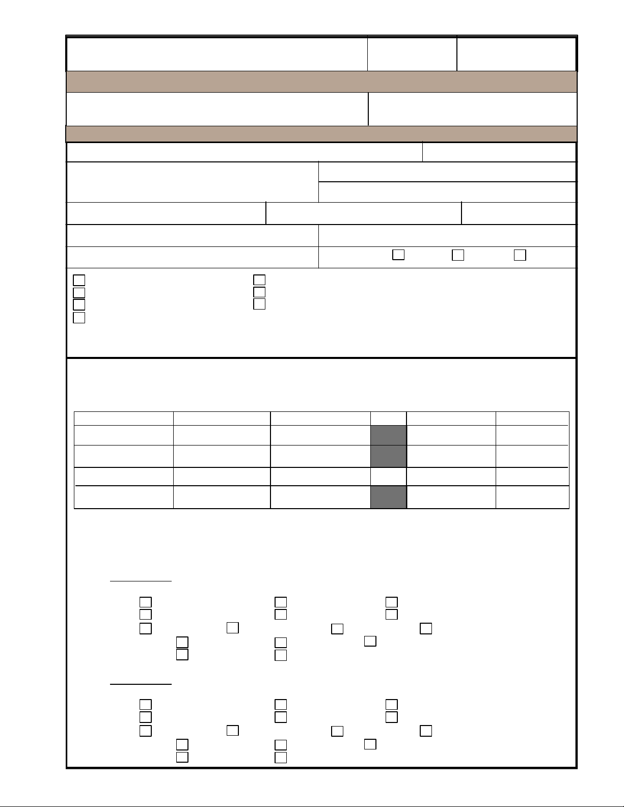
Purpose: Quality Assurance Testing
Customer Name:
Address: System Model:
System Serial #:
System ID #:
Purchase Order #:
System Configuration
Video Cassette Recorder
Line Printer
Video Page Printer
Urological Therapy Guidance
Other ___________________________________
_________________________________________
Field Service Engineer: ____________________________________ Employee #: _______________
US Unit Manufacturer:
Dispatch #:
System Status: Warranty Contract Billable
Biopsy Guide
Spectral Doppler
Color
Configuration Notes:
Refer to the Ultrasound QA Reference
Manual 2262684-100 for details.
Survey Date:
Year of Mfg.:
TEST EQUIPMENT
NAME MANUFACTURER MODEL Atten. SERIAL # CAL DATE
Leakage Tester
Multimeter
Gray Scale Phantom
TRANSDUCERS TESTED
The two transducers used most frequently should be listed as transducer number 1 and 2. Use the
separate documents provided to document the remaining transducers.
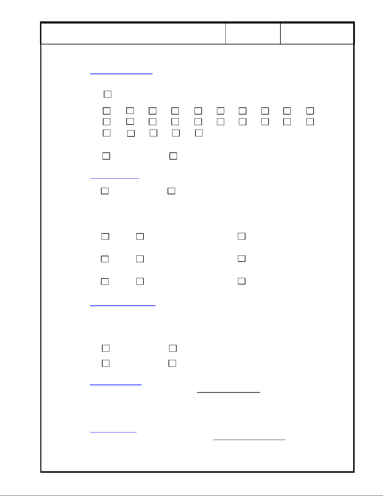
Transducer 1
Model: ________________________ Serial Number: ______________________________
Type: General Purpose Superficial Intraoperative
Endorectal Endovaginal Other _____________________
Freq: 2-3.5 MHz 3-5 MHz 5-7.5 MHz 7.5 MHz and higher
Scan Format: Phased Array Linear Array Curved Linear Array
Transducer 2
Model: ________________________ Serial Number: ______________________________
Type: General Purpose Superficial Intraoperative
Endorectal Endovaginal Other _____________________
Freq: 2-3.5 MHz 3-5 MHz 5-7.5 MHz 7.5 MHz and higher
Scan Format: Phased Array Linear Array Curved Linear Array
Mechanical Other _____________________
Mechanical Other _____________________
Page 12
g
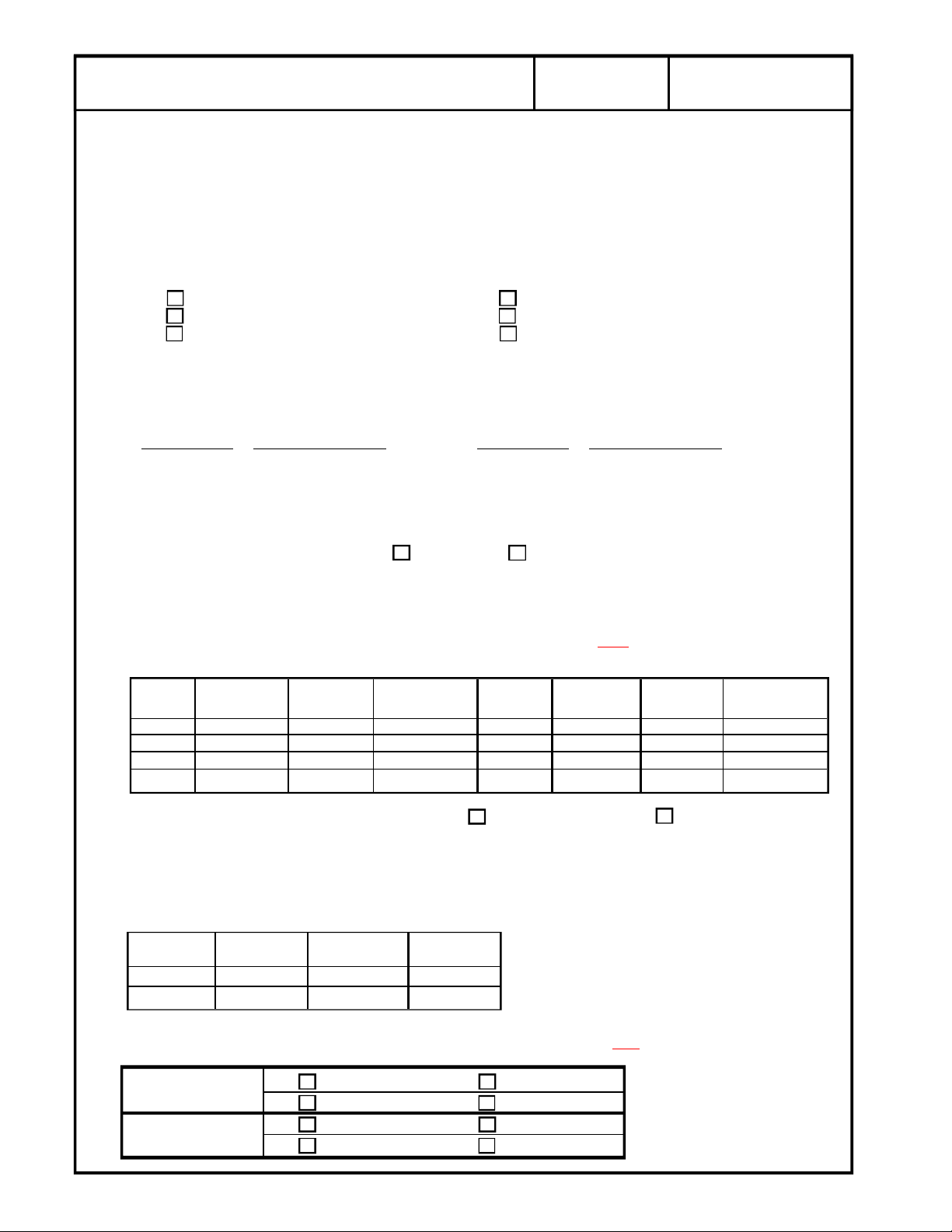
LINE VOLTAGE TEST
System OFF: ______________VAC__ System ON: ________________VAC__
LINE CURRENT TEST (optional)
System OFF: ______________Amps_ System ON: ________________Amps_
OUTLET WIRING TEST QA Reference Manual Section 3-3. If correct, proceed to the next step.
GROUND CONTINUITY
QA Reference Manual Section 3-4. Use the Dale 600 Tester. Resistance should be less than 0.2
Ohms. If greater than 0.2 Ohms, perform detailed chassis leakage tests and troubleshoot.
GE Medical Systems
Correct Wiring Open Ground Wire
Reversed Polarity Open Neutral Wire
Hot & Gnd Reversed Open Hot Wire
2/16
2277615-100
REV 0
TEST POINT
Console _______________ Probe Screw ______________(any side screw)
Caster _______________ Foot Switch ________________
Monitor _______________ Printer ________________
Ground Continuity Tests PASS FAIL
CHASSIS SOURCE LEAKAGE TEST
QA Reference Manual Section 3-5. Max allowable is 300 uA.
IMPORTANT: Be sure to pause the polarity reverse switch in the OFF
seconds before reversing polarity.
POWER POLARITY SWITCH CHASSIS GND POWER POLARITY SWITCH CHASSIS GND
ON NORM Closed ON REV Closed
ON NORM Open ON REV Open
OFF NORM Closed OFF REV Closed
OFF NORM Open OFF REV Open
Chassis Source Leakage Tests Summary PASS FAIL
TRANSDUCER LEAKAGE CURRENT TESTS
All readings in micro-amps. Maximum allowable leakage current is 100 uA for general purpose and
endocavitary or 50 uA for surgical probes. QA Reference Manual Section 3-9.
DALE 600 DALE 600
POLARITY GND SW PROBE 1 PROBE 2
NORM Closed
NORM Open
Resistance (ohms) TEST POINT Resistance (ohms)
GROUND CONSOLE GROUND CONSOLE
VCR ________________
position for a minimum of 10
Transducer Leakage Current Test Summary: Choose Pass or Fail and
Transducer 1 PASS FAIL
CHANGE NO CHANGE
Transducer 2 PASS FAIL
CHANGE NO CHANGE
Change or No Change
Page 13
g
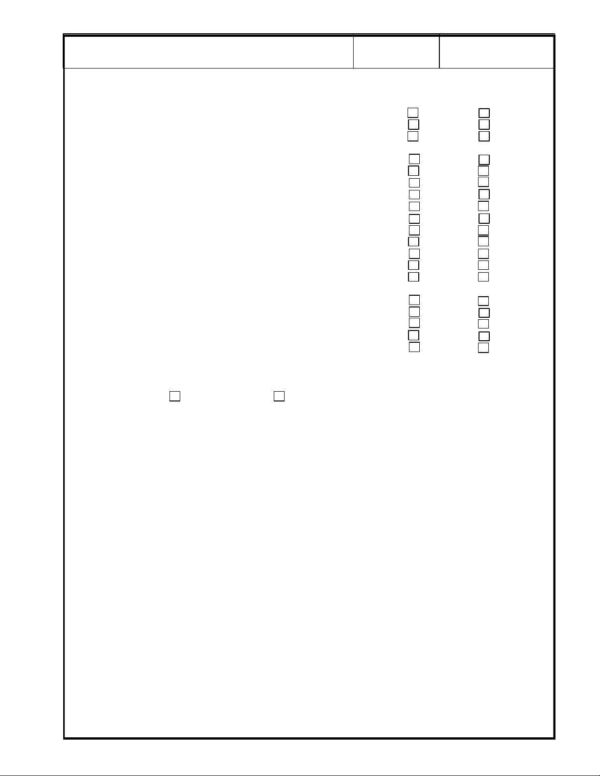
PHYSICAL INSPECTION/CLEANING
Cleaned and inspected the console? YES NO
Cleaned and inspected foot switch? YES NO
All cords and cables intact (no frays, tears or splits)? YES NO
All transducers intact
All transducer connector pins straight and intact? YES NO
All transducer strain reliefs in good condition? YES NO
All transducers cleaned (after each use)? YES NO
Image monitors cleaned? YES NO
Cleaned and inspected all power supplies? YES NO
All fans and/or air filters cleaned? YES NO
Checked all cable connectors to ensure they are properly seated? YES NO
Checked all plug-in boards to ensure they are properly seated? YES NO
All wheel locks in working condition? YES NO
All wheels fastened securely? Do they rotate easily? YES NO
All "onboard" peripherals fastened securely
Cleaned thermal printer print head with cleaner paper? YES NO
GE Medical Systems
(no cracks, dents, scratches or delamination)? YES NO
to the ultrasound unit (VCRs, Cameras, Printers, etc....)? YES NO
3/16
VCR Inspected Cleaned
Printer Inspected Cleaned
Camera Inspected Cleaned
REV 0
2277615-100
Overall Electrical Safety and Cleanliness:
CHANGE NO CHANGE
All safety problems must be rectified before the system can be returned to service or before ACR
Accreditation submittal.
Comments: _____________________________________________________________________
_______________________________________________________________________________
_______________________________________________________________________________
_______________________________________________________________________________
_______________________________________________________________________________
_______________________________________________________________________________
_______________________________________________________________________________
_______________________________________________________________________________
_______________________________________________________________________________
_______________________________________________________________________________
_______________________________________________________________________________
_______________________________________________________________________________
_______________________________________________________________________________
Page 14
g
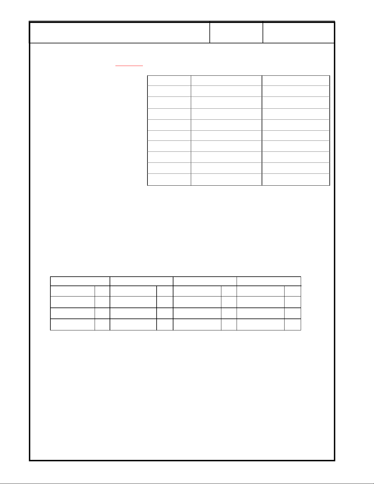
Power Supply Readings Refer to Chapter 4, Section 4-3 of the LOGIQ a200 or LOGIQ 200 PRO Service
Manuals for details on tolerances
Power Supplies available
depend on the type of system
serviced.
GE Medical Systems
, checking and adjusting of power supplies.
Supply Actual Reading Adjusted To
+5v Digital
-5v Digital
4/16
REV 0
2277615-100
Check only those that apply.
Mark all other entries N/A.
Reference is 0 voltage for the supply being measured.
Comments: ____________________________________________________________________
_______________________________________________________________________________
_______________________________________________________________________________
Functional Checks Refer to Chapter 4, Section 4-2 of the LOGIQ a200 or LOGIQ 200 PRO Service Manual.
General B-Mode B/M-Mode M-Mode
+5v Analog
-5 v Analog
+15
-15
+12v
-12v
HV
Foot Switch Focus Oper. Focus Oper. Focus Oper.
Record Key Gain Knob Gain Knob Gain Knob
Freeze Key TGC Pots TGC Pots TGC Pots
Printer Setting Dynamic Range Dynamic Range Dynamic Range
Comments: _____________________________________________________________________
_______________________________________________________________________________
_______________________________________________________________________________
NOTE: Refer to the LOGIQ a200 or LOGIQ 200 PRO User Manual for more information on system operation.
Page 15
g
GRAY SCALE TEST
Refer toChapter 2, Section 2-3-2 in the LOGIQ a200 or LOGIQ 200PRO Proprietary manual for details on
entering the service software program, tests and control commands.
GE Medical Systems
5/16
2277615-100
REV 0
Select Monitor Test
The gray scale test is not intended to set up the camera, printer or peripherals to the test pattern. Ensure
that the monitor and photography are set up to the customer specifications.
Look at the gray bar test pattern on the left side of the viewing monitor.
Count the number of distinct gray bar steps on the viewing monitor. Then count the number of steps
visualized in the Gray bar on the hard copy image. Circle the number of steps, if any, that are missing on
the hard copy. Circle the number of steps, if any, that are missing on the hard copy.
Check the one box that applies:
Number of steps missing on the hard copy: 0 1 2 3 4+
Has the photography changed since the last QA Test?
NOTE: Press <CTRL><X> to exit the Monitor Test
from the Service Utility Menu
Change No Change (or First Test)
SECURE PAGE PRINT OF GRAY SCALE TEST HERE
Page 16
g
OVERVIEW
The following tests should be performed with each probe. Where indicated, a hard copy record should
be made and filed in order to assess performance trending during subsequent QA checks.
Refer to the QA Procedures Reference Manual for details in performing any tests.
GE Medical Systems
6/16
PERFORMANCE EVALUATION TESTS
2277615-100
REV 0
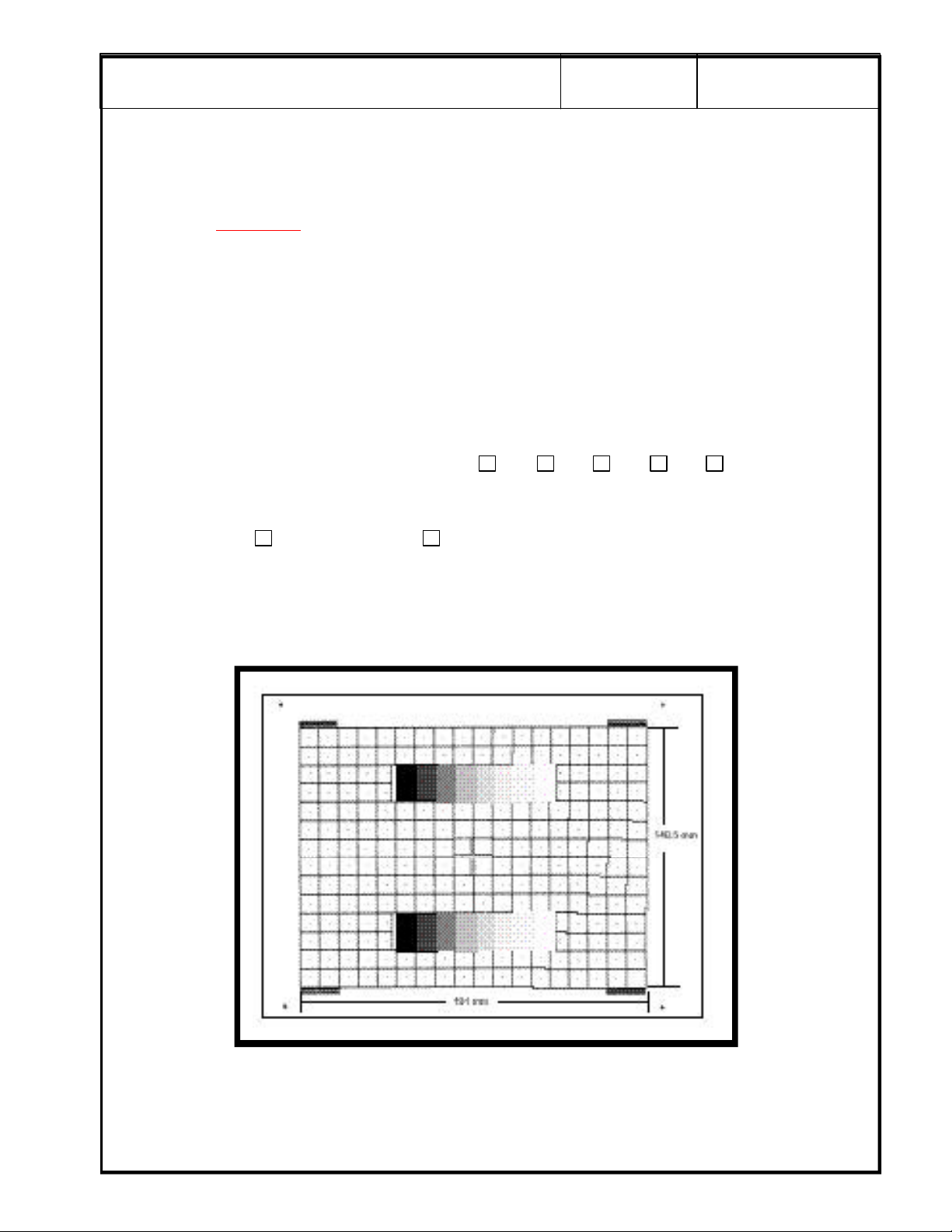
PHANTOM
.
Temperature __________________________
* Remember that phantom temperature may demonstrate errors in excess of 10% if you are establishing
a baseline or comparing to previous results.
Probe 1:
For Probe 1, adjust the system settings to produce the best possible overall image of the phantom.
This scan will be used to assess penetration capabilities, image uniformity, measurement
accuracy, axial resolution, lateral resolution and contrast detectability.
Gain: ________________________ Focus : ________________________
Dynamic Range: ____________________
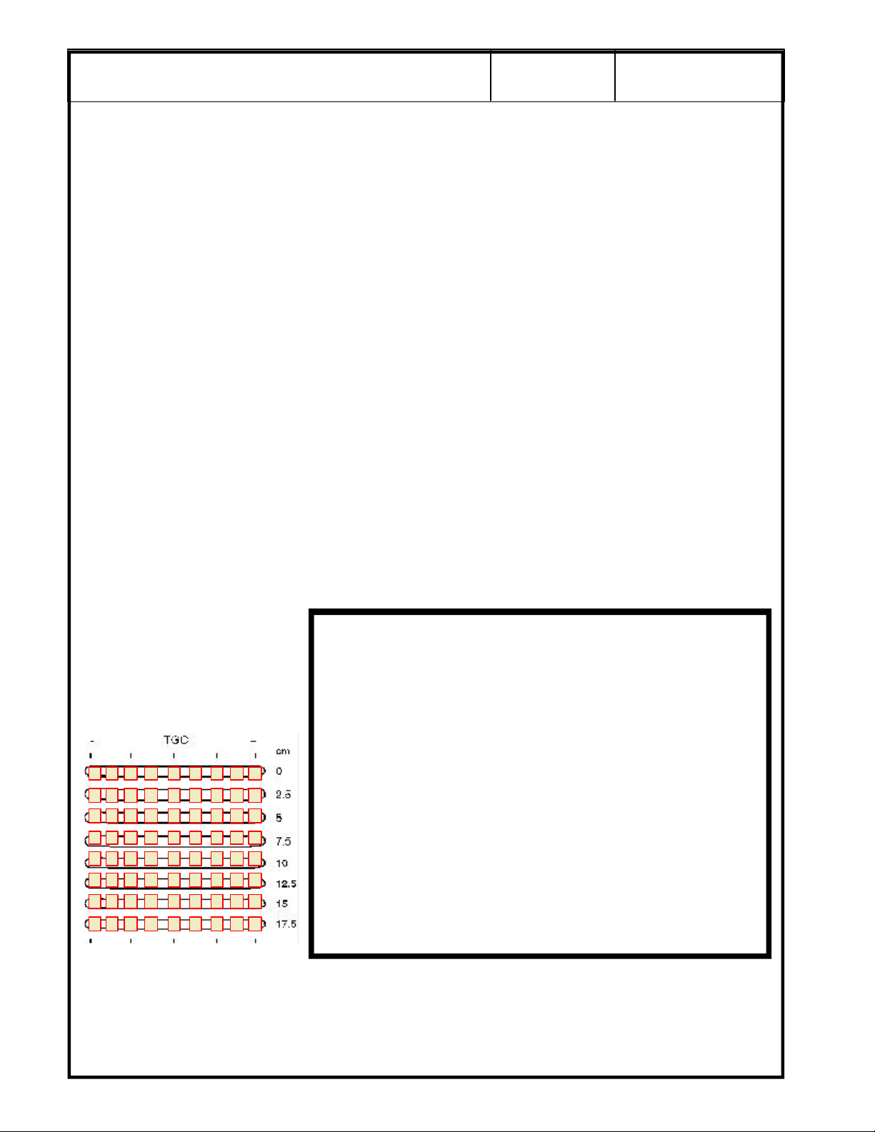
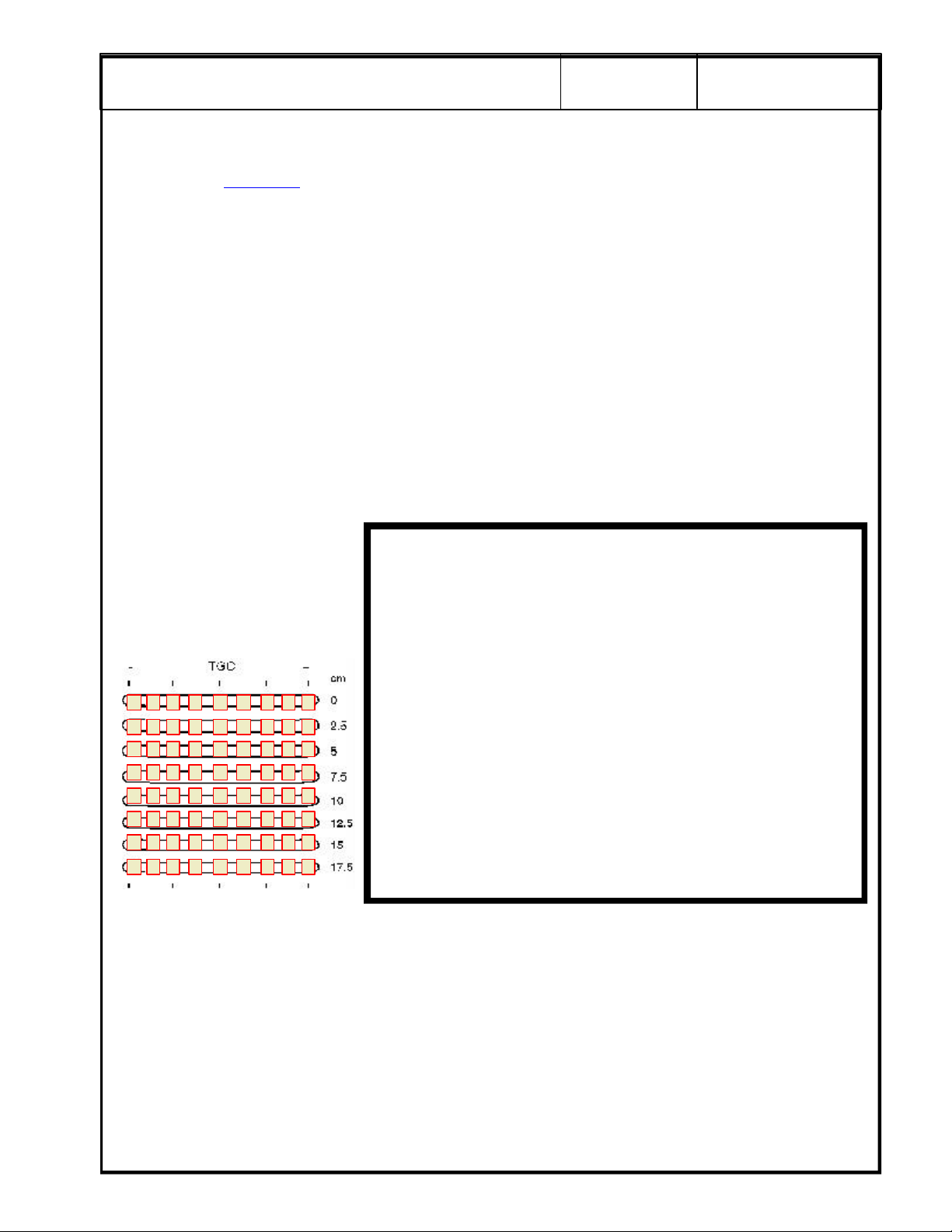
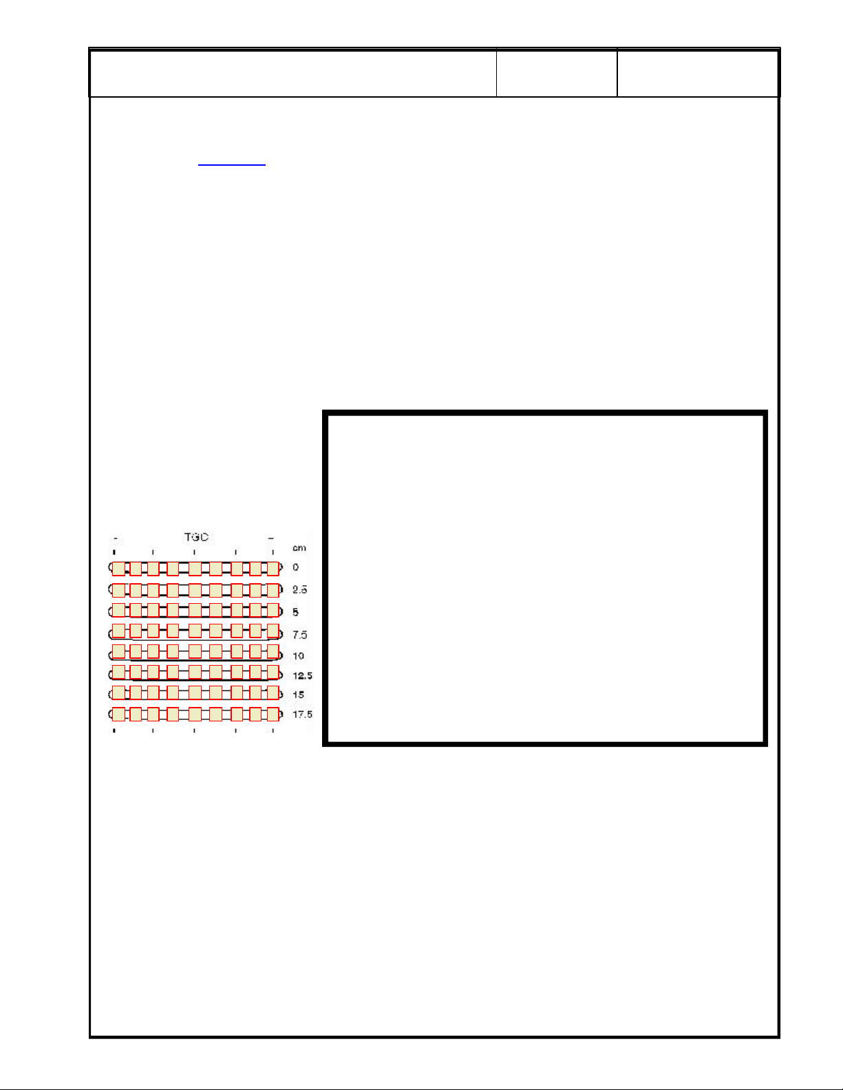
For scan repeatability during
the next QA check, place a
check mark in a box to
indicate the relative position of
each TCG control for the scan.
SECURE PAGE PRINT OF PROBE 1 SCAN
Page 17
g
Probe 1 (cont'd):
GE Medical Systems
7/16
2277615-100
REV 0
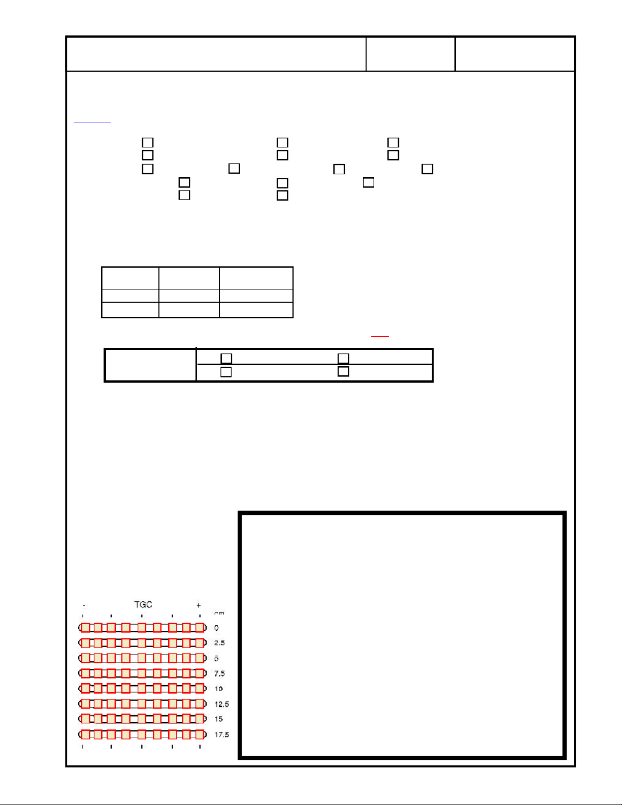
Penetration Capability
from the skin line to the point furthermost in depth where echoes disappear and record the depth
in centimeters. The maximum depth through which the echographic pattern can be visualized
is: Less than 3.0
3.0 3.5 4.0 4.5 5.0 5.5 6.0 6.5 7.0 7.5
8.0 8.5 9.0 9.5 10.0 10.5 11.0 11.5 12.0 12.5
13.0 13.5 14.0 15.0 116.0 or higher
Did system penetration change since the previous test?
Change No Change ( or First Test)
Image Uniformity
Change No Change (or First Test)
With your eye, evaluate the scan for image uniformity against the three indicators below:
The average brightness at the edge of the scan is the same as the average brightness in the
middle.
Agree Disagree, slight non-uniformity Disagree, major non-uniformity
There are no vertical or radially oriented shadows from array element dropout.
Agree Disagree, slight non-uniformity Disagree, major non-uniformity
. QA Reference Manual Section 4-2 Step 4. Use the calipers to measure
. Assess the image for uniformity from near field to far field.
There are no noticeable brightness transitions between focal zones.
Agree Disagree, slight non-uniformity Disagree, major non-uniformity
Measurement Accuracy
from the vertical pin closest to the skin line to the pin furthermost in depth. Do the same with
the horizontal row of pins.
Did the distance between the pins measured equal the e-caliper measurement?
Pass Fail
Change No Change (or First Test)
Lateral Resolution
how well the system/probe can display two targets side by side
of two targets on the same horizontal plane is the Lateral Resolution.
Note the Lateral Resolution measurement in mm : ________________________________
Axial Resolution
well the system/probe can display two targets above and below each other
distance of two targets on the same vertical plane is the Axial resolution.
. QA Reference Manual Section 4-2 Step 2. AXIAL resolution defines how
. QA Reference Manual Section 4-2 Step 3. Use the calipers to measure
. QA Reference Manual Section 4-2 Step 1. LATERAL resolution defines
. The smallest visible distance
. The smallest visible
Note the Axial Resolution measurement in mm : ________________________________
Page 18
g
NO
NO
NO
NO
NO
Probe 1 (cont'd):
GE Medical Systems
8/16
2277615-100
REV 0
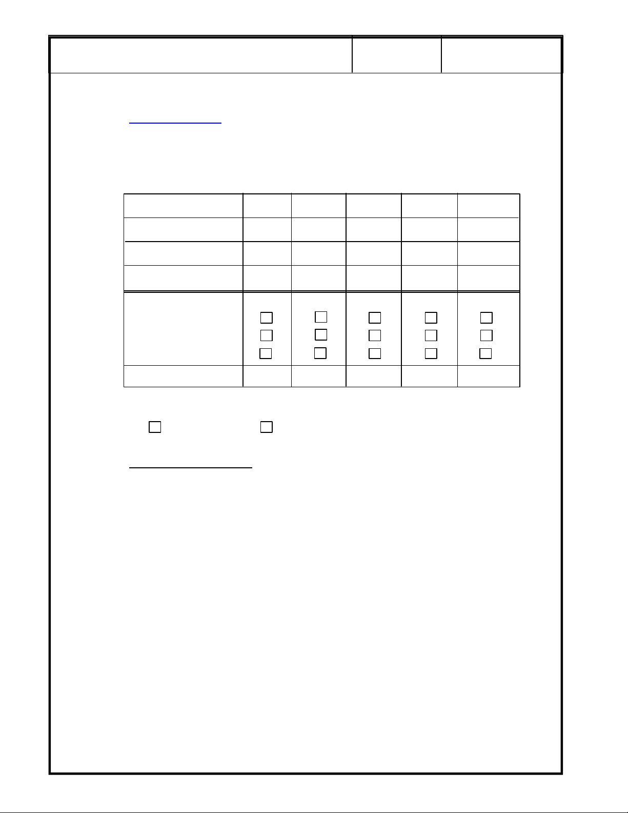
Contrast Resolution
the phantom contrast targets in the current scan. The point is not how any ONE of the targets
look but how well defined they are from each other, and from the background material.
Record the following information for five of the contrast targets, if available in the phantom. If
they are not available, indicate with N/A:
Object Number 1 2 3 4 5
Object Depth
Object Size
Object Contrast *
Object Detectability
Complete
Partial
Not Seen
Changed for Worse Y/N
Overall Probe Low Contrast Detectability:
Change No Change (or First Test)
. (OPTIONAL) QA Reference Manual Section 4-2 Step 6 & 7. Evaluate
Notes for contrast resolution
Object Depth - is from the skin line to the center of the object.
Object Size - is the overall diameter of the object (all should be the same)
Object Contrast -
Use the Echo Level function by freezing the image. Press the Measurement
key three (3) times to assess the gray scale contrast level.
A 3 cm square box appears in the image area.
Position the box in the center of the contrast object.
Press Set.
Record the resulting number as the Object Contrast in the chart above.
Object Detectability - Check one box according to your evaluation of the object.
Changed for Worse Y/N - Enter a Y (yes) or N (no).
Document any system setting changes if they are different than the original scan on page 6.
_____________________________________________________________________________
_____________________________________________________________________________
_____________________________________________________________________________
:
Page 19
g
Probe 1 (cont'd):
GE Medical Systems
9/16
2277615-100
REV 0
Noise Level
scanning conditions. Describe the lighting conditions for repeatability during the next QA check.
___________________________________________________________________________________________________________
Adjust the system settings to produces a clean image.
Wipe all the gel from the probe face, and set the probe in its holder. With transmit power at a
fixed value, adjust the overall gain, until the far field image (beyond 3cm) begins to fill with noise.
Reduce the overall gain until the last of those noise “speckles” disappear.
Note the gain level on film and make a hard copy record of this test.
Gain: ________________________ Focus : ________________________
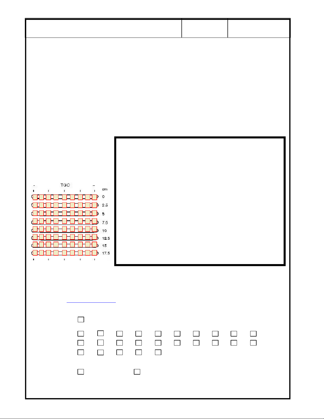
For scan repeatability during
the next QA check, place a
check mark in a box to
indicate the relative position of
each TCG control for the scan.
. QA Reference Manual Section 4-2 Step 5. Ensure that room lighting is set to normal
SECURE PAGE PRINT OF
PROBE 1 NOISE LEVEL
SCAN HERE
Page 20
g
Probe 2:
For scan repeatability during
the next QA check, place a
check mark in a box to
indicate the relative position of
each TCG control for the scan.
GE Medical Systems
For Probe 2, adjust the system settings to produce the best possible overall image of the phantom.
This scan will be used to assess penetration capabilities, image uniformity, measurement
accuracy, axial resolution, lateral resolution and contrast detectability.
Gain: ________________________ Focus : ________________________
Dynamic Range: ____________________
10/16
2277615-100
REV 0
SECURE PAGE PRINT OF PROBE 2 SCAN
Penetration Capability
from the skin line to the point furthermost in depth where echoes disappear and record the depth
in centimeters. The maximum depth through which the echographic pattern can be visualized
is: Less than 3.0
3.0 3.5 4.0 4.5 5.0 5.5 6.0 6.5 7.0 7.5
. QA Reference Manual Section 4-2 Step 4. Use the calipers to measure
8.0 8.5 9.0 9.5 10.0 10.5 11.0 11.5 12.0 12.5
13.0 13.5 14.0 15.0 16.0 or higher
Did system penetration change since the previous test?
Change No Change ( or First Test)
Page 21
g
Probe 2 (cont'd):
GE Medical Systems
11/16
2277615-100
REV 0
Image Uniformity
Change No Change (or First Test)
With your eye, evaluate the scan for image uniformity against the three indicators below:
The average brightness at the edge of the scan is the same as the average brightness in the
middle.
Agree Disagree, slight non-uniformity Disagree, major non-uniformity
There are no vertical or radially oriented shadows from array element dropout.
Agree Disagree, slight non-uniformity Disagree, major non-uniformity
There are no noticeable brightness transitions between focal zones.
Agree Disagree, slight non-uniformity Disagree, major non-uniformity
Measurement Accuracy
from the vertical pin closest to the skin line to the pin furthermost in depth. Do the same with
the horizontal row of pins.
Did the distance between the pins measured equal the e-caliper measurement?
Pass Fail
. Assess the image for uniformity from near field to far field.
. QA Reference Manual Section 4-2 Step 3. Use the calipers to measure
Change No Change (or First Test)
Lateral Resolution
how well the system/probe can display two targets side by side
of two targets on the same horizontal plane is the Lateral Resolution.
Note the Lateral Resolution measurement in mm : ________________________________
Axial Resolution
the system/probe can display two targets above and below each other
of two targets on the same vertical plane is the Axial resolution.
Note the Axial Resolution measurement in mm : ________________________________
. QA Reference Manual Section 4-2 Step 1. LATERAL resolution defines
. The smallest visible distance
. QA Reference Manual Section 4-2 Step 2. AXIAL resolution defines how well
. The smallest visible distance
Page 22
g
NO
NO
NO
NO
NO
Probe 2 (cont'd):
GE Medical Systems
12/16
2277615-100
REV 0
Contrast Resolution
the phantom contrast targets in the current scan. The point is not how any ONE of the targets
look but how well defined they are from each other, and from the background material.
Record the following information for five of the contrast targets, if available in the phantom. If
they are not available, indicate with N/A:
Object Number 1 2 3 4 5
Object Depth
Object Size
Object Contrast *
Object Detectability
Complete
Partial
Not Seen
Changed for Worse Y/N
Overall Probe Low Contrast Detectability:
Change No Change (or First Test)
. (OPTIONAL) QA Reference Manual Section 4-2 Step 6 & 7. Evaluate
Notes for contrast resolution
Object Depth - is from the skin line to the center of the object.
Object Size - is the overalldiameter of the object (all should be the same)
Object Contrast -
Use the Echo Level function by freezing the image. Press the Measurement
key three (3) times to assess the gray scale contrast level.
A 3 cm square box appears in the image area.
Position the box in the center of the contrast object.
Press Set.
Record the resulting number as the Object Contrast in the chart above.
Object Detectability - Check one box according to your evaluation of the object.
Changed for Worse Y/N - Enter a Y (yes) or N (no).
Document any system setting changes if they are different than the original scan on page 6.
_____________________________________________________________________________
_____________________________________________________________________________
_____________________________________________________________________________
:
Page 23
g
Probe 2 (cont'd):
GE Medical Systems
13/16
2277615-100
REV 0
Noise Level
scanning conditions. Describe the lighting conditions for repeatability during the next QA check.
___________________________________________________________________________________________________________
Adjust the system settings to produces a clean image.
Wipe all the gel from the probe face, and set the probe in its holder. With transmit power at a
fixed value, adjust the overall gain, until the far field image (beyond 3cm) begins to fill with noise.
Reduce the overall gain until the last of those noise “speckles” disappear.
Note the gain level on film and make a hard copy record of this test.
Gain: ________________________ Focus : ________________________
For scan repeatability during
the next QA check, place a
check mark in a box to
indicate the relative position of
each TCG control for the scan.
. QA Reference Manual Section 4-2 Step 5. Ensure that room lighting is set to normal
Customer Acceptance and Sign-off
Assure covers and side panels are aligned and secure.
Reconnect any peripherals and interconnections removed during the QA Tests.
Return the system to it's original location, if moved.
Refer to the QA Reference Manual Section 2-15.
Gain Customer acceptance that the system is ready to return to service.
______________________________________________ _____________
Customer Signature Date
SECURE PAGE PRINT OF
PROBE 2 NOISE LEVEL
SCAN HERE
______________________________________________ _____________
Field Engineer Signature Date
Page 24

g
GE Medical Systems
14/16
REV 0
OPTIONAL DATA FOR THE LOGIQ α200 OR LOGIQ 200 PRO
2277615-100
The remainder of the checks are optional steps that can be accomplished by the field engineer or the customer.
While the following do not directly affect image quality, it may be good information to archive in the event that
the system would need to be restored after a catastrophic system failure.
LOGIQ 200 PRO
PRESETS
All system presets can be saved on a 128 Mbyte MOD through the SETUP>UTILITY Menu.
Press the SETUP MENU Key. Arrow down to USER UTILITY and press SET.
In the USER UTILITY Menu, ensure that a MOD has been formatted using Media Initialize.
Perform thye following procedures:
Preset Data Backup
OB User Table Backup
OB Trend Data Backup.
Label and date the MOD accordingly and have the customer store it in a safe place.
Preset data backed up at the request of the customer.
Customer chose not to back up preset data.
Page 25
g
This process is more intensive than a LOGIQ 200 PRO. No device is available the save the presets
electronically. Each screen must be displayed on the monitor and a print taken of that display. The prints
can then be stored in a safe place for future reference.
Ask the customer which menus are important for them to archive in the rare case of a catastropic failure.
PRESETS
To go directly to the system setup parameters pages, press <CTRL><S>
Make prints of all System Setup Parameter pages.
Remember: Some pages may require two or more prints due to each applications presets and then for
each probe attached. Use the following items as a check list of what menus were printed:
GE Medical Systems
LOGIQ α200
General System Setup
User OB Table Sub menu
Probe Parameter 1 Setup
Preset 1
Probe 1
Probe 2
Preset 2
Probe 1
Probe 2
Probe Parameter 2 Setup
Preset 1
Probe 1
Probe 2
Preset 2
Probe 1
Probe 2
Image Display and Application Setup
Preset 1
Preset 2
Body Pattern Setup
Preset 1
Preset 2
Comment Setup
Preset 1
Preset 2
Measurement Setup
Preset 1
Report Format Sub menu
A/N Assignment Sub menu
Cardiac Calc Sub menu
Preset 2
Report Format Sub menu
A/N Assignment Sub menu
Cardiac Calc Sub menu
Patient Entry Setup
Preset 1
Preset 2
15/16
2277615-100
REV 0
Page 26

g
Yes
Yes
Yes
Yes
Yes
Yes
Yes
Yes
Yes
Yes
Yes
Yes
Yes
Yes
Yes
Yes
Yes
Yes
Yes
Yes
Yes
Yes
Yes
Yes
Yes
Yes
Yes
Yes
Yes
Diagnostics Refer toChapter 2, Section 2-3-2 in the LOGIQ a200 or LOGIQ 200PRO Proprietary manual for
details on entering the service software program, tests and control commands.
Caution: If you perform the over all System Test it will run for 21 minutes.
LOGIQ a200 Pass? LOGIQ 200 PRO Pass?
Beamformer Scan Test
HV TBF
ADC Linear/Convex Path
DSC/Front End Function Sector Path
B-Mode Function BPHV
B-Mode X-Y Memory MVP Hardware
B-Mode Cine B-Mode Function
M-Mode Function B-Mode Cine
MST M-Mode Function
System D-RAM MSTE
Keyboard Keyboard
PIOP PIOP
Monitor Monitor
Power Supply Power Supply
ROM Version
GE Medical Systems
16/16
REV 0
2277615-100
Comments: _____________________________________________________________________
_______________________________________________________________________________
_______________________________________________________________________________
Page 27

05/23/00 MAC
LOGIQ a200 and LOGIQ 200 PRO
ACR Accredited Quality Assurance Procedure
Probe ID List
Name Model # Type Frequency Scan Format
CBF H460222CB Gen Purp 3-5 MHz Curved Linear
CAE H46022CA Gen Purp 5-7.5 MHz Curved Linear
MTZ H46022MT Endo Vag 5-7.5 MHz Curved Linear
CZB H45202CZ Superficial 5-7.5 MHz Curved Linear
CS H45222CS Gen Purp 3-5 MHz Curved Linear
ERB H45202ER Endorectal 5-7.5 MHz Curved Linear
3Cb H45202WB Gen Purp 3-5 MHz Curved Linear
LH H46022LH Superficial 7.5 MHz + Linear
LE H46022LE Gen Purp 5-7.5 MHz Linear
LI H46022LI Intraoperative 7.5 MHz + Linear
LT H46022LT Intraoperative 7.5 MHz + Linear
LB H46022LB Gen Purp 3-5 MHz Linear
LD H45202LD Intraoperative 3-5 MHz Linear
10L H45202LM Gen Purp 5-7.5 MHz Linear
SY H46022SY Gen Purp 3-5 MHz Phased Array
S317 H45202SD Gen Purp 3-5 MHz Phased Array
ATR H4061PR Endorectal 5-7.5 MHZ Curved Linear
Page 1 of 2
Page 28

05/23/00 MAC
Page 2 of 2
Page 29
g
GE Medical Systems
PERFORMANCE EVALUATION
Probe 3
Model: ________________________ Serial Number: ______________________________
Type: General Purpose Superficial Intraoperative
Endorectal Endovaginal Other _____________________
Freq: 2-3.5 MHz 3-5 MHz 5-7.5 MHz 7.5 MHz and higher
Scan Format: Phased Array Linear Array Curved Linear Array
Mechanical Other _____________________
TRANSDUCER LEAKAGE CURRENT TESTS
All readings in micro-amps. Maximum allowable leakage current is 100 uA for general purpose and
endocavitary or 50 uA for surgical probes. QA Reference Manual Section 3-9.
DALE 600 DALE 600
POLARITY GND SW PROBE 3
NORM Closed
NORM Open
Leakage Current Test Summary: Choose Pass or Fail and Change or No Change
1/4
2267008-100
REV 0
Probe 3 PASS FAIL
CHANGE NO CHANGE
For Probe 3, adjust the system settings to produce the best possible overall image of the phantom. This
scan will be used to assess penetration capabilities, image uniformity, measurement accuracy, axial
resolution, lateral resolution and contrast detectability.
Gain: ________________________ Focus : ________________________
Dynamic Range: ____________________
For scan repeatability during
the next QA check, place a
check mark in a box to indicate
the relative position of each
TCG control for the scan.
SECURE PAGE PRINT OF PROBE SCAN
Page 30
g
Probe 3 (cont'd):
GE Medical Systems
Penetration Capability. QA Reference Manual Section 4-2 Step 4. Use the calipers to measure
from the skin line to the point furthermost in depth where echoes disappear and record the depth
in centimeters. The maximum depth through which the echographic pattern can be visualized is:
Less Than 3.0
3.0 3.5 4.0 4.5 5.0 5.5 6.0 6.5 7.0 7.5
8.0 8.5 9.0 9.5 10.0 10.5 11.0 11.5 12.0 12.5
13.0 13.5 14.0 15.0 16.0 or higher
Did system penetration change since the previous test?
Change No Change ( or First Test)
Image Uniformity. Assess the image for uniformity from near field to far field.
Change No Change (or First Test)
With your eye, evaluate the scan for image uniformity against the three indicators below:
2/4
2267008-100
REV 0
The average brightness at the edge of the scan is the same as the average brightness in the
middle.
Agree Disagree, slight non-uniformity Disagree, major non-uniformity
There are no vertical or radially oriented shadows from array element dropout.
Agree Disagree, slight non-uniformity Disagree, major non-uniformity
There are no noticeable brightness transitions between focal zones.
Agree Disagree, slight non-uniformity Disagree, major non-uniformity
Measurement Accuracy. QA Reference Manual Section 4-2 Step 3. Use the calipers to measure
from the vertical pin closest to the skin line to the pin furthermost in depth. Do the same with the
horizontal row of pins.
Did the distance between the pins measured equal the e-caliper measurement?
Pass Fail
Change No Change (or First Test)
Lateral Resolution. QA Reference Manual Section 4-2 Step 1. LATERAL resolution defines
how well the system/probe can display two targets side by side. The smallest visible distance of
two targets on the same horizontal plane is the Lateral Resolution.
Note the Lateral Resolution measurement in mm : ________________________________
Axial Resolution. QA Reference Manual Section 4-2 Step 2. AXIAL resolution defines how well
the system/probe can display two targets above and below each other. The smallest visible distance
of two targets on the same vertical plane is the Axial resolution.
Note the Axial Resolution measurement in mm : ________________________________
Page 31

g
NO
NO
NO
NO
NO
Probe 3 (cont'd):
GE Medical Systems
3/4
2267008-100
REV 0
Contrast Resolution
the phantom contrast targets in the current scan. The point is not how any ONE of the targets look
but how well defined they are from each other, and from the background material.
Record the following information for five of the contrast targets, if available in the phantom. If they
are not available, indicate with N/A:
Object Number 1 2 3 4 5
Object Depth
Object Size
Object Contrast *
Object Detectability
Complete
Partial
Not Seen
Changed for Worse Y/N
Overall Probe Low Contarst Detectability
Change No Change (or First Test)
. (OPTIONAL) QA Reference Manual Section 4-2 Step 6 & 7. Evaluate
Notes for contrast resolution
Object Depth - is from the skin line to the center of the object.
Object Size - is the overalldiameter of the object (all should be the same)
Object Contrast -
Use the Echo Level function by Freezing the image. Press the Measurement
key three (3) times to assess the gray scale contrast level.
A 3 cm square box appears in the image area.
Position the box in the center of the contrast object.
Press Set.
Record the resulting number as the Object Contrast in the chart above.
Object Detectability - Check one box according to your evaluation of the object.
Changed for Worse Y/N - Enter a Y (yes) or N (no).
Document any system setting changes if they are different than the original scan on page 6.
_____________________________________________________________________________
_____________________________________________________________________________
_____________________________________________________________________________
:
Page 32

g
Probe 3 (cont'd):
GE Medical Systems
Noise Level. QA Reference Manual Section 4-2 Step 5. Ensure that room lighting is set to normal
scanning conditions. Describe the lighting conditions for repeatability during the next QA check.
___________________________________________________________________________________________________________
Adjust the system settings to produces a clean image.
Wipe all the gel from the probe face, and set the probe in its holder. With transmit power at a fixed
value, adjust the overall gain, until the far field image (beyond 3cm) begins to fill with noise. Reduce
the overall gain until the last of those noise “speckles” disappear.
Note the gain level on film and make a hard copy record of this test.
Gain: ________________________ Focus : ________________________
4/4
2267008-100
REV 0
For scan repeatability during
the next QA check, place a
check mark in a box to indicate
the relative position of each
TCG control for the scan.
SECURE PAGE PRINT OF
PROBE NOISE LEVEL
SCAN HERE
Page 33

g
GE Medical Systems
PERFORMANCE EVALUATION
Probe 4
Model: ________________________ Serial Number: ______________________________
Type: General Purpose Superficial Intraoperative
Endorectal Endovaginal Other _____________________
Freq: 2-3.5 MHz 3-5 MHz 5-7.5 MHz 7.5 MHz and higher
Scan Format: Phased Array Linear Array Curved Linear Array
Mechanical Other _____________________
TRANSDUCER LEAKAGE CURRENT TESTS
All readings in micro-amps. Maximum allowable leakage current is 100 uA for general purpose and
endocavitary or 50 uA for surgical probes. QA Reference Manual Section 3-9.
DALE 600 DALE 600
POLARITY GND SW PROBE 3
NORM Closed
NORM Open
1/4
2272728-100
REV 0
Leakage Current Test Summary: Choose Pass or Fail and
Probe 4 PASS FAIL
CHANGE NO CHANGE
For Probe 3, adjust the system settings to produce the best possible overall image of the phantom. This
scan will be used to assess penetration capabilities, image uniformity, measurement accuracy, axial
resolution, lateral resolution and contrast detectability.
Gain: ________________________ Focus : ________________________
Dynamic Range: ____________________
For scan repeatability during
the next QA check, place a
check mark in a box to indicate
the relative position of each
TCG control for the scan.
SECURE PAGE PRINT OF PROBE SCAN
Change or No Change
Page 34

g
Probe 4 (cont'd):
GE Medical Systems
2/4
2272728-100
REV 0
Penetration Capability
from the skin line to the point furthermost in depth where echoes disappear and record the depth
in centimeters. The maximum depth through which the echographic pattern can be visualized is:
Less Than 3.0
3.0 3.5 4.0 4.5 5.0 5.5 6.0 6.5 7.0 7.5
8.0 8.5 9.0 9.5 10.0 10.5 11.0 11.5 12.0 12.5
13.0 13.5 14.0 15.0 16.0 or higher
Did system penetration change since the previous test?
Change No Change ( or First Test)
Image Uniformity
Change No Change (or First Test)
With your eye, evaluate the scan for image uniformity against the three indicators below:
The average brightness at the edge of the scan is the same as the average brightness in the
middle.
Agree Disagree, slight non-uniformity Disagree, major non-uniformity
There are no vertical or radially oriented shadows from array element dropout.
Agree Disagree, slight non-uniformity Disagree, major non-uniformity
. QA Reference Manual Section 4-2 Step 4. Use the calipers to measure
. Assess the image for uniformity from near field to far field.
There are no noticeable brightness transitions between focal zones.
Agree Disagree, slight non-uniformity Disagree, major non-uniformity
Measurement Accuracy. QA Reference Manual Section 4-2 Step 3. Use the calipers to measure
from the vertical pin closest to the skin line to the pin furthermost in depth. Do the same with the
horizontal row of pins.
Did the distance between the pins measured equal the e-caliper measurement?
Pass Fail
Change No Change (or First Test)
Lateral Resolution
how well the system/probe can display two targets side by side
two targets on the same horizontal plane is the Lateral Resolution.
Note the Lateral Resolution measurement in mm : ________________________________
Axial Resolution
the system/probe can display two targets above and below each other
of two targets on the same vertical plane is the Axial resolution.
. QA Reference Manual Section 4-2 Step 1. LATERAL resolution defines
. The smallest visible distance of
. QA Reference Manual Section 4-2 Step 2. AXIAL resolution defines how well
. The smallest visible distance
Note the Axial Resolution measurement in mm : ________________________________
Page 35

g
NO
NO
NO
NO
NO
Probe 4 (cont'd):
GE Medical Systems
3/4
2272728-100
REV 0
Contrast Resolution
the phantom contrast targets in the current scan. The point is not how any ONE of the targets look
but how well defined they are from each other, and from the background material.
Record the following information for five of the contrast targets, if available in the phantom. If they
are not available, indicate with N/A:
Object Number 1 2 3 4 5
Object Depth
Object Size
Object Contrast *
Object Detectability
Complete
Partial
Not Seen
Changed for Worse Y/N
Overall Probe Low Contarst Detectability
Change No Change (or First Test)
. (OPTIONAL) QA Reference Manual Section 4-2 Step 6 & 7. Evaluate
Notes for contrast resolution
Object Depth - is from the skin line to the center of the object.
Object Size - is the overalldiameter of the object (all should be the same)
Object Contrast -
Use the Echo Level function by Freezing the image. Press the Measurement
key three (3) times to assess the gray scale contrast level.
A 3 cm square box appears in the image area.
Position the box in the center of the contrast object.
Press Set.
Record the resulting number as the Object Contrast in the chart above.
Object Detectability - Check one box according to your evaluation of the object.
Changed for Worse Y/N - Enter a Y (yes) or N (no).
Document any system setting changes if they are different than the original scan on page 6.
_____________________________________________________________________________
_____________________________________________________________________________
_____________________________________________________________________________
:
Page 36

g
Probe 4 (cont'd):
GE Medical Systems
4/4
2272728-100
REV 0
Noise Level
scanning conditions. Describe the lighting conditions for repeatability during the next QA check.
___________________________________________________________________________________________________________
Adjust the system settings to produces a clean image.
Wipe all the gel from the probe face, and set the probe in its holder. With transmit power at a fixed
value, adjust the overall gain, until the far field image (beyond 3cm) begins to fill with noise. Reduce
the overall gain until the last of those noise “speckles” disappear.
Note the gain level on film and make a hard copy record of this test.
Gain: ________________________ Focus : ________________________
For scan repeatability during
the next QA check, place a
check mark in a box to indicate
the relative position of each
TCG control for the scan.
. QA Reference Manual Section 4-2 Step 5. Ensure that room lighting is set to normal
SECURE PAGE PRINT OF
PROBE NOISE LEVEL
SCAN HERE
Page 37

g
GE Medical Systems
PERFORMANCE EVALUATION
Probe 5
Model: ________________________ Serial Number: ______________________________
Type: General Purpose Superficial Intraoperative
Endorectal Endovaginal Other _____________________
Freq: 2-3.5 MHz 3-5 MHz 5-7.5 MHz 7.5 MHz and higher
Scan Format: Phased Array Linear Array Curved Linear Array
Mechanical Other _____________________
TRANSDUCER LEAKAGE CURRENT TESTS
All readings in micro-amps. Maximum allowable leakage current is 100 uA for general purpose and
endocavitary or 50 uA for surgical probes. QA Reference Manual Section 3-9.
DALE 600 DALE 600
POLARITY GND SW PROBE 3
NORM Closed
NORM Open
1/4
2272729-100
REV 0
Leakage Current Test Summary: Choose Pass or Fail and
Probe 5 PASS FAIL
CHANGE NO CHANGE
For Probe 3, adjust the system settings to produce the best possible overall image of the phantom. This
scan will be used to assess penetration capabilities, image uniformity, measurement accuracy, axial
resolution, lateral resolution and contrast detectability.
Gain: ________________________ Focus : ________________________
Dynamic Range: ____________________
For scan repeatability during
the next QA check, place a
check mark in a box to indicate
the relative position of each
TCG control for the scan.
SECURE PAGE PRINT OF PROBE SCAN
Change or No Change
Page 38

g
Probe 5 (cont'd):
GE Medical Systems
2/4
2272729-100
REV 0
Penetration Capability
from the skin line to the point furthermost in depth where echoes disappear and record the depth
in centimeters. The maximum depth through which the echographic pattern can be visualized is:
Less Than 3.0
3.0 3.5 4.0 4.5 5.0 5.5 6.0 6.5 7.0 7.5
8.0 8.5 9.0 9.5 10.0 10.5 11.0 11.5 12.0 12.5
13.0 13.5 14.0 15.0 16.0 or higher
Did system penetration change since the previous test?
Change No Change ( or First Test)
Image Uniformity
Change No Change (or First Test)
With your eye, evaluate the scan for image uniformity against the three indicators below:
The average brightness at the edge of the scan is the same as the average brightness in the
middle.
Agree Disagree, slight non-uniformity Disagree, major non-uniformity
There are no vertical or radially oriented shadows from array element dropout.
Agree Disagree, slight non-uniformity Disagree, major non-uniformity
. QA Reference Manual Section 4-2 Step 4. Use the calipers to measure
. Assess the image for uniformity from near field to far field.
There are no noticeable brightness transitions between focal zones.
Agree Disagree, slight non-uniformity Disagree, major non-uniformity
Measurement Accuracy. QA Reference Manual Section 4-2 Step 3. Use the calipers to measure
from the vertical pin closest to the skin line to the pin furthermost in depth. Do the same with the
horizontal row of pins.
Did the distance between the pins measured equal the e-caliper measurement?
Pass Fail
Change No Change (or First Test)
Lateral Resolution
how well the system/probe can display two targets side by side
two targets on the same horizontal plane is the Lateral Resolution.
Note the Lateral Resolution measurement in mm : ________________________________
Axial Resolution
the system/probe can display two targets above and below each other
of two targets on the same vertical plane is the Axial resolution.
. QA Reference Manual Section 4-2 Step 1. LATERAL resolution defines
. The smallest visible distance of
. QA Reference Manual Section 4-2 Step 2. AXIAL resolution defines how well
. The smallest visible distance
Note the Axial Resolution measurement in mm : ________________________________
Page 39

g
NO
NO
NO
NO
NO
Probe 5 (cont'd):
GE Medical Systems
3/4
2272729-100
REV 0
Contrast Resolution
the phantom contrast targets in the current scan. The point is not how any ONE of the targets look
but how well defined they are from each other, and from the background material.
Record the following information for five of the contrast targets, if available in the phantom. If they
are not available, indicate with N/A:
Object Number 1 2 3 4 5
Object Depth
Object Size
Object Contrast *
Object Detectability
Complete
Partial
Not Seen
Changed for Worse Y/N
Overall Probe Low Contarst Detectability
Change No Change (or First Test)
. (OPTIONAL) QA Reference Manual Section 4-2 Step 6 & 7. Evaluate
Notes for contrast resolution
Object Depth - is from the skin line to the center of the object.
Object Size - is the overalldiameter of the object (all should be the same)
Object Contrast -
Use the Echo Level function by Freezing the image. Press the Measurement
key three (3) times to assess the gray scale contrast level.
A 3 cm square box appears in the image area.
Position the box in the center of the contrast object.
Press Set.
Record the resulting number as the Object Contrast in the chart above.
Object Detectability - Check one box according to your evaluation of the object.
Changed for Worse Y/N - Enter a Y (yes) or N (no).
Document any system setting changes if they are different than the original scan on page 6.
_____________________________________________________________________________
_____________________________________________________________________________
_____________________________________________________________________________
:
Page 40

g
Probe 5 (cont'd):
GE Medical Systems
4/4
2272728-100
REV 0
Noise Level
scanning conditions. Describe the lighting conditions for repeatability during the next QA check.
___________________________________________________________________________________________________________
Adjust the system settings to produces a clean image.
Wipe all the gel from the probe face, and set the probe in its holder. With transmit power at a fixed
value, adjust the overall gain, until the far field image (beyond 3cm) begins to fill with noise. Reduce
the overall gain until the last of those noise “speckles” disappear.
Note the gain level on film and make a hard copy record of this test.
Gain: ________________________ Focus : ________________________
For scan repeatability during
the next QA check, place a
check mark in a box to indicate
the relative position of each
TCG control for the scan.
. QA Reference Manual Section 4-2 Step 5. Ensure that room lighting is set to normal
SECURE PAGE PRINT OF
PROBE NOISE LEVEL
SCAN HERE
Page 41

g
GE Medical Systems
PERFORMANCE EVALUATION
Probe 6
Model: ________________________ Serial Number: ______________________________
Type: General Purpose Superficial Intraoperative
Endorectal Endovaginal Other _____________________
Freq: 2-3.5 MHz 3-5 MHz 5-7.5 MHz 7.5 MHz and higher
Scan Format: Phased Array Linear Array Curved Linear Array
Mechanical Other _____________________
TRANSDUCER LEAKAGE CURRENT TESTS
All readings in micro-amps. Maximum allowable leakage current is 100 uA for general purpose and
endocavitary or 50 uA for surgical probes. QA Reference Manual Section 3-9.
DALE 600 DALE 600
POLARITY GND SW PROBE 3
NORM Closed
NORM Open
1/4
2272730-100
REV 0
Leakage Current Test Summary: Choose Pass or Fail and
Probe 6 PASS FAIL
CHANGE NO CHANGE
For Probe 3, adjust the system settings to produce the best possible overall image of the phantom. This
scan will be used to assess penetration capabilities, image uniformity, measurement accuracy, axial
resolution, lateral resolution and contrast detectability.
Gain: ________________________ Focus : ________________________
Dynamic Range: ____________________
For scan repeatability during
the next QA check, place a
check mark in a box to indicate
the relative position of each
TCG control for the scan.
SECURE PAGE PRINT OF PROBE SCAN
Change or No Change
Page 42

g
Probe 6 (cont'd):
GE Medical Systems
2/4
2272730-100
REV 0
Penetration Capability
from the skin line to the point furthermost in depth where echoes disappear and record the depth
in centimeters. The maximum depth through which the echographic pattern can be visualized is:
Less Than 3.0
3.0 3.5 4.0 4.5 5.0 5.5 6.0 6.5 7.0 7.5
8.0 8.5 9.0 9.5 10.0 10.5 11.0 11.5 12.0 12.5
13.0 13.5 14.0 15.0 16.0 or higher
Did system penetration change since the previous test?
Change No Change ( or First Test)
Image Uniformity
Change No Change (or First Test)
With your eye, evaluate the scan for image uniformity against the three indicators below:
The average brightness at the edge of the scan is the same as the average brightness in the
middle.
Agree Disagree, slight non-uniformity Disagree, major non-uniformity
There are no vertical or radially oriented shadows from array element dropout.
Agree Disagree, slight non-uniformity Disagree, major non-uniformity
. QA Reference Manual Section 4-2 Step 4. Use the calipers to measure
. Assess the image for uniformity from near field to far field.
There are no noticeable brightness transitions between focal zones.
Agree Disagree, slight non-uniformity Disagree, major non-uniformity
Measurement Accuracy. QA Reference Manual Section 4-2 Step 3. Use the calipers to measure
from the vertical pin closest to the skin line to the pin furthermost in depth. Do the same with the
horizontal row of pins.
Did the distance between the pins measured equal the e-caliper measurement?
Pass Fail
Change No Change (or First Test)
Lateral Resolution
how well the system/probe can display two targets side by side
two targets on the same horizontal plane is the Lateral Resolution.
Note the Lateral Resolution measurement in mm : ________________________________
Axial Resolution
the system/probe can display two targets above and below each other
of two targets on the same vertical plane is the Axial resolution.
. QA Reference Manual Section 4-2 Step 1. LATERAL resolution defines
. The smallest visible distance of
. QA Reference Manual Section 4-2 Step 2. AXIAL resolution defines how well
. The smallest visible distance
Note the Axial Resolution measurement in mm : ________________________________
Page 43

g
NO
NO
NO
NO
NO
Probe 6 (cont'd):
GE Medical Systems
3/4
2272730-100
REV 0
Contrast Resolution
the phantom contrast targets in the current scan. The point is not how any ONE of the targets look
but how well defined they are from each other, and from the background material.
Record the following information for five of the contrast targets, if available in the phantom. If they
are not available, indicate with N/A:
Object Number 1 2 3 4 5
Object Depth
Object Size
Object Contrast *
Object Detectability
Complete
Partial
Not Seen
Changed for Worse Y/N
Overall Probe Low Contarst Detectability
Change No Change (or First Test)
. (OPTIONAL) QA Reference Manual Section 4-2 Step 6 & 7. Evaluate
Notes for contrast resolution
Object Depth - is from the skin line to the center of the object.
Object Size - is the overalldiameter of the object (all should be the same)
Object Contrast -
Use the Echo Level function by Freezing the image. Press the Measurement
key three (3) times to assess the gray scale contrast level.
A 3 cm square box appears in the image area.
Position the box in the center of the contrast object.
Press Set.
Record the resulting number as the Object Contrast in the chart above.
Object Detectability - Check one box according to your evaluation of the object.
Changed for Worse Y/N - Enter a Y (yes) or N (no).
Document any system setting changes if they are different than the original scan on page 6.
_____________________________________________________________________________
_____________________________________________________________________________
_____________________________________________________________________________
:
Page 44

g
Probe 6 (cont'd):
GE Medical Systems
4/4
2272730-100
REV 0
Noise Level
scanning conditions. Describe the lighting conditions for repeatability during the next QA check.
___________________________________________________________________________________________________________
Adjust the system settings to produces a clean image.
Wipe all the gel from the probe face, and set the probe in its holder. With transmit power at a fixed
value, adjust the overall gain, until the far field image (beyond 3cm) begins to fill with noise. Reduce
the overall gain until the last of those noise “speckles” disappear.
Note the gain level on film and make a hard copy record of this test.
Gain: ________________________ Focus : ________________________
For scan repeatability during
the next QA check, place a
check mark in a box to indicate
the relative position of each
TCG control for the scan.
. QA Reference Manual Section 4-2 Step 5. Ensure that room lighting is set to normal
SECURE PAGE PRINT OF
PROBE NOISE LEVEL
SCAN HERE
Page 45

g
GE Medical Systems
PERFORMANCE EVALUATION
Probe 7
Model: ________________________ Serial Number: ______________________________
Type: General Purpose Superficial Intraoperative
Endorectal Endovaginal Other _____________________
Freq: 2-3.5 MHz 3-5 MHz 5-7.5 MHz 7.5 MHz and higher
Scan Format: Phased Array Linear Array Curved Linear Array
Mechanical Other _____________________
TRANSDUCER LEAKAGE CURRENT TESTS
All readings in micro-amps. Maximum allowable leakage current is 100 uA for general purpose and
endocavitary or 50 uA for surgical probes. QA Reference Manual Section 3-9.
DALE 600 DALE 600
POLARITY GND SW PROBE 3
NORM Closed
NORM Open
1/4
2272732-100
REV 0
Leakage Current Test Summary: Choose Pass or Fail and
Probe 7 PASS FAIL
CHANGE NO CHANGE
For Probe 3, adjust the system settings to produce the best possible overall image of the phantom. This
scan will be used to assess penetration capabilities, image uniformity, measurement accuracy, axial
resolution, lateral resolution and contrast detectability.
Gain: ________________________ Focus : ________________________
Dynamic Range: ____________________
For scan repeatability during
the next QA check, place a
check mark in a box to indicate
the relative position of each
TCG control for the scan.
SECURE PAGE PRINT OF PROBE SCAN
Change or No Change
Page 46

g
Probe 7 (cont' d):
GE Medical Systems
2/4
2272732-100
REV 0
Penetration Capability
from the skin line to the point furthermost in depth where echoes disappear and record the depth
in centimeters. The maximum depth through which the echographic pattern can be visualized is:
Less Than 3.0
3.0 3.5 4.0 4.5 5.0 5.5 6.0 6.5 7.0 7.5
8.0 8.5 9.0 9.5 10.0 10.5 11.0 11.5 12.0 12.5
13.0 13.5 14.0 15.0 16.0 or higher
Did system penetration change since the previous test?
Change No Change ( or First Test)
Image Uniformity
Change No Change (or First Test)
With your eye, evaluate the scan for image uniformity against the three indicators below:
The average brightness at the edge of the scan is the same as the average brightness in the
middle.
Agree Disagree, slight non-uniformity Disagree, major non-uniformity
There are no vertical or radially oriented shadows from array element dropout.
Agree Disagree, slight non-uniformity Disagree, major non-uniformity
. QA Reference Manual Section 4-2 Step 4. Use the calipers to measure
. Assess the image for uniformity from near field to far field.
There are no noticeable brightness transitions between focal zones.
Agree Disagree, slight non-uniformity Disagree, major non-uniformity
Measurement Accuracy. QA Reference Manual Section 4-2 Step 3. Use the calipers to measure
from the vertical pin closest to the skin line to the pin furthermost in depth. Do the same with the
horizontal row of pins.
Did the distance between the pins measured equal the e-caliper measurement?
Pass Fail
Change No Change (or First Test)
Lateral Resolution
how well the system/probe can display two targets side by side
two targets on the same horizontal plane is the Lateral Resolution.
Note the Lateral Resolution measurement in mm : ________________________________
Axial Resolution
the system/probe can display two targets above and below each other
of two targets on the same vertical plane is the Axial resolution.
. QA Reference Manual Section 4-2 Step 1. LATERAL resolution defines
. The smallest visible distance of
. QA Reference Manual Section 4-2 Step 2. AXIAL resolution defines how well
. The smallest visible distance
Note the Axial Resolution measurement in mm : ________________________________
Page 47

g
NO
NO
NO
NO
NO
Probe 7 (cont' d):
GE Medical Systems
3/4
2272732-100
REV 0
Contrast Resolution
the phantom contrast targets in the current scan. The point is not how any ONE of the targets look
but how well defined they are from each other, and from the background material.
Record the following information for five of the contrast targets, if available in the phantom. If they
are not available, indicate with N/A:
Object Number 1 2 3 4 5
Object Depth
Object Size
Object Contrast *
Object Detectability
Complete
Partial
Not Seen
Changed for Worse Y/N
Overall Probe Low Contarst Detectability
Change No Change (or First Test)
. (OPTIONAL) QA Reference Manual Section 4-2 Step 6 & 7. Evaluate
Notes for contrast resolution
Object Depth - is from the skin line to the center of the object.
Object Size - is the overalldiameter of the object (all should be the same)
Object Contrast -
Use the Echo Level function by Freezing the image. Press the Measurement
key three (3) times to assess the gray scale contrast level.
A 3 cm square box appears in the image area.
Position the box in the center of the contrast object.
Press Set.
Record the resulting number as the Object Contrast in the chart above.
Object Detectability - Check one box according to your evaluation of the object.
Changed for Worse Y/N - Enter a Y (yes) or N (no).
Document any system setting changes if they are different than the original scan on page 6.
_____________________________________________________________________________
_____________________________________________________________________________
_____________________________________________________________________________
:
Page 48

g
Probe 7 (cont' d):
GE Medical Systems
4/4
2272732-100
REV 0
Noise Level
scanning conditions. Describe the lighting conditions for repeatability during the next QA check.
___________________________________________________________________________________________________________
Adjust the system settings to produces a clean image.
Wipe all the gel from the probe face, and set the probe in its holder. With transmit power at a fixed
value, adjust the overall gain, until the far field image (beyond 3cm) begins to fill with noise. Reduce
the overall gain until the last of those noise “speckles” disappear.
Note the gain level on film and make a hard copy record of this test.
Gain: ________________________ Focus : ________________________
For scan repeatability during
the next QA check, place a
check mark in a box to indicate
the relative position of each
TCG control for the scan.
. QA Reference Manual Section 4-2 Step 5. Ensure that room lighting is set to normal
SECURE PAGE PRINT OF
PROBE NOISE LEVEL
SCAN HERE
Page 49

g
GE Medical Systems
PERFORMANCE EVALUATION
Probe 8
Model: ________________________ Serial Number: ______________________________
Type: General Purpose Superficial Intraoperative
Endorectal Endovaginal Other _____________________
Freq: 2-3.5 MHz 3-5 MHz 5-7.5 MHz 7.5 MHz and higher
Scan Format: Phased Array Linear Array Curved Linear Array
Mechanical Other _____________________
TRANSDUCER LEAKAGE CURRENT TESTS
All readings in micro-amps. Maximum allowable leakage current is 100 uA for general purpose and
endocavitary or 50 uA for surgical probes. QA Reference Manual Section 3-9.
DALE 600 DALE 600
POLARITY GND SW PROBE 3
NORM Closed
NORM Open
1/4
2272733-100
REV 0
Leakage Current Test Summary: Choose Pass or Fail and
Probe 8 PASS FAIL
CHANGE NO CHANGE
For Probe 3, adjust the system settings to produce the best possible overall image of the phantom. This
scan will be used to assess penetration capabilities, image uniformity, measurement accuracy, axial
resolution, lateral resolution and contrast detectability.
Gain: ________________________ Focus : ________________________
Dynamic Range: ____________________
For scan repeatability during
the next QA check, place a
check mark in a box to indicate
the relative position of each
TCG control for the scan.
SECURE PAGE PRINT OF PROBE SCAN
Change or No Change
Page 50

g
Probe 8 (cont' d):
GE Medical Systems
2/4
2272733-100
REV 0
Penetration Capability
from the skin line to the point furthermost in depth where echoes disappear and record the depth
in centimeters. The maximum depth through which the echographic pattern can be visualized is:
Less Than 3.0
3.0 3.5 4.0 4.5 5.0 5.5 6.0 6.5 7.0 7.5
8.0 8.5 9.0 9.5 10.0 10.5 11.0 11.5 12.0 12.5
13.0 13.5 14.0 15.0 16.0 or higher
Did system penetration change since the previous test?
Change No Change ( or First Test)
Image Uniformity
Change No Change (or First Test)
With your eye, evaluate the scan for image uniformity against the three indicators below:
The average brightness at the edge of the scan is the same as the average brightness in the
middle.
Agree Disagree, slight non-uniformity Disagree, major non-uniformity
There are no vertical or radially oriented shadows from array element dropout.
Agree Disagree, slight non-uniformity Disagree, major non-uniformity
. QA Reference Manual Section 4-2 Step 4. Use the calipers to measure
. Assess the image for uniformity from near field to far field.
There are no noticeable brightness transitions between focal zones.
Agree Disagree, slight non-uniformity Disagree, major non-uniformity
Measurement Accuracy. QA Reference Manual Section 4-2 Step 3. Use the calipers to measure
from the vertical pin closest to the skin line to the pin furthermost in depth. Do the same with the
horizontal row of pins.
Did the distance between the pins measured equal the e-caliper measurement?
Pass Fail
Change No Change (or First Test)
Lateral Resolution
how well the system/probe can display two targets side by side
two targets on the same horizontal plane is the Lateral Resolution.
Note the Lateral Resolution measurement in mm : ________________________________
Axial Resolution
the system/probe can display two targets above and below each other
of two targets on the same vertical plane is the Axial resolution.
. QA Reference Manual Section 4-2 Step 1. LATERAL resolution defines
. The smallest visible distance of
. QA Reference Manual Section 4-2 Step 2. AXIAL resolution defines how well
. The smallest visible distance
Note the Axial Resolution measurement in mm : ________________________________
Page 51

g
NO
NO
NO
NO
NO
Probe 8 (cont' d):
GE Medical Systems
3/4
2272733-100
REV 0
Contrast Resolution
the phantom contrast targets in the current scan. The point is not how any ONE of the targets look
but how well defined they are from each other, and from the background material.
Record the following information for five of the contrast targets, if available in the phantom. If they
are not available, indicate with N/A:
Object Number 1 2 3 4 5
Object Depth
Object Size
Object Contrast *
Object Detectability
Complete
Partial
Not Seen
Changed for Worse Y/N
Overall Probe Low Contarst Detectability
Change No Change (or First Test)
. (OPTIONAL) QA Reference Manual Section 4-2 Step 6 & 7. Evaluate
Notes for contrast resolution
Object Depth - is from the skin line to the center of the object.
Object Size - is the overalldiameter of the object (all should be the same)
Object Contrast -
Use the Echo Level function by Freezing the image. Press the Measurement
key three (3) times to assess the gray scale contrast level.
A 3 cm square box appears in the image area.
Position the box in the center of the contrast object.
Press Set.
Record the resulting number as the Object Contrast in the chart above.
Object Detectability - Check one box according to your evaluation of the object.
Changed for Worse Y/N - Enter a Y (yes) or N (no).
Document any system setting changes if they are different than the original scan on page 6.
_____________________________________________________________________________
_____________________________________________________________________________
_____________________________________________________________________________
:
Page 52

g
Probe 8 (cont' d):
GE Medical Systems
4/4
2272733-100
REV 0
Noise Level
scanning conditions. Describe the lighting conditions for repeatability during the next QA check.
___________________________________________________________________________________________________________
Adjust the system settings to produces a clean image.
Wipe all the gel from the probe face, and set the probe in its holder. With transmit power at a fixed
value, adjust the overall gain, until the far field image (beyond 3cm) begins to fill with noise. Reduce
the overall gain until the last of those noise “speckles” disappear.
Note the gain level on film and make a hard copy record of this test.
Gain: ________________________ Focus : ________________________
For scan repeatability during
the next QA check, place a
check mark in a box to indicate
the relative position of each
TCG control for the scan.
. QA Reference Manual Section 4-2 Step 5. Ensure that room lighting is set to normal
SECURE PAGE PRINT OF
PROBE NOISE LEVEL
SCAN HERE
Page 53

g
GE Medical Systems
PERFORMANCE EVALUATION
Probe 9
Model: ________________________ Serial Number: ______________________________
Type: General Purpose Superficial Intraoperative
Endorectal Endovaginal Other _____________________
Freq: 2-3.5 MHz 3-5 MHz 5-7.5 MHz 7.5 MHz and higher
Scan Format: Phased Array Linear Array Curved Linear Array
Mechanical Other _____________________
TRANSDUCER LEAKAGE CURRENT TESTS
All readings in micro-amps. Maximum allowable leakage current is 100 uA for general purpose and
endocavitary or 50 uA for surgical probes. QA Reference Manual Section 3-9.
DALE 600 DALE 600
POLARITY GND SW PROBE 3
NORM Closed
NORM Open
1/4
2272735-100
REV 0
Leakage Current Test Summary: Choose Pass or Fail and
Probe 9 PASS FAIL
CHANGE NO CHANGE
For Probe 3, adjust the system settings to produce the best possible overall image of the phantom. This
scan will be used to assess penetration capabilities, image uniformity, measurement accuracy, axial
resolution, lateral resolution and contrast detectability.
Gain: ________________________ Focus : ________________________
Dynamic Range: ____________________
For scan repeatability during
the next QA check, place a
check mark in a box to indicate
the relative position of each
TCG control for the scan.
SECURE PAGE PRINT OF PROBE SCAN
Change or No Change
Page 54

g
Probe 9 (cont'd):
GE Medical Systems
2/4
2272735-100
REV 0
Penetration Capability
from the skin line to the point furthermost in depth where echoes disappear and record the depth
in centimeters. The maximum depth through which the echographic pattern can be visualized is:
Less Than 3.0
3.0 3.5 4.0 4.5 5.0 5.5 6.0 6.5 7.0 7.5
8.0 8.5 9.0 9.5 10.0 10.5 11.0 11.5 12.0 12.5
13.0 13.5 14.0 15.0 16.0 or higher
Did system penetration change since the previous test?
Change No Change ( or First Test)
Image Uniformity
Change No Change (or First Test)
With your eye, evaluate the scan for image uniformity against the three indicators below:
The average brightness at the edge of the scan is the same as the average brightness in the
middle.
Agree Disagree, slight non-uniformity Disagree, major non-uniformity
There are no vertical or radially oriented shadows from array element dropout.
Agree Disagree, slight non-uniformity Disagree, major non-uniformity
. QA Reference Manual Section 4-2 Step 4. Use the calipers to measure
. Assess the image for uniformity from near field to far field.
There are no noticeable brightness transitions between focal zones.
Agree Disagree, slight non-uniformity Disagree, major non-uniformity
Measurement Accuracy. QA Reference Manual Section 4-2 Step 3. Use the calipers to measure
from the vertical pin closest to the skin line to the pin furthermost in depth. Do the same with the
horizontal row of pins.
Did the distance between the pins measured equal the e-caliper measurement?
Pass Fail
Change No Change (or First Test)
Lateral Resolution
how well the system/probe can display two targets side by side
two targets on the same horizontal plane is the Lateral Resolution.
Note the Lateral Resolution measurement in mm : ________________________________
Axial Resolution
the system/probe can display two targets above and below each other
of two targets on the same vertical plane is the Axial resolution.
. QA Reference Manual Section 4-2 Step 1. LATERAL resolution defines
. The smallest visible distance of
. QA Reference Manual Section 4-2 Step 2. AXIAL resolution defines how well
. The smallest visible distance
Note the Axial Resolution measurement in mm : ________________________________
Page 55

g
NO
NO
NO
NO
NO
Probe 9 (cont'd):
GE Medical Systems
3/4
2272735-100
REV 0
Contrast Resolution
the phantom contrast targets in the current scan. The point is not how any ONE of the targets look
but how well defined they are from each other, and from the background material.
Record the following information for five of the contrast targets, if available in the phantom. If they
are not available, indicate with N/A:
Object Number 1 2 3 4 5
Object Depth
Object Size
Object Contrast *
Object Detectability
Complete
Partial
Not Seen
Changed for Worse Y/N
Overall Probe Low Contarst Detectability
Change No Change (or First Test)
. (OPTIONAL) QA Reference Manual Section 4-2 Step 6 & 7. Evaluate
Notes for contrast resolution
Object Depth - is from the skin line to the center of the object.
Object Size - is the overalldiameter of the object (all should be the same)
Object Contrast -
Use the Echo Level function by Freezing the image. Press the Measurement
key three (3) times to assess the gray scale contrast level.
A 3 cm square box appears in the image area.
Position the box in the center of the contrast object.
Press Set.
Record the resulting number as the Object Contrast in the chart above.
Object Detectability - Check one box according to your evaluation of the object.
Changed for Worse Y/N - Enter a Y (yes) or N (no).
Document any system setting changes if they are different than the original scan on page 6.
_____________________________________________________________________________
_____________________________________________________________________________
_____________________________________________________________________________
:
Page 56

g
Probe 9 (cont'd):
GE Medical Systems
4/4
2272735-100
REV 0
Noise Level
scanning conditions. Describe the lighting conditions for repeatability during the next QA check.
___________________________________________________________________________________________________________
Adjust the system settings to produces a clean image.
Wipe all the gel from the probe face, and set the probe in its holder. With transmit power at a fixed
value, adjust the overall gain, until the far field image (beyond 3cm) begins to fill with noise. Reduce
the overall gain until the last of those noise “speckles” disappear.
Note the gain level on film and make a hard copy record of this test.
Gain: ________________________ Focus : ________________________
For scan repeatability during
the next QA check, place a
check mark in a box to indicate
the relative position of each
TCG control for the scan.
. QA Reference Manual Section 4-2 Step 5. Ensure that room lighting is set to normal
SECURE PAGE PRINT OF
PROBE NOISE LEVEL
SCAN HERE
Page 57

g
Technical
Publications
2262684-100
Revision 1
GE Medical Systems
Ultrasound Quality Assurance
Reference Manual
Copyright© 2000 by General Electric Company
Operating Documentation
Page 58

g
GE Medical Systems
GE Medical Systems: Telex: 3797371
P.O. Box 414, Milwaukee, Wisconsin 53201 U.S.A.
(Asia, Pacific, Latin America, North America)
GE Medical Systems—Europe: Telex: 695277
283 rue de la Miniére BP34
78533 BUC Cedex
Page 59

GE MEDICAL SYSTEMS ULTRASOUND QUALITY ASSURANCE REFERENCE MANUAL
REV 1 2262684-100
REVISION HIST ORY
REV DATE REASON FOR CHANGE
0 April 13, 2000 Initial Release
1 June 1, 2000 Add Generic Transducer Leakage Check
LIST OF EFFECTIVE PAGES
PAGE REVISION PAGE REVISION PAGE REVISION
NUMBER NUMBER NUMBER NUMBER NUMBER NUMBER
Title Page 1
A and B 1
Chapter 1 1
Chapter 2 1
Chapter 3 1
Chapter 4 1
Please verify that you are using the latest revision of this document. Information pertaining to this document is maintained on GPC (Global Product Configuration). If you do not
know how to use GPC, contact your Manager or the National Support Center.
A
Page 60

GE MEDICAL SYSTEMS ULTRASOUND QUALITY ASSURANCE REFERENCE MANUAL
REV 1 2262684-100
This page intentionally left blank
B
Page 61

GE MEDICAL SYSTEMS ULTRASOUND QUALITY ASSURANCE REFERENCE MANUAL
REV 1 2262684-100
CHAPTER 1
INTRODUCTION
1-1 Overview
The objective of this reference manual is to provide the details to perform the tests and checks necessary
to maintain a QA Program that meets our commitments to our customer’s and their patients. It is
organized to cover the items necessary to fill out the currently published ACR Ultrasound Accreditation
Section G - QC Summary. Performing QA Checks are also essential because they not only maintain,
but often provide data to help prevent impending failures. This results in both customer and service
resource savings.
These instructions are intended as an informative approach to completing the Quality Assurance Testing
Document. Once the document is complete, provide a copy for the customer with hard-copy recordings
of the Q/A Test Results. It is important to note that this Guide is to be used for QA inspections only (service
codes 97 and 12). All other service repairs requiring parts and added labor time should be scheduled
and coded differently.
1-2 Contents
The material used in this manual is a culmination of information developed by GEMS Ultrasound. Any
comments or questions regarding the content of this document should be directed to the Ultrasound
Documentation group. This manual consists of:
1-2-1 QA Procedure Instruction Details
The QATesting Procedure is intended to be used as a steering guide to perform the needed PM
checks. The procedure contain tables for data entry and provides brief descriptive procedures
that can be checked off, when completed. This reference manual provides more detail should
it be required in the performance of the QA Testing Procedure.
1-3 Objectives
• Assurance of system or sub-system quality and performanace.
• Exceed all published regulatory patient Safety Standards (e.g. UL-544, NFPA-99, IEC 601, etc.).
• Assure diagnostic Image Quality performance with records for trending.
• Provide all information necessary to fill out the American College of Radiology Accreditation Application
- QC Summary Section G and Section H.
1-3-1 Specifications
ACR Accreditation Application submittal relies not only on system checks but also on system
performance trending. Hard copy records of some checks (system displays) must be maintained
in order to evaluate performance trending during future QA Checks.
1-1
Page 62

GE MEDICAL SYSTEMS ULTRASOUND QUALITY ASSURANCE REFERENCE MANUAL
REV 1 2262684-100
1-3-2 Safety Standards
The purpose of safety checks is to verify patient and operator safety while using the product. A
typical check is to measure the amount of leakage current that could pass through a patient/
operator via contact with the equipment enclosure, EKG electrodes or transducers.
1-3-3 Image Quality Checks
The objective of image quality checks is to measure image attributes to ACR and/or AIUM direction
in order to assure performance and compare results to previous images for degradation. These
measurements are then used to determine if and when further image quality adjustments are
needed.
NOTE: If image quality adjustments are needed, they should be scheduled separately
and coded appropriately (not PM service).
BIOLOGICAL HAZARD
Adequate cleaning and disinfection is necessary to prevent disease transmission.
Possible risk of infection. Do not handle soiled or contaminated probes and other
components that could have been in contact with a patient. It is the operator or
sonographer's obligation to clean and disinfect all parts that come in contact with
the patient. Check with the operator on the conditions and follow appropriate
cleaning and disinfection procedures before handling the equipment.
1-4 Probe Cleaning
Before cleaning the probes, refer to the Operator's Manuals for cleaning and disinfecting instructions.
Failure to follow these instruction will likely result in damage to probe materials and performance.
• To remove coupling gel from a probe, wipe the lens with a soft cloth, warm water and mild soap.
• To clean other surfaces use warm water and mild soap with a soft sponge, gauze or cloth.
• Never use detergents or abrasive cleaners unless specified.
• Probe damage will result if scan gels or lotions other then what is specified by the OEM are used.
• Scanning gels or lotions containing mineral oil or lanolin are known to cause un-repairable damage.
• Assure that probes are never soaked or saturated with solutions containing alcohol or hydrogen
peroxide.
• Prior to every QA procedure,inspect each probe thoroughly for damage or degradation to the housing,
cable, strain relief, lens and seal. Never use or permit a probe with damage or defects to remain in service
when patient safety is questioned.
1-4-1 Disinfection and Cold Sterilization
Perform the probe cleaning instructions before following the disinfecting and sterilization
procedures. In general:
• Properly immerse the probe in the OEM specified germicide or disinfecting solution. Always
follow instructions for use with germicide manufacturer’s direction on concentration, time of
contact, and disposal.
• Thoroughly rinse all residue from the probe with sterile distilled water after removal from the
germicide.
1-2
Page 63

GE MEDICAL SYSTEMS ULTRASOUND QUALITY ASSURANCE REFERENCE MANUAL
REV 1 2262684-100
1-4-2 Gas Sterilization
Perform the probe cleaning instructions before following the gas sterilization procedures.
• Ethylene oxide or formalin gas sterilization process may be used on surgical and biopsy probes
only.
• Follow the instructions, recommendations and precautions provided by the manufacturer of the
sterilization equipment and gas supplier.
NOTE: Do not use process cycles that exceed 60 degrees C or pressures that vary from
normal atmosphere.
CAUTION
Ultrasound transducers are easily damaged by improper handling, storage, or
cleaning. Failure to follow OEM Specifications and Precautions can result in
equipment damage and replacement expense liability. Never immerse the transducer
connector or probe adapters into any liquid. Refer to the illustrations in the system
Operator Manual. Avoid mechanical shock or impact to the transducer. Do not apply
excessive bending or pulling force to the cable.
1-3
Page 64

GE MEDICAL SYSTEMS ULTRASOUND QUALITY ASSURANCE REFERENCE MANUAL
REV 1 2262684-100
This Page Intentionally Left Blank
1-4
Page 65

GE MEDICAL SYSTEMS ULTRASOUND QUALITY ASSURANCE REFERENCE MANUAL
REV 1 2262684-100
CHAPTER 2
QA TESTING PROCEDURE DATA
2-1 Customer Data
Fill in the following at the top/left of page 1:
Customer Name
Street Address (for mailing or billing)
City
State
Postal Zip Code (5 or 9 digits)
2-2 Date and System Data
Fill in the following at the top/right of page 1:
Date (date the QA tests are performed)
System Type (i.e. RT3200 Advantage- II, LOGIQ 700 PRO, LOGIQ 500 MR3, etc...)
System Serial Number (found on the rating plate of the system)
System ID Number (Cares ID number usually a sticker on the right side of the monitor)
Year of Manufacture (found on the rating plate of the system)
System Status (Warranty, Service Contract or Billable customer)
Purchase Order Number (if a billable customer)
Dispatch Number (if applicable)
2-3 System Configuration
Use the check boxes to note all options, peripherals or accessories attached to the ultrasound system.
2-4 Test Equipment
Fill in the following for the test equipment used during the QA tests:
Leakage Current Tester
Multimeter
Gray Scale Phantom (indicate the db range of the phantom if available)
If any test equipment is not used indicate with N/A on the procedure.
Fill in the Field Engineer Name and Employee Number
2-5 Transducers Tested
List the two transducers used most frequently by the facility. Use the sepearte documents for
performance evealuations on any additional transducers.
2-6 Initial Safety Checks
Measure the electrical outlet used by the system in the ultrasound scan room:
Enter the AC line voltage at the wall outlet with the system turned OFF.
Enter the AC line voltage at the wall outlet with the system turned ON.
(OPTIONAL) Measure the line current drawn by the system:
Enter the line current from the wall outlet with the system turned OFF.
Enter the line current from the wall outlet with the system turned ON.
2-1
Page 66

GE MEDICAL SYSTEMS ULTRASOUND QUALITY ASSURANCE REFERENCE MANUAL
REV 1 2262684-100
2-6 Initial Safety Checks (cont'd)
With the Dale 600 outlet tester, check the wiring arrangement of all outlets in the room or area.
Record the results for the one used by the ultrasound system. See Section 3-3-1 for more details.
Use the resistance function of the Dale 600 and measure the ground continuity (resistance in ohms) from
the ground pin on the system AC plug to:
Enter the measurement to the Probe Mounting Screw (exposed screw on side of connector)
Enter the measurement to the Console(exposed metal part)
Enter the measurement to the Caster Support (exposed metal part)
Enter the measurement to the Test 4 (exposed metal part)
Enter the measurement to the Test 5 (exposed metal part)
See Section 3-4 for more details. The ground wire resistance should be less than .2 Ohms.
Check the appropriate box to indicate an overall PASS/FAIL for the ground continuity tests.
NOTE: If any safety checks fail, the problem MUST be corrected prior to continuing the
QA tests or returning the use of the system back to the customer. Any corrective action
should be written up separately and coded appropriately (not as PM service).
2-7 Leakage Current Tests
Perform one source leakage current test to an exposed metal part of the chassis. Also perform the leakage
current checks on transducers 1 and 2.
2-8 Physical Inspection/Cleaning
Indicate YES, NO or N/A for the items in the table on the middle of the page that are to be inspected and/
or cleaned.
Consider the following steps during inspection and cleaning:
1. Wipe Down Exterior Console (Note the location of any controls that are not reset on boot)
Use appropriate cleansers and materials to clean the CRT, keyboards, operator controls, and panels.
2. Look for dirty or inoperative slide pots, backlit indicators that do not light, bad bulbs, dirty or sluggish
trackballs. Check or correct the time and date on the display. This could be an indication of battery
degradation.
3. Remove Power from System: Clean all filters and air pathways: Check for obstructions in any internal
pathways. If any internal or external filters cannot be cleaned, replace as necessary.
4. Clean and Inspect ALL External Cables for Stress-Cuts-Tears.
This includes external power cables – Probe Cables – Patient Leads – Video Interconnect Cables
5. Inspect Wheel Assemblies for wear or damage.
6. Clean transducers and inspect them for excessive wear or damage (document any abnormal wear).
Inspect the patient and operator contact areas of all available probes, noting any cracks or tears.
7. Remove system covers and peripherals, if necessary. Vacuum or blow out dust from all accessible
internal areas.
NOTE: Excessive air pressure or physical contact may cause damage to sensitive
components.
If it is necessary to disconnect any external video cables to remove the system covers, note their
location and label.
2-2
Page 67

GE MEDICAL SYSTEMS ULTRASOUND QUALITY ASSURANCE REFERENCE MANUAL
REV 1 2262684-100
2-8 Physical Inspection/Cleaning (cont'd)
8. Re-seat PC Boards in Card Rack: Apply Power to the system and verify operation of all internal fans.
9. Reconnect Probes to System.
10. Note any performance or service related issues on the QA Testing Procedure in the comments
section.
Note any customer comments regarding performance issues in the comments section so that they may
be addressed.
Any SAFETY related concerns demand immediate attention prior to beginning the PM.
Check YES or NO to the group of eight questions. These DIRECTLY affect the ACR accreditation
application.
Check either CHANGE or NO CHANGE to indicate the overall electrical safety and cleanliness of the site
since the last inspection.
2-9 Power Supply Readings
Complete the Power Supply Checklist and verify they are within OEM specification.
Refer to the Service Manual or applicable service documentation for supply specifications and
tolerances.
Observe applicable safety precautions when checking high current and transmit supplies.
If the supplies listed in the checklist are not ALL present, strike through or record N/A for any listed supply
not found.
Observe data precautions when replacing NVRAM Batteries. If in question, BACK IT UP.
2-10 Re-Assembly and Final Checks
1. Reinstall all side covers and panels.
2. Reconnect any peripherals and interconnections removed.
3. Assure covers and side panels are aligned and secure.
4. If possible, return the system to its original location, if it was moved.
2-3
Page 68

GE MEDICAL SYSTEMS ULTRASOUND QUALITY ASSURANCE REFERENCE MANUAL
REV 1 2262684-100
2-11 Functional Checks
1. Check all Front Panel Controls and System modes for proper operation. This includes Front Panel
Keyboards, Trackballs, Slide Pots, Potentiometers and Remote control of peripherals.
Take note of the position of any control that is not reset on power up, and return it to its original location.
NOTE: Many of the options listed below are configuration specific, and some are probe
specific. Some may be labeled differently depending on System type and some
alternatives are listed in parentheses. Others may have F/P controls assigned to them but
be inactive due to configuration. They are listed in the table only as a guideline to common
options available but may not be available on some types of systems.
Please refer to the applicable “FUNCTIONAL CHECKS” in the System Service/Operators manual for
detailed instructions. Check each of the modes/functions listed in the table to see if they function
normally. Consult the Service/Operators manual, if needed.
Indicate YES, NO or N/A for the functions in the table that are checked or not applicable.
2-12 Gray Scale Test
TThe gray scale test is not intended to set up the camera, printer or peripherals to the test pattern. Ensure
that the monitor and photography are set up to the customer specifications.
Look at the gray bar test pattern on the left side of the viewing monitor.
Count the number of distinct gray bar steps on the viewing monitor. Then count the number of steps
visualized in the Gray bar on the hard copy image. Circle the number of steps, if any, that are missing
on the hard copy. Circle the number of steps, if any, that are missing on the hard copy.
2-13 Performance Variation Tests Probe #1 & #2
The remainder of the QA Testing Procedure involves checking probe (transducer) performance. The tests
should be accomplished with a gray scale test phantom, if it is available.
Probes #1 and #2 should be the two most commonly used probes in typical studies at the facility being tested.
They should be of different scan formats if possible (i.e. sector, linear, convex).
Performance variation tests should be accomplished on probes #3 and above using the separate documents
provided.
2-13-1 Phantom
For future repeatability, indicate the approximate temperature of the phantom. Phantom
temperature is a big variable to take into consideration. Errors of 10% or more can be introduced
due to phantom temperature variations.
2-4
Page 69

GE MEDICAL SYSTEMS ULTRASOUND QUALITY ASSURANCE REFERENCE MANUAL
REV 1 2262684-100
2-13 Performance Variation Tests Probe #1 & #2 (cont'd)
2-13-2 Performance Scan
For Probe 1, adjust the system settings to produce the best possible overall image of the phantom.
This scan will be used to assess penetration capabilities, image uniformity, measurement
accuracy, axial resolution, lateral resolution and contrast detectability.
2-13-3 Penetration Capability
Refer to Section 4-2, Step 4 for further details.
Check one box to indicate the maximum penetration achieved for the probe under test.
If this is the first test using this procedure, check the 'No Change' box under system penetration.
If prior tests have been made on this probe using this procedure, compare the penetration test
results currently achieved against the previous penetration test results.
Indicate under system penetration if the is a 'Change' or 'No Change'.
2-13-4 Image Uniformity
The ACR requires that an evalution of several aspects the image be made.
1. Check overall image uniformity from near field to far field. 'Change' or 'No Change'.
2. Check average brightness at the edges of the scan compared to the middle. Check either
'Agree', 'Disagree, slight non-uniformity' or 'Disagree, major non-uniformity'.
3. Check that there are no vertical or radially oriented lines from array dropout. Check either
'Agree', 'Disagree, slight non-uniformity' or 'Disagree, major non-uniformity'.
4. Check that there are brightness transitions between focal zones . Check either 'Agree',
'Disagree, slight non-uniformity' or 'Disagree, major non-uniformity'.
2-13-5 Measurement Accuracy
Refer to Section 4-2, Step 3 for further details.
Use the calipers to measure from the vertical pin closest to the skin line to the pin furthermost
in depth.
Do the same with the horizontal row of pins.
Indicate if the system 'Passes' or 'Fails' the accuracy test.
If this is the first test using this procedure, check the 'No Change' box under system penetration.
If prior tests have been made on this probe using this procedure, compare the measurement
accuracy test results currently achieved against the previous measurement accuracy test
results.
Indicate if there is a 'Change' or 'No Change'.
2-5
Page 70

GE MEDICAL SYSTEMS ULTRASOUND QUALITY ASSURANCE REFERENCE MANUAL
REV 1 2262684-100
2-13 Performance Variation Tests Probe #1 & #2 (cont'd)
2-13-6 Lateral Resolution
Refer to Section 4-2, Step 1 for further details.
LATERAL resolution defines how well the system/probe can display two targets side by side. The
smallest visible distance of two targets on the same horizontal plane is the Lateral Resolution.
Note the measurement in millimeters on the QA Procedure.
2-13-7 Axial Resolution
Refer to Section 4-2, Step 2 for further details.
AXIAL resolution defines how well the system/probe can display two targets above and below each
other. The smallest visible distance of two targets on the same vettical plane is the Axial resolution.
Note the measurement in millimeters on the QA Procedure.
2-13-8 Contrast Resolution (Optional)
Refer to Section 4-2, Step 6 & 7 for further details.
Evaluate the Contrast (gray scale) Targets. The point is not how any ONE of them looks but
how well defined they are from each other, and from the background material.
Under each object number, record the following information for five of the contrast targets:
Object Depth - in centimeters
Object Size - in millimeters
Object Contrast - level
Object Detectability - Complete, Partial or Not Seen
Change for the worse - Yes or No
If there are less than five targets indicate with N/A.
2-13-9 Noise Level
Refer to Section 4-2, Step 5 for further details.
Ensure that room lighting is set to normal scanning conditions. Describe the lighting conditions
for repeatability during the next QA check.
Adjust the system settings that produces a clean image.
Wipe all the gel from the probe face, and set the probe in its holder. With transmit power at a
fixed value, adjust the overall gain, until the far field image (beyond 3cm) begins to fill with noise.
Reduce the overall gain until the last of those noise “speckles” disappear.
Note the Gain, TCG and any other relevant system parameters on the scan image.
Attach the hard copy to QA Testing Procedure when it is printed.
2-6
Page 71

GE MEDICAL SYSTEMS ULTRASOUND QUALITY ASSURANCE REFERENCE MANUAL
REV 1 2262684-100
2-14 Additional Probes
Perform tests described in 2-16-3 through 2-16-8 for any additional probes used on the scanner being
tested. Before opening the files for other probes,either skip to 2-19 or ensure that you do a FILE>SAVE
AS in order to save the QA Test Procedure file for this scanner.
Record the test results for additional probes using the QA Test Procedure files as shown below.
Ensure that you do a FILE>SAVE AS in order to save each probe QA Test Procedure file accomplished
for the scanner being tested.
Probe #3
Probe #4
Probe #5
Probe #6
Probe #7
Probe #8
Probe #9
Probe #10
2-15 Customer Acceptance and Sign-off
After the QA Test Procedure is complete:
1. Ensure that the system is assembled, functional and returned to the customer intact.
2. On your field laptop, do a FILE>SAVE AS in order to rename the QA Testing file and save it to your
hard drive. Ensure that the same is accomplished for each additional probe file used.
3. Print out the QA Test Procedure and any additional probe files used. This will include the 22 pages
of the procedure, pages per additional probe and 4 pages of the ACR Ultrasound Accreditation
Application Forms (Section G & H). Also print out any additional probe testing procedure forms
completed.
4. Attach all hard copy prints to the appropriate places in the QA Test Procedure and gain customer
acceptance with the appropriate signature on the last page of the procedure.
The Field Engineer should also sign the first page of the ACR Ultrasound Accreditation Form Section
G.
5. The next prudent step would be to make a paper copy of the QA Test Procedure and ACR Forms
for our GE Service Records.
6. Leave the original paperwork with the customer and emphasize the following:
a. An important part of good quality control programs is maintaining records in order to assess
performance trending. Place this QA Test Procedure with the ultrasound scanner's service
records for future reference.
b. To the best of our knowledge the completed ACR Ultrasound Accreditation Application Forms
are the most current ones used by the ACR. The ACR has given us permission to reprint
these forms for the use of our customers. They must be submitted with the remainder of
the ACR Ultrasound Accreditation Application paper requirements for ACR accreditation
approval.
2-7
Page 72

GE MEDICAL SYSTEMS ULTRASOUND QUALITY ASSURANCE REFERENCE MANUAL
REV 1 2262684-100
Optional Data Collection for the RT3200 Advantage - I/II/III
2-16 User Programmable OB Tables
The system can store up to five user programmable OB tables. Tables 1-3 correspond to distance
measurements. Tables 4-5 correspond to circumference measurements.
If the customer has entered user programmable OB tables, press <CONTROL><G1 through G5> to view
the tables. Print a hard copy of each table entered. They are to be attached to the QA Testing Procedure,
in the spaces provided, when it is printed.
2-17 User Comments Library
The customer can enter frequently used comments in the user comments library. Press <CONTROL><O>
and scroll on page to the left, if necessary.
Print a hard copy of the library, if used. It is to be attached to the QA Testing Procedure, in the spaces
provided, when it is printed.
2-18 Monitor Alignment
A grid test pattern can be displayed on the monitor to check for image presentation location and monitor
alignment. Press <CONTROL><SB> to display the grid test pattern.
Answer the two questions (Yes or No) about location and alignment on the QA Testing Procedure.
2-19 Borderline
Borderline displays a test pattern on the monitor that can be used to verify that the CRT aspect ratio is
4:3. Press <CONTROL><SB> to display the test pattern.
Use electronic calipers or a ruler to measure the horizontal and vertical size of the test pattern.
Record the horizontal and vertical measurements on the QA Testing Procedure. Calculate the aspect
ratio measured and record it in the QA Testing Procedure.
2-20 Image Monitor Focus
Indicate if you adjusted the monitor focus.
2-21 Service Diagnostics
Refer to the system Service or Proprietary Manual and run the service diagnostics listed.
Check the PASS box if the diagnostic passed it's test
2-22 Presets
In order to maintain repeatability, presets may be viewed for each probe. Use the phantom to obtain the
best image for the probe in use and press <CONTROL> and <SE> to view. Print a hard copy of the presets
and attach them to the QA Testing Procedure when printed. These settings will be used in subsequent
QA checks to assess performance trending for each probe
2-8
Page 73

GE MEDICAL SYSTEMS ULTRASOUND QUALITY ASSURANCE REFERENCE MANUAL
REV 1 2262684-100
CHAPTER 3
LEAKA GE CURRENT CHECKS
3-1 TEST EQUIPMENT REQUIRED
• Leakage Current Meter (Dale 600 or equivalent)
• Outlet Tester (Dale 600 or equivalent)
The electrical safety tests in this section are based on and conform to IEC 601-1.1. Only the checklist
acceptance values for GEMS-AM differ from this standard. They are intended for the electrical safety
evaluation of cord-connected, electrically operated, patient care equipment. If additional information is
needed, refer to the IEC 601-1.1 document.
CAUTION
To avoid electrical shock, the unit under test must not be connected to other
electrical equipment. Remove all interconnecting cables and wires. The unit under
test must not be contacted by users or patients while performing these tests.
Possible risk of infection. Do not handle soiled or contaminated probes and other
components that have been in patient contact. Follow appropriate cleaning and
disinfecting procedures before handling the equipment.
3-2 GEMS Leakage Current Limits
The following limits are summarized for UL 544, UL2601-1, and IEC 601-1 Medical Equipment Safety
Standards. These limits are GEMS standards and in some cases are lower than the above standards listed.
3-2-1 Chassis Leakage Current Limits—Accessible Metal Surfaces
Country Normal condition Open Ground Reverse Polarity Open Neutral
USA N/A 0.3 mA 0.3 mA N/A
Other 0.1 mA 0.5 mA 0.5 mA 0.5 mA
3-2-2 Type BF Applied Part Leakage Current Limit—Non-Conductive (floating) Surface and
Cavity Transducers
CAUTION
Country Normal Condition Open Ground Reverse Polarity Open Neutral *Mains Applied
USA 0.05 mA 0.05 mA 0.05 mA 0.05 mA 0.05 mA
Other 0.1 mA 0.5 mA 0.5 mA 0.5 mA 5.0 mA
* Mains Applied refers to the sink leakage test where mains (supply) voltage is applied to the part to
determine the amount of current that will pass (or sink) to ground if a patient contacted mains voltage.
3-1
Page 74

GE MEDICAL SYSTEMS ULTRASOUND QUALITY ASSURANCE REFERENCE MANUAL
REV 1 2262684-100
3-2-3 Type CF Applied Part Leakage Current Limits—Surgical Transducers and ECG
Connections
Country Normal Condition Open Ground Reverse Polarity Open Neutral *Mains Applied
USA 0.01 mA 0.01 mA 0.01 mA 0.01 mA 0.02 mA
Other 0.01 mA 0.05 mA 0.05 mA 0.05 mA 0.05 mA
* Mains Applied refers to the sink leakage test where mains (supply) voltage is applied to the part to
determine the amount of current that will pass (or sink) to ground if a patient contacted mains voltage.
3-3 Outlet Test
3-3-1 Wiring Arrangement
Test all outlets in the area for proper wiring arrangement by plugging in the neon outlet tester and
noting the combination of lights that are illuminated (Illustration 3-1). Any problems found should
be reported to the hospital immediately and the receptacle should not be used.
The Dale 600 has self-contained lamps designed for testing the outlet wiring arrangement. Plug the
Dale 600 into each outlet to be tested comparing the lamp status with Illustration 3-2.
NOTE: No outlet tester can detect the condition where the white neutral wire and the green
grounding wire are reversed. If later tests indicate high leakage currents, this should be
suspected as a possible cause and the outlet wiring should be visually inspected.
Illustration 3-1 Outlet Test
Illustration 3-2 Outlet Test—Dale 600
3-2
Page 75

GE MEDICAL SYSTEMS ULTRASOUND QUALITY ASSURANCE REFERENCE MANUAL
REV 1 2262684-100
3-4 Grounding Continuity
Measure the resistance from the third pin of the attachment plug to the exposed metal parts of the case.
The ground wire resistance should be less than 0.2 ohms. Reference the procedure in the IEC 601-1.1.
CAUTION
The patient must not be connected to the equipment during this test.
The Dale 600 measures line cord resistance from the third pin of the attachment plug to the meter’s Chassis
Cable clamp. Test the grounding continuity of the system to all exposed metal parts in accordance with the
IEC 601-1.1 procedure as above. See Illustration 3-4. Refer to the Dale 600 Instruction Manual for meter
self tests and operation. Record measured resistance of the grounding continuity on the appropriate form.
The ground wire resistance should be less than 0.2
Use any safety analyzer.
Illustration 3-4 Ground and Chassis Leakage Test
3-3
Page 76

GE MEDICAL SYSTEMS ULTRASOUND QUALITY ASSURANCE REFERENCE MANUAL
REV 1 2262684-100
3-5 Chassis Source Leakage Current
This test measures the current that would flow in a grounded person who touched accessible metal parts
of the bedside station if the ground wire should break. The test verifies the isolation of the power line from
the chassis. Illustration 2-5 shows a schematic representation of the test setup. The meter is connected
from accessible metal parts of the case to ground. Measurements should be made with the unit On and Off,
with the power line polarity Normal and Reversed. Record the highest reading.
NOTE: the probe needs to be in the chassis jack.
When measuring system chassis currents with the Dale 600, always use the CHASSIS selection of the
external/chassis function switch. This requires the ground clip lead and changing the meters switches in
accordance with the IEC 601-1.1. See Illustration 2-4. Refer to the Dale 600 Instruction Manual for meter
self-test and operation. Record the highest leakage current measured on the appropriate form.
When using the Microguard or a similar test instrument, its power plug may be inserted into the wall outlet
and the equipment under test is plugged into the receptacle on the panel of the meter. This places the meter
in the grounding conductor and the current flowing from the case to ground will be indicated in any of the
current ranges. Reference the procedure in the IEC 601-1.1. The maximum allowable limit for chassis source
leakage is 300mA.
Illustration 3-5 Chassis Source Leakage Test, IEC 601-1 Clause 19—Continuous
Leakage Currents and Patient, Auxiliary Currents
3-4
Page 77

GE MEDICAL SYSTEMS ULTRASOUND QUALITY ASSURANCE REFERENCE MANUAL
REV 1 2262684-100
3-6 Isolated Patient Lead (Source) Leakage–Lead to Ground
This test measures the current which would flow to ground from any of the isolated ECG leads. The meter
simulates a patient who is connected to the monitoring equipment and is grounded by touching some other
grounded surface. Illustration 3-6 depicts the setup, schematically. Measurements should be made with
the ground open and closed, with power line polarity normal and reversed, and with the ultrasound console
Off and On. For each combination the operating controls, such as the lead switch, should be operated to
find the worst case condition.
Record the leakage measured on the appropriate form. The maximum isolated patient lead isolation leakage
is 10mA.
The Dale 600 provides five snap type ECG buttons for testing patient leads. Snap on all patient leads to
the meter and assure that the ground clip is connected to the system’s ground terminal. See Illustration 3-
7. Select the meter’s LEAD-GND function. Select and test each ECG lead positions (except “ALL”) of the
LEAD selector, testing each to the power condition combinations found in “PATIENT LEAD LEAKAGE”
table in the “PM CHECKLIST”. Record the highest leakage current measured for each Power selection.
Illustration 3-6 Patient Lead Test, IEC 601-1 Clause 19—Continuous
Leakage Currents and Patient, Auxiliary Currents
Illustration 3-7 Patient Lead Test
IEC 601-1 Clause 19—Leakage Currents and Patient Auxilliary Currents
3-5
Page 78

GE MEDICAL SYSTEMS ULTRASOUND QUALITY ASSURANCE REFERENCE MANUAL
REV 1 2262684-100
3-7 Isolated Patient Lead (Source) Leakage–Lead to Lead
Reference the procedure in the IEC 601-1.1.
When using the Dale 600, switch the meter’s function selector to the LEAD-LEAD position. See Illustration
3-7. Select and test each of the five ECG lead positions (except ALL) on the LEAD selector, testing each
to the power condition combinations found in the table. Record the highest leakage current measured onto
the appropriate form.
3-7-1 Dale 600 Patient Lead Tests
NEUTRAL POLARITY
1. Closed Normal
2. Open Normal
3. Closed Reversed
4. Open Reversed
3-8 Isolated Patient Lead (Sink) Leakage-Isolation Test
Reference the procedure in the IEC 601-1.1.
When using the Dale 600, switch the meter’s function selector to the LEAD-ISO. Select the ALL position
on the lead selector. Depress the rocker switch to ISO TEST to test lead isolation.
Line voltage is applied to the ECG leads during this test. To avoid possible electric
shock hazard, the system being tested must not be touched by patients, users or
anyone while the ISO TEST switch is depressed.
NOTE: It is not necessary to test each lead individually or power condition combinations
as required in previous tests.
3-9 Transducer Source Leakage-Isolation Test
The Dale 600 provides a method for testing probes independently from the system. The meter utilizes a
probe adapter to apply a test potential commonly to all connector pins. See Illustration 3-8.
The probe’s imaging area is immersed in a saline solution along with a grounding probe from the meter
to complete the current path. Saline solution is a mixture of water and salt. The salt adds a free ion to the
water, making it conductive. Normal saline solution is 0.9% salt or 1/2 gram salt per 1 liter of water. If saline
is not available, a mixture of 1 quart water with one or more grams of table salt, mixed thoroughly, will
substitute.
To test a probe, set the meter’s function selector to EXTERNAL. Connect the probe for test with the meter’s
appropriate adapter. Plug the saline probe into the meter’s connector marked CHASSIS and the probe
adapter into the connector marked EXTERNAL. Add the meter’s saline probe and the imaging area of the
probe into the saline bath. Depress the ISO TEST rocker switch and record the leakage current measured
on the appropriate form.
CAUTION
NOTE: Each probe will have some amount of leakage, dependent on its design. Small
variations in probe leakage currents are normal from probe to probe. Other variations will
result from differences in line voltage and test lead placement. The maximum allowable
leakage current for body surface contact probe differs from inter-cavity probe. Be sure to
enter the correct probe type in the appropriate space on the check list.
3-6
Page 79

GE MEDICAL SYSTEMS ULTRASOUND QUALITY ASSURANCE REFERENCE MANUAL
REV 1 2262684-100
3-9 Transducer Source Leakage-Isolation Test (cont'd)
CAUTION
To avoid probe damage and possible electric shock, immerse probes just above the
lens membrane. Do not touch the probe, conductive liquid or any part of the unit
under test while the ISO TEST switch is depressed!!!!
Illustration 3-8 Transducer Source Leakage, Isolation Test with Dale 600
NOTE: Contact Dale Technology at 914-741-5000 for specialty Probe Adapters needs.
Generic Transducer Leakage Current Check (without probe adapters)
In the absence of probe adapters, use the following setup to measure the current that would flow to ground
through the patient, if the patient touched a grounded surface.
Probe and meter lead
are placed in
saline solution.
Illustration 3-8 Transducer Leakage Test without Probe Adapters
3-7
Page 80

GE MEDICAL SYSTEMS ULTRASOUND QUALITY ASSURANCE REFERENCE MANUAL
REV 1 2262684-100
This Page Intentionally Left Blank
3-8
Page 81

GE MEDICAL SYSTEMS ULTRASOUND QUALITY ASSURANCE REFERENCE MANUAL
REV 1 2262684-100
SECTION 4
PROBE QA CHECKS
CAUTION
Possible risk of infection. Do not handle soiled or contaminated probes and other
components that have been in patient contact. Follow appropriate cleaning and
disinfection procedures described in the Introduction section of this manual, before
handling the equipment.
4-1 Probe Electrical Safety Measurements and Checks
Probe electrical safety tests must be the last procedure to be performed following re-assembly and rework.
Should any test fail to be within published limits or if results are noticed to be non typical, it is required to
troubleshoot the cause. Following identification and correction of the fault or cause, a complete retest of
the system for electrical safety is required.
• Use the Electrical Safety Data table on the QA Procedure to record the values for the probes.
• ANY PROBE FAILING ELECTRICAL LEAKAGE TESTS MUST BE REMOVED FROM SERVICE.
• All Electrical safety items must be completed and within acceptable limits prior to sign-off by the
customer.
NOTE: Disconnect any video cables external to the system that may provide an additional
ground Path.
4-1
Page 82

GE MEDICAL SYSTEMS ULTRASOUND QUALITY ASSURANCE REFERENCE MANUAL
REV 1 2262684-100
4-2 Probe Q/A – System Performance Test
Complete the tests in the Probe/QA matrix on each of the available probes listed, as described below:
• The following tests are an overall indication of performance with a Tissue Equivalent Phantom.
• Record each parameter permanently in the most economical method for the customer.
(It is acceptable to record multiple parameters on a single shot, as long as they are clearly indicated)
• The Q/A Results should be kept on file with the checklist as required by any accrediting organization
1. Lateral Resolution—Acquire an Image that demonstrates the best LATERAL resolution for the probe
under test
TERMS: This defines how well the system/probe can display two targets side by side. Depending on your
phantom use the resolution group that has targets with decreasing distances between them. The smallest
visible distance of two on the same horizontal plane is the Lateral Resolution. See Figure 4-1.
ACQUISTION: Scan the phantom with the Resolution group centered in the image, position the probe
to place this group in the center of the focus at approximately 1/2 of the maximum penetration. Adjust
the TGC / Image Gain / Focus to optimize the image. Zoom in on this group if necessary to display the
smallest separation visible. Make a hard copy.
ALTERNATIVE: If a lateral resolution group is not available on your phantom, freeze the image and take
a measurement of one of the 1mm target wires nearest the focus of the transducer, at approximately
1/2 total penetration depth. Remember that the target is physically 1mm in diameter. If the minimum
measurement is 3mm, then the lateral resolution is 3mm. Make a hard copy of this measurement.
2. Axial Resolution—Acquire an Image that demonstrates the best available AXIAL resolution for the
probe under test.
TERMS: This defines how well the system/probe can display two targets above and below each other.
Depending on your phantom use the resolution group that has targets with decreasing distances
between them. The smallest visible distance of two on the same vertical plane is the Axial Resolution.
See Figure 4-1.
ACQUISTION: Scan the phantom with the Resolution group centered in the image, position the probe
to place this group in the center of the focus at approximately 1/2 of the maximum penetration. Adjust
the TGC / Image Gain / Focus to optimize the image. Zoom in on this group if necessary to display the
smallest separation visible. Make a hard copy.
Illustration 4-1 Axial and Lateral Resolution
4-2
Page 83

GE MEDICAL SYSTEMS ULTRASOUND QUALITY ASSURANCE REFERENCE MANUAL
REV 1 2262684-100
4-2 Probe Q/A – System Performance Test (cont’d)
3. Measurement Accuracy – Obtain a measurement in both the Horizontal and Vertical Plane for the probe
under test.
TERMS: Every system provides some method of making measurements of linear distances in
ultrasound imaging. They are most often cursors, or calipers but are drawn OVER the U/S image in a
graphics memory plane, typically not in the ultrasound frame. While these two are typically coincident,
the processor making the measurement has to make certain assumptions. The most important one
being that 1540 meters/second is the AVERAGE speed of Ultrasound in human tissue. Keep in mind
that all instruments and all phantoms try to approximate this and may not generate exact results during
baseline tests.
Illustration 4-2 Measurements
ACQUISITION: The biggest variable is phantom temperature, which may demonstrate errors well in
excess of 10%. Adjust the displayed depth so that the maximum number of pins are visible in the same
axis as the probe. (vertical). Position the probe so that this row of dots is centered in the image. Freeze
this image and make a measurement from the pin closest to the probe to the last visible pin the displayed
field. Check this in the largest and the smallest displayed depth.
Rotate the phantom and repeat this on the horizontal plane. Due to errors induced by lateral resolution,
cursor placement must follow one of these two conventions: Inside to Inside, or leading edge to leading
edge. Make a hard copy of the measurements. Record the Phantom Temperature if available on the
PM/QA Checklist.
4-3
Page 84

GE MEDICAL SYSTEMS ULTRASOUND QUALITY ASSURANCE REFERENCE MANUAL
REV 1 2262684-100
4-2 Probe Q/A – System Performance Test (cont’d)
4. Maximum Penetration – Obtain an image that displays the maximum penetration for the probe under
test.
TERMS: Penetration is expressed in centimeters of displayed imaged depth. It is probe dependent, and
heavily dependent on the FP Settings of Transmit Power, TGC (DGC) and Master Gain (2D Gain). It
is somewhat dependent on settings for Pre-Processing and Post Processing. On most systems these
parameters are reported on the screen and should be recorded on your test film for reproducibility.
ACQUISITION: For the Probe under Test, Adjust Transmit Power to Maximum – Adjust FOV or Depth
to the maximum applicable for the probe under test. Adjust Master Gain (2D Gain) and TGC (DGC)
to the point where no more of the tissue equivalent material is visible. Once this image is acquired,
Freeze the Image.
Make a measurement from the skin line to the point furthermost in depth, where tissue echoes
disappear. Choice of this point may appear to be arbitrary, but there will be a point where the image
falls off to nothing but the phantom pins, and perhaps some background noise. If the image field is still
filled with echoes, adjust the displayed depth higher, and rescan.
Make a hard copy of this measurement, along with any changes to image controls not noted on the
screen.
5. System Noise Level – Determine the maximum TGC / Master Gain combination that produces a clean
image.
TERMS: Noise and Artifact can come from many sources, and can indicate system problems. At the
same time, Ultrasound receivers are responsible for providing broad and narrow band amplification for
returning echoes in the range of a few micro-volts. By choosing the correct application of an individual
probe, and the best system settings for the application, the technician is capable of maximizing the
ratio of true signal to noise.
However, Image degradation can occur due excess noise that can come from many sources. While
this goes beyond the scope of this document, Noise level verification on a working system can provide
troubleshooting information for problems that may occur at a later date. For example, if your last PM
records indicated a noise free scan at MID range on the gain controls, and the image now fills with noise
at 25% of maximum, a problem is indicated.
ACQUISITION: Wipe all the gel from the probe face, and set the probe in its holder. With transmit power
at a fixed value, adjust the overall gain, until the far field image (beyond 3cm) begins to fill with noise.
Reduce the overall gain until the last of those noise “speckles” disappear. Note the gain level on film
and make a hard copy.
6. Cystic Structures – Record and Image that captures the smallest visible cystic structure for the probe
under Test.
TERMS: Depending on your phantom there will be rows or several rows of cystic structures (Clear) of
varying sizes. While these structures are physically “echo-free”, there are conditions in which those
cysts may not appear clear. The sources for those artifacts are beyond the scope of this document,
but a good test film on a working system can provide troubleshooting information, and is a good indicator
of system performance.
ACQUISITION: For the probe under test, adjust the system gain, TGC, Transmit Power and Focus, to
produce a uniform image of the material surrounding the cystic structures. Use the ZOOM controls and
change the display depth to help visualize this . The goal is to try to demonstrate on hard copy the
minimum visible cyst that is clear.
4-4
Page 85

GE MEDICAL SYSTEMS ULTRASOUND QUALITY ASSURANCE REFERENCE MANUAL
REV 1 2262684-100
4-2 Probe Q/A – System Performance Test (cont’d)
7. Grayscale / Contrast Resolution – Record an Image that displays the best view of the Phantom
Grayscale Targets.
Illustration 4-3 Phantom Grayscale Targets
TERMS: Depending on your phantom, there may be grayscale targets of varying density. Ideally these
are provided to quantify the dynamic range of the instrument as it is spread over the grayscale
boundaries of the scan converter. Over time, variances in system performance, or poor imaging can
be quickly noted.
ACQUISITION: Adjust the Depth, Master Gain, TGC and Transmit Power to produce the best shot
of ALL the Grayscale Targets in one view. Freeze the view that best demonstrates the separation
between the grayscale targets. The point is not how any ONE of them looks but how well defined they
are from each other, and from the background material. Take a hard copy of this view
4-5
Page 86

GE MEDICAL SYSTEMS ULTRASOUND QUALITY ASSURANCE REFERENCE MANUAL
REV 1 2262684-100
4-3 OPERATOR SIGNOFF – Conclusion of QA Procedure
• Present the PM/QA Procedure and any Films /Hard Copies of QA Images to the Customer
• Reminder the customer of the need to reatin these records for comparison to future QA procedures and
for ACR accreditation.
• Review any outstanding service issues and schedule service
• Store the customer copy in the Customer Site Log (If applicable)
4-6
Page 87

LOGIQ α200
Page 88

LOGIQ 200 PRO
Page 89

GE MEDICAL SYSTEMS
REV 0
LOGIQ α200 SERVICE MANUAL
2138853
CHAPTER 4 – FUNCTIONAL CHECKS
TABLE OF CONTENTS
SECTION TITLE PAGE
4–1 INTRODUCTION 4–3. . . . . . . . . . . . . . . . . . . . . . . . . . . . . . . . . . . . . . . . . . . . . . . . . . . . . . . . . . . . . . . . . . . .
4–1–1 Required Equipment 4–3. . . . . . . . . . . . . . . . . . . . . . . . . . . . . . . . . . . . . . . . . . . . . . . . . . . . . . . . .
4–2 FUNCTIONAL CHECK PROCEDURES 4–3. . . . . . . . . . . . . . . . . . . . . . . . . . . . . . . . . . . . . . . . . . . . . . . .
4–2–1 Basic Controls 4–3. . . . . . . . . . . . . . . . . . . . . . . . . . . . . . . . . . . . . . . . . . . . . . . . . . . . . . . . . . . . . .
4–2–2 M-Mode Check 4–5. . . . . . . . . . . . . . . . . . . . . . . . . . . . . . . . . . . . . . . . . . . . . . . . . . . . . . . . . . . . .
4–3 SMPS ADJUSTMENTS 4–7. . . . . . . . . . . . . . . . . . . . . . . . . . . . . . . . . . . . . . . . . . . . . . . . . . . . . . . . . . . . . .
4–3–1 SMPS Assy Access 4–7. . . . . . . . . . . . . . . . . . . . . . . . . . . . . . . . . . . . . . . . . . . . . . . . . . . . . . . . .
4–3–2 SMPS Adjustment Procedure 4–9. . . . . . . . . . . . . . . . . . . . . . . . . . . . . . . . . . . . . . . . . . . . . . . . .
4–1
FUNCTIONAL CHECKS
Page 90

GE MEDICAL SYSTEMS
REV 0
LOGIQ α200 SERVICE MANUAL
2138853
This page is left blank intentionally.
4–2
FUNCTIONAL CHECKS
Page 91

GE MEDICAL SYSTEMS
REV 2
4–1 INTRODUCTION
This chapter provides procedures for quickly checking major functions of the LOGIQ α200 console, and SMPS
adjustments.
4–1–1 Required Equipment
To perform these tests, you’ll need a linear, or a convex transducer.
4–2 FUNCTIONAL CHECK PROCEDURES
4–2–1 Basic Controls
LOGIQ α200 SERVICE MANUAL
2138853
Step Check Expected Result
1 Connect the convex transducer
to ”Probe 1” connector.
2 Power On After few seconds, the B mode screen should appears
as shown in ILLUSTRATION 4–1.
3 Rotate B/M Gain knob Image gets lighter with CW rotation and darker with
CCW.
4 Press Map key to select another
gray scale Map.
5 Press Dyn Range Arrow up or
down key.
6 Rotate Depth knob. The depth of image should be increased /decreased.
7 Slide TGC potentiometers (pots) Image grows darker or brighter at depth equivalent to
8 Press Zoom. key.
The gray scale adjusts to each new Map selected.
At lower Dynamic Range settings, image speckle
fades and prominent objects in the display are more
pronounced from the background image.
pot’s location.
The image should increase to X2 size.
Press it again to exit.
9 Press Frame Avg key. Image speckle fades and probe or wire movement is
smeared.
10 Press Edge Enhc key. The edges inside the focal area(s) should become
lighter when you increase and darker as you decrease
its value.
11 Press Reverse key. The image reverses the left/right orientation.
12 Press Reverse key again. The image reverses again.
4–3
FUNCTIONAL CHECKS
Page 92

GE MEDICAL SYSTEMS
REV 3
4–2–1 Basic Controls (Continued)
Map1
LOGIQ α200 SERVICE MANUAL
2138853
Category
GE
(0 cm)
(1 cm)
(5 cm)
FA
EE
FOV
(10 cm)
Cine Gauge
B–MODE DISPLAY SCREEN
ILLUSTRATION 4–1
4–4
FUNCTIONAL CHECKS
Page 93

GE MEDICAL SYSTEMS
REV 2
4–2–2 M-Mode Check
Step Check Expected Result
13
Press M key. The M mode timeline should appear next to the B
Roll trackball, position cursor
over area you want to see in
motion.
Press M key again. The full M-mode should appear on the CRT monitor.
LOGIQ α200 SERVICE MANUAL
2138853
image as shown in ILLUSTRATION 4–2. Whether it
takes half the screen or two–thirds depends on the
preset.
The Mode cursor should follow trackball movement
and the timeline should update for new location of
focus.
14
15
16
17
18
19
Rotate B/M Gain knob The M timeline should get brighter with CW rotation
and darker with CCW.
Press Dyn Range Arrow up or
down key.
Press Sweep Speed key
Press it again to exit.
Press Freeze key.
Press it again to exit.
Press Edge Enhc key. Changes the M image
Press B key. The M Mode timeline should disappear and the
Dynamic Range affects grays and the last added scan
mode; to adjust the basic B, M must be off. Turn
Dynamic Range down to increase contrast, turn up to
soften.
The timeline speed should increase to 4 second
sweeps and decrease to 16 second sweeps.
Fast=4 Medium=8 Slow=16
The image should freeze.
The image revives acquisition.
B-mode image should appear as shown in
ILLUSTRATION 4–1.
4–5
FUNCTIONAL CHECKS
Page 94

GE MEDICAL SYSTEMS
REV 3
4–2–2 M-Mode Check (Continued)
LOGIQ α200 SERVICE MANUAL
2138853
Map1
Category
GE
FA
EE
FOV
Cine Gauge Cine Gauge
M–MODE DISPLAY SCREEN
ILLUSTRATION 4–2
Note
You can select several types of display formats by using the Setup Menu. For the Preset Menu,
refer to Customizing Your System in the LOGIQ α200 User Manual.
M
4–6
FUNCTIONAL CHECKS
Page 95

GE MEDICAL SYSTEMS
REV 0
LOGIQ α200 SERVICE MANUAL
2138853
4–3 SMPS ADJUSTMENTS
This section provides SMPS adjustment procedures for the LOGIQ α200. Adjustments should be only made
when necessary. SMPS adjustments should be made in accordance with the schedule for periodic maintenance
in Chapter 7 of this manual.
Before beginning the SMPS adjustments procedure, make sure the power outlet conforms to the proper power
line standards. Refer to Chapter 2, Installation.
Note
If the adjustment pot is turned to far clockwise, the SMPS output shuts down to protect the circuits
against the over–voltage. In that case, power the LOGIQ
α200 OFF and turn the pot
counterclockwise all the way. Then power it ON and try to adjust the SMPS again.
The SMPS Assy is in the bottom of the LOGIQ α200 as shown in ILLUSTRATION 4–6.
4–3–1 SMPS Assy Access
1. Remove the four screw caps and unscrew the screws to remove the Left Cover as shown in the
ILLUSTRATION 4–3.
Left Cover
LEFT COVER REMOVAL
ILLUSTRATION 4–3
4–7
FUNCTIONAL CHECKS
Page 96

GE MEDICAL SYSTEMS
LOGIQ α200 SERVICE MANUAL
REV 0
4–3–1 SMPS Assy Access (Continued)
2. Remove the four screw caps and unscrew the screws to remove the Right Cover as shown in the
ILLUSTRATION 4–4.
Right Cover
2138853
RIGHT COVER REMOVAL
ILLUSTRATION 4–4
3. Remove the four screw caps and unscrew the screws to remove the Rear Cover as shown in the
ILLUSTRATION 4–5.
Rear Cover
REAR COVER REMOVAL
ILLUSTRATION 4–5
4–8
FUNCTIONAL CHECKS
Page 97

GE MEDICAL SYSTEMS
LOGIQ α200 SERVICE MANUAL
REV 0
4–3–2 SMPS Adjustment Procedure
1. Power LOGIQ α200 ON. Wait for about 30 seconds to warm up the console.
2. Connect a DVM to the appropriate place shown in Table 4–1.
3. Verify that the voltages are as shown in Table 4–2.
TABLE 4– 1
SMPS MEASUREMENT LOCATION
SMPS MEASURE AT RETURN AT ADJUST AT
+5V,± 15V for Analog V5 (+5V), V–15 (–15V), V15
(+15V) on ESP BD ASSY
–5V for Analog/Digital V–5 (–5V) on ESP BD ASSY TP3 (Ground) on ESP BD
+12 for Monitor B+ (+12V) on Monitor Input
Connector
+5V for Digital TP 602 (+5V) on MST BD
ASSY
TP3 (Ground) on ESP BD
ASSY
ASSY
GND on Monitor Input
Connector
TP 601 (GND) on MST BD
ASSY
2138853
1 on SMPS ASSY
See ILLUSTRATION 4–6
2 on SMPS ASSY
See ILLUSTRATION 4–6
3 on SMPS ASSY
See ILLUSTRATION 4–6
4 on SMPS ASSY
See ILLUSTRATION 4–6
TABLE 4–2
SMPS MEASUREMENT TOLERANCES
SMPS MIN MAX
+5V, ± 15V for Analog +4.8 V
–15.75V
+14.25 V
–5V for Analog/Digital –4.8 V –5.2 V
+12 for Monitor +1 1.8 V +12.2 V
+5V for Digital +4.8 V +5.2 V
+5.2 V
–14.25 V
+15.75 V
4–9
FUNCTIONAL CHECKS
Page 98

GE MEDICAL SYSTEMS
REV 0
4–3–2 SMPS Adjustment Procedure (Continued)
LOGIQ α200 SERVICE MANUAL
2138853
2
3
1
1. Adjustment Point for +5V, ±15V SMPS
2. Adjustment Point for –5V SMPS
3. Adjustment Point for +12V SMPS
4. Adjustment Point for +5V SMPS
SMPS ASSY
ILLUSTRATION 4–6
4
4–10
FUNCTIONAL CHECKS
Page 99

GE MEDICAL SYSTEMS
REV 0
4--1 INTRODUCTION
This chapter provides procedures for quickly checking major functions of the LOGIQ 200 PRO Series console,
and SMPS adjustments.
4--1--1 Required Equipment
To perform these tests, you’ll need a linear, or a convex transducer.
4--2 FUNCTIONAL CHECK PROCEDURES
4--2--1 Basic Controls
LOGIQ 200 PRO Series SERVICE MANUAL
2235374
Step Check Expected Result
1 Connect the convex transducer
to ”Probe 1” connector.
2 Power On After few seconds, the B mode screen should appears
as shown in ILLUSTRATION 4--1.
3 Rotate B/M Gain knob Image gets lighter with CW rotation and darker with
CCW.
4 Press Map key to select another
gray scale Map.
5 Press Dyn Range Arrow up or
down key.
6 Rotate Depth knob. The depth of image should be increased /decreased.
7 Slide TGC potentiometers (pots) Image grows darker or brighter at depth equivalent to
8 Press Zoom. key.
The gray scale adjusts to each new Map selected.
At lower Dynamic Range settings, image speckle
fades and prominent objects in the display are more
pronounced from the background image.
pot’s location.
The image should increase to X2 size.
Press it again to exit.
9 Press Frame Avg key. Image speckle fades and probe or wire movement is
smeared.
10 Press Edge Enhc key. The edges inside the focal area(s) should become
lighter when you increase and darker as you decrease
its value.
11 Press Reverse key. The image reverses the left/right orientation.
12 Press Reverse key again. The image reverses again.
4--3
FUNCTIONAL CHECKS
Page 100

GE MEDICAL SYSTEMS
REV 0
4--2--1 Basic Controls (Continued)
Map1
LOGIQ 200 PRO Series SERVICE MANUAL
2235374
GE
B--Mode
Cine Gauge
B--MODE DISPLAY SCREEN
ILLUSTRATION 4--1
4--4
FUNCTIONAL CHECKS
 Loading...