

Page 1

LOGIQ200 PRO Series
Quick Start
A Training in Partnership Program
TM
GE Medical Systems
Training In Partnership
Ti
2234974–100
P
Page 2

Page 3
Technical
Publications
2234974-100
Revision 0
LOGIQ200 PRO Series
Quick Start Guide
CopyrightE1999 By General Electric Co.
GE Medical Systems
Page 4
Regulatory Requirement
This product complies with regulatory requirements of the following European Directive
93/42/EEC concerning medical devices
This Quick Start Guide is a reference for the LOGIQt200 PRO Series. It applies to all
version of the 0.0 software for the LOGIQt200 PRO Series.
GE Medical Systems
GE Medical Systems: Telex 3797371
P.O. Box 414, Milwaukee, Wisconsin 53201 U.S.A.
(Asia, Pacific, Latin America, North America)
GE Medical Systems–Europe
Beethovenstraβe
Solingen GERMANY
. 239 Postfach 11 05 60 D–42655 Sol-
Page 5
REV
0 AUG, 8 1999 Initial release
DATE REASON FOR CHANGE
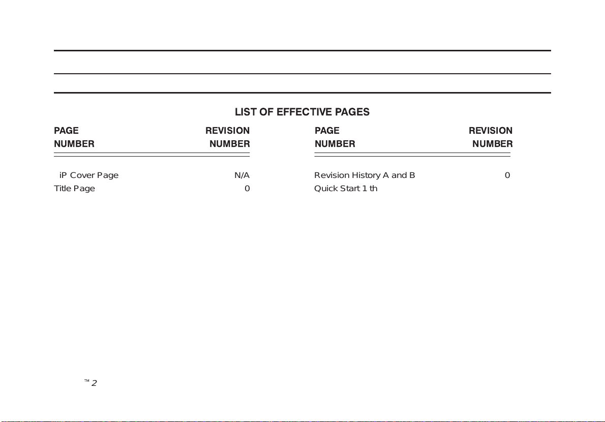
LIST OF EFFECTIVE PAGES
PAGE REVISION PAGE REVISION
NUMBER NUMBER NUMBER NUMBER
TiP Cover Page N/A
Title Page 0
LOGIQt200PRO Series Quick Start
2234974–100 Rev . 0
Revision History A and B 0
Quick Start 1 thru Quick Start 30 0
Revision History A
Page 6
Please verify that you are using the latest revision of this document. Information
pertaining to this document is maintained on GPC (GE Medical Systems Global
Product Configuration). If you need to know the latest revision, contact your
distributor, local GE Sales Representative or in the USA call the GE Ultrasound
Clinical Answer Center at 1-800-682-5327 or 414-524-5698.
Revision History B
LOGIQt200PRO Series Quick Start
2234974–100 Rev . 0
Page 7

Introduction
The Quick Start Guide (TRANSLATED) provides a step-by-step description of the basic features and
operation of the LOGIQt200 PRO Series. It is intended to be used in conjunction with the User Manual in
order to provide the information necessary to operate the system safely .
The Quick Start Guide takes the user from system familiarization through power on, patient data entry , exam
category/preset selection, scan modes/adjustments, basic measurements, report pages, recording images
and power off.
The LOGIQt200 PRO Series manuals are written for users who are familiar with basic ultrasound principals and
techniques. They do not include sonography training or clinical procedures.
Prescription Device (for USA only)
CAUTION: United States law restricts this device to sale or use by or on the order of a physician.
LOGIQt200PRO Series Quick Start
2234974–100 Rev . 0
Quick Start 1
Page 8
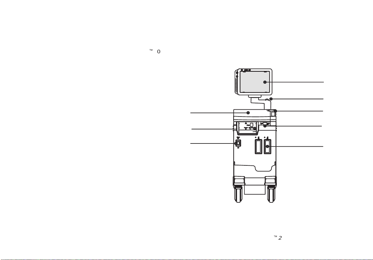
Front View
The following are major features of the LOGIQt200 PRO Series system console. Most features come with the standard
configuration, while other features are options to the standard console.
8. Black & White Monitor
9. Release Button to raise and lower the monitor
10. B/W Video Page Printer (Optional)
11. Power Switch
12. Keyboard
13. Probe Connector
14. Probe Holder
15. MOD Driver (Optional)
5
3
4
1
2
7
8
6
Quick Start 2
LOGIQt200PRO Series Quick Start
2234974–100 Rev . 0
Page 9
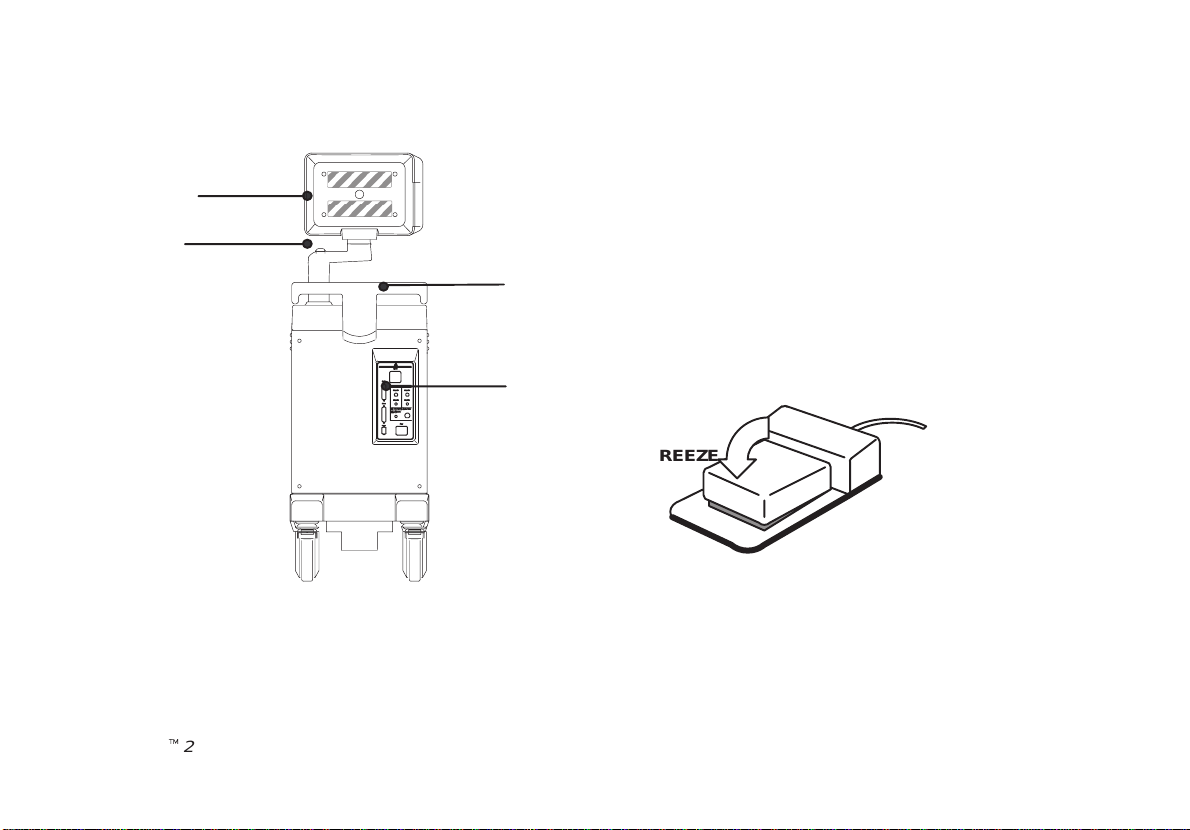
Back View
3
4
1. Rear Handle
2. Peripheral/Accesory Connector Panel
3. Black & White Monitor
4. Release Button to raise and lower the monitor
1
Optional Freeze Foot Switch
2
FREEZE
LOGIQt200PRO Series Quick Start
2234974–100 Rev . 0
Quick Start 3
Page 10
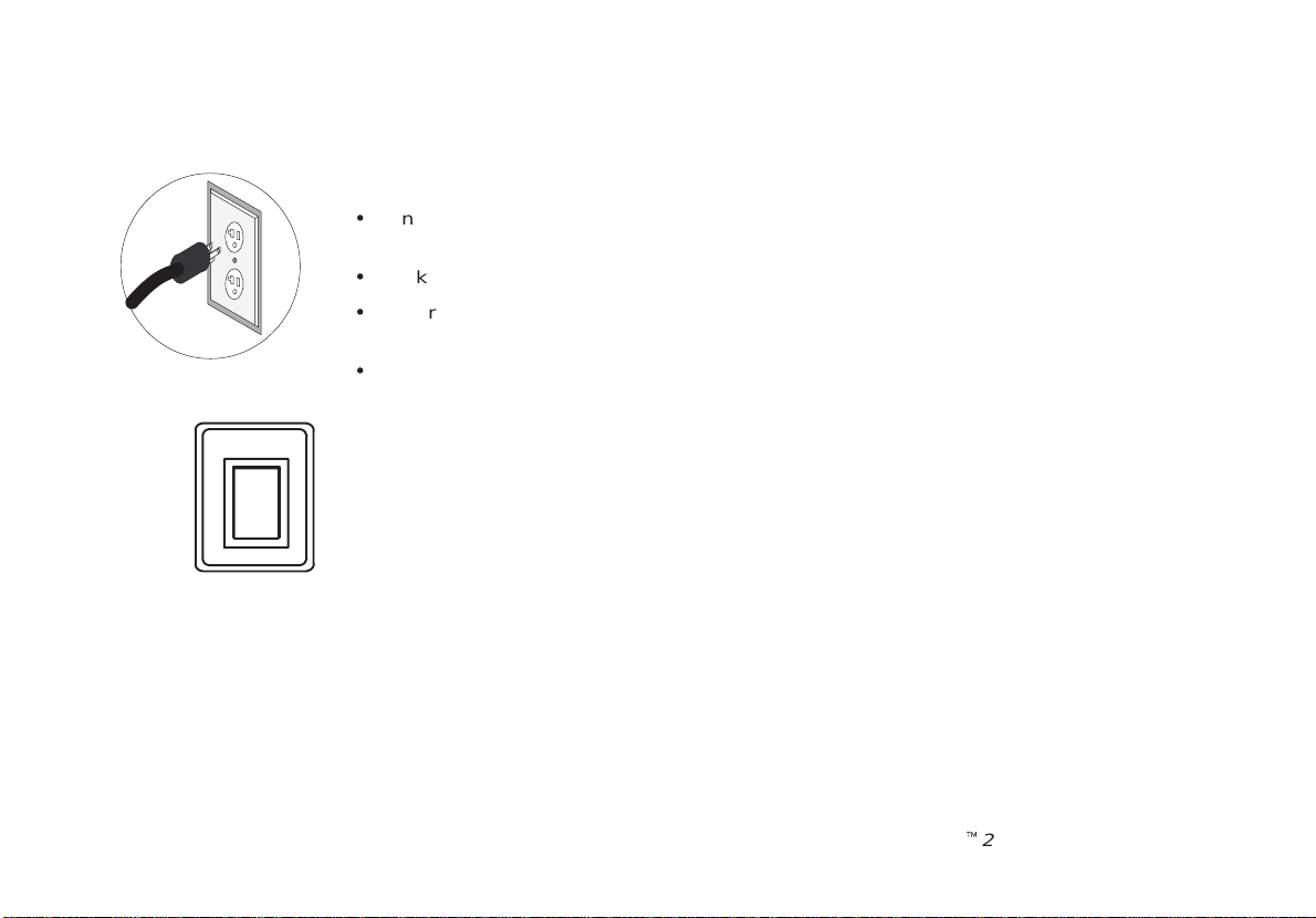
Power On
O
To connect the system to the electrical supply:
S
Ensure that the wall outlet is a minimum 20 amp dedicated circuit for 120 V AC (USA) or 7.5
amp dedicated circuit for 220–240 V AC (Europe).
S
Make sure that the power switch is turned off.
S
Unwrap the power cable. Make sure to allow sufficient slack in the cable so that the plug is
not pulled out of the wall if the system is moved slightly .
S
Push the power plug securely into the wall outlet.
To power on the system press the Power switch, located to the left of the probe connectors, to
the on(I) position.
I
Quick Start 4
LOGIQt200PRO Series Quick Start
2234974–100 Rev . 0
Page 11
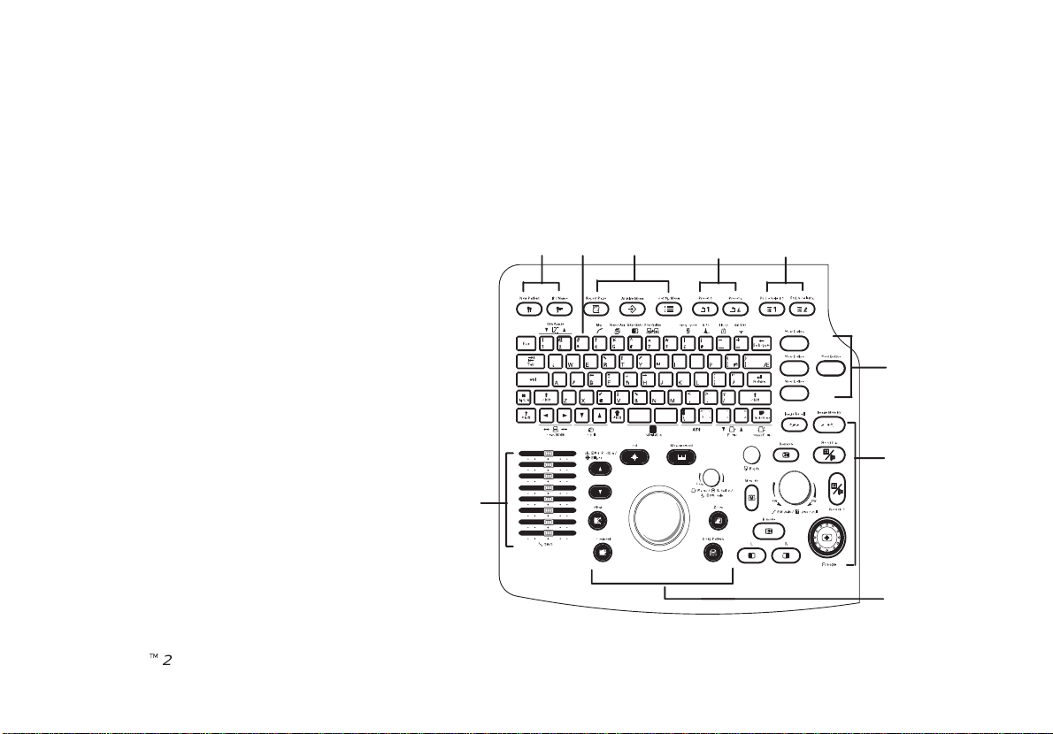
Control Panel Layout
Keyboard
Keyboard controls have been arranged according to
function and usage.This helps minimize operator movement while scanning.
1 : Patient Entry Keys
2 : Alphanumeric Keys
3 : Special Keys
4 : Preset Keys
5 : Probe Select Keys
6 : User Define Keys
7 : Mode, Display/Record Keys
8 : Mesurement/Annotation Keys
9 : TGC Keys
LOGIQt200PRO Series Quick Start
2234974–100 Rev . 0
12
3
4
5
6
7
9
8
Quick Start 5
Page 12

Probe Controls
Probe Select1
A probe is activated by pressing the Probe Select key.
1
Probe Select2
2
Probe Ports
All imaging probes can be plugged into either of the two probe ports.
NOTE: Ensure that the probe port is deactivated before disconnecting the probe.
UNLOCK
LOCK
Quick Start 6
LOGIQt200PRO Series Quick Start
2234974–100 Rev . 0
Page 13

Starting an Exam
Patient Entry Menu
New Patient
Press New Patient key at the beginning of each patient study to reset the system and enter new
patient data. When the New Patient key is pressed, the Patient Entry menu appears.
Use the Trackball to move the highlight cursor to the Exam
Category Selection line. Enter the desired exam number and fill in
the appropriate patient data.
Highlight EXIT and press Return or press New Patient again when
the patient entry menu data has been completed.
The system takes a few seconds to load new exam category
parameters and calibrate the attached transducers before entering
the scan mode.
LOGIQt200PRO Series Quick Start
2234974–100 Rev . 0
EXAM CATEGORY SELECTION : 1
1: RAD/ABDOMEN 2: OBSTETRICS 3: GYNECOLOGY
4: CARDIOLOGY 5: UROLOGY 6: SMALL PARTS
7: USER DEFINE1 8: USER DEFINE2
PT NAME :
PT ID :
NOTE :
Oper ID :
EXAM INFORMATION
AGE: yrs
Ref MD:
COMMENT :
EXIT
[ PATIENT ENTRY MENU ]
Quick Start 7
Page 14

Scan Mode Controls
M Mode
B Mode
Select the desired display mode or combination of display modes (B-Mode or M-Mode).
If the dual display mode (split screen) is desired, the L and R keys activate the Left or Right
displayed image.
R
Scan the desired anatomy . Change modes as desired. Use the mode controls to adjust the image
as necessary.
Quick Start 8
LOGIQt200PRO Series Quick Start
2234974–100 Rev . 0
Page 15

B-Mode Controls
The keyboard controls that effect B-Mode are as follows:
2 3 4 5 6
7
1 8
1. TGC—Controls the gain of the received echoes at a specific depth.
2. Dynamic Range—Controls how echo intensities are converted to
shades of gray scale that can be adjusted.
3. Map—Determines how the echo intensity levels received are
presented as shades of gray .
4. Frame Average—Averages previous frames of image data with the
current frame.
5. Edge Enhance—Brings out subtle tissue differences and boundaries
by enhancing the gray scale differences corresponding to the edges of
structures.
6. Multi Freq—Controls the penetration.
7. Scan Width—Used to widen or narrow the scan width to maximize the
image’s field of view.
8. Scroll—Used to scroll the image presentation up or down in order to
display deeper parts of the body .
LOGIQt200PRO Series Quick Start
2234974–100 Rev . 0
Quick Start 9
Page 16

B-Mode Controls (cont’d)
The keyboard controls that effect B-Mode are as follows:
15 9
10 11 12 13 14
9. Combi Focus—Controls the Focus Combination Value.
10. A TO—Used to optimize the image based upon a specified region of
interest or anatomy within the image.
11. Rotation—Changes the depth at which the selected number of focal
zones are optimized.
12. Reverse—The GE logo at the top of the sector wedge corresponds
to the orientation mark on the probe body . When Reverse is active, the
image flips and the GE logo switches to correspond to the probe mark.
13. Depth—Controls the distance over which the B–Mode images
anatomy.
14. B/M Gain—Controls the amount of echo information displayed in an
image.
15. Biopsy—Enables the electronic biopsy zone(s) available for the
active probe.
Quick Start 10
LOGIQt200PRO Series Quick Start
2234974–100 Rev . 0
Page 17

B-Mode Controls (cont’d)
B-Mode Optimization
Adjustments for... Do the Following... Adjustments for... Do the Following...
Image too grainy
Image too noisy
Cystic Imaging
1. Increase Dynamic Range.
2. Increase Frame Average.
3. Decrease Edge Enhance.
4. Change Map.
1. Decrease B/M GAIN.
2. Decrease Dynamic Range.
3. Increase Frame Average.
4. Increase Edge Enhance.
1. Decrease the B/M GAIN.
2. Decrease Dynamic Range.
3. Use Scan Width to reduce image
width.
4. Change Combi Focus to increase
number of focal zones.
5. Optimize focal zone placement.
Image too soft
Improve Uniformity
Technically Difficult
Patients
1. Decrease Dynamic Range.
2. Increase Edge Enhance.
3. Decrease Frame Average.
4. Change Map.
1. Increase the number of focal zones.
2. Decrease Scan Width.
3. Adjust TGC to compensate for
attenuation.
1. Select the proper probe.
2. Maintain a lower Dynamic Range.
3. Decrease Scan Width for faster
frame rates.
LOGIQt200PRO Series Quick Start
2234974–100 Rev . 0
Quick Start 11
Page 18

M-Mode Controls
Since M-Mode is basically a single B-Mode scan vector displayed over time, basic controls that affect the B-Mode display
also affect the M-Mode display. See
TGC and Depth affect both the M-Mode and B-Mode displays.
If the scan area size is reduced and the position changed, the M-Mode cursor will follow the position change to stay within
the displayed scan area.
The Dual Format keys work the same as in dual B-Mode, but both B-Mode and M-Mode are displayed on the left and right
sides of the screen.
The keyboard controls that effect M-Mode are as follows:
Adjustments for... Do the Following... Adjustments for... Do the Following...
Improve M-Mode
1. Increase/decrease B/M GAIN.
2. Increase Dynamic Range.
Quick Start 9
M-Mode Optimization
for comments on these controls.
Increase Size of Area
of Interest
1. Use M-Mode ZOOM.
Quick Start 12
LOGIQt200PRO Series Quick Start
2234974–100 Rev . 0
Page 19

M-Mode Controls (cont’d)
The keyboard controls that effect B-Mode are as follows:
3
1 2
1. Zoom—Enables zoom function.
2. B/M Gain—Controls the gain of the displayed timeline echoes. To
increase/decrease, turn the control clockwise/ counterclockwise.
3. Sweep Speed—Controls the speed at which the timeline updates
across the speed.
LOGIQt200PRO Series Quick Start
2234974–100 Rev . 0
Quick Start 13
Page 20

Reviewing Cine Images
To display cine images:
Press the Freeze key to stop image acquisition.
When Freeze is activated, rotate the cine Scroll control to display individual image frames which
were stored by the system.
NOTE: Cine frame number is the most current image. The lower the cine frame number, the
older the image. The dynamic range and gain parameters displayed on the screen are valid for
cine frame number zero only .
NOTE: One click of the Cine Scroll knob erases displayed measurements.
B.M.Gain
FWBW
Cine Scroll
Quick Start 14
LOGIQt200PRO Series Quick Start
2234974–100 Rev . 0
Page 21

Image Annotation
Keyboard Annotation
Comment
Pressing the Comment key, assigns the trackball function to controlling the cursor.
The Trackball and Arrow keys on the keyboard are used to move the cursor during the
Comment function. When the blinking cursor is in the desired position, comments may be
typed in. Annotations are entered in the type–over, not insert mode. Be careful not to write
over text when editing.
LOGIQt200PRO Series Quick Start
2234974–100 Rev . 0
Quick Start 15
Page 22

Special Keys–Symbols
Some special annotation symbols can be used by activating the Blue Shift or Green
RT Y
DF GH
CVB
Shift
Shift keys. Green Shift does not function while Blue Shift is active.
Activating Blue Shift will cause the arrow, female and male symbols to be printed on
the screen during the comment function.
Special Keys–Language Symbols
The Green Shift key enables the special symbols shown in green on the keyboard.
Æ
The green symbols shown in the lower right portion of a key will print when the Green
Ç
Shift
Shift is active.
Green symbols for foreign languages can only be used with the proper designated
letters.
The Green symbols shown in the lower right portion of a key print when the Green
Shift is active and that key is pressed.
The Green symbols shown in the upper half of a key will print if the normal shift key
and the appropriate key are pressed while the Green Shift is active.
The Green Shift key acts as a lock function (similar to Caps Lock key). Press again to
exit the Green Shift function.
Quick Start 16
LOGIQt200PRO Series Quick Start
2234974–100 Rev . 0
Page 23

Body Patterns
Body Pattern
Focus Rotation
ECG Gain
Body patterns are a simple graphic of a portion of the anatomy that is frequently scanned.
Press the Body Pattern key to activate Body Patterns.
A body pattern, generally displayed in the lower left corner of the screen, appears.
Cycle through the body patterns by pressing the Body Pattern key
repeatedly .
A Probe Orientation Marker is used to illustrate the probe position.
This marker can be placed with the Trackball and rotated
Probe Orientation
with the Rotation/Focus control. Press Set to complete
the body pattern selection.
Marker
LOGIQt200PRO Series Quick Start
2234974–100 Rev . 0
Quick Start 17
Page 24

Performing Basic Measurements
Basic measurements are displayed on the monitor and not automatically entered into a report page unless a specific
measurement/calculation is selected from the sub–menu. The specific measurement/calculation can be chosen before or
after the basic measurement has been performed.
Scan the desired anatomy and press Freeze.
Press Measurement key. Type of the measurement can be chosen by pressing the
Measurement key.
Measurement
MODE
(After Freeze key is pressed)
Key Pressed
Once Distance
Twice Trace/Circle T ime Interval
Three Times Gray Scale Echo Level Time Slope
Quick Start 18
B M
Ellipse
Tissue Depth
LOGIQt200PRO Series Quick Start
(with B)
Tissue Depth
(Distance)
Depth Difference
2234974–100 Rev . 0
Page 25

Distance (B–Mode) and Tissue Depth (M–Mode)
Perform a distance measurement such as BPD, FL, CRL, LVIDd and LVPWs.
Measurement
Set
Set
LOGIQt200PRO Series Quick Start
2234974–100 Rev . 0
Press Measurement once.
Use the Trackball to move the “” cursor to the measurement start point. Press
Set to fix the measurement start point cursor and to display a second cursor.
Use the Trackball to move the second “” cursor to the measurement end point.
Press Set to complete the measurement and fix the Distance value displayed on
the bottom part of the screen.
Quick Start 19
Page 26

Circumference/Area - Ellipse (B–Mode)
Perform a circumference/area using the ellipse method for calculations such as
AC, HC, LVAMd, LVAd and Volume.
Measurement
Quick Start 20
Set
Ellipse
Set
Press Measurement once.
Use the Trackball to move the “” cursor to either end of the major axis of the
area to measure. Press Set to fix the start point cursor.
Use the Trackball to move the second cursor to the major axis measurement end
point. Press the Ellipse up/down arrow key . An ellipse having an initial circle
shape appears.
Use the Trackball to position the ellipse, as necessary, and to size the measured
axis. Press Set to complete the ellipse measurement and record the
circumference and area.
LOGIQt200PRO Series Quick Start
2234974–100 Rev . 0
Page 27

Circumference/Area - Trace (B–Mode)
Perform a circumference/area using the trace method for calculations such as AC,
HC, L VAMd, LVAd and %stenosis.
Measurement
Measurement
Set
Set
LOGIQt200PRO Series Quick Start
2234974–100 Rev . 0
Press Measurement twice to display a dot “” cursor on the screen. The display
on the bottom of the screen shows the circumference in cm.
Use the Trackball to move the dot “” cursor to the measurement start point.
Press Set to change the dot “” cursor to a “” cursor.
Use the Trackball to trace the measurement area. The circumference displayed
on the bottom of the screen will change with the tracing. Press Set to fix the
Circumference value displayed on the bottom of the screen and calculate the
area.
Quick Start 21
Page 28

Echo Level Measurement
Press Freeze to stop image acquisition.
Measurement Measurement
Quick Start 22
Measurement
Set
Press Measurement three times to enable the echo level function. A box “V”
cursor appears.
Use the Trackball to move the box “V” cursor over the measurement area.
Press Set to fix the Echo value displayed.
LOGIQt200PRO Series Quick Start
2234974–100 Rev . 0
Page 29

Time Interval
Perform a time interval for calculations such as HR, PHT, and ET.
Measurement Measurement
Set
Set
LOGIQt200PRO Series Quick Start
2234974–100 Rev . 0
Press Measurement twice. A “” cursor with a vertical dotted line appears when
the cursor is in the M-Mode portion of the display .
Use the Trackball to move the cursor to the measurement start point. Press Set
to fix the first cursor.
Use the Trackball to move the end cursor to the measurement end point. Press
Set to complete the measurement.
Quick Start 23
Page 30

Slope
Press Freeze to stop image acquisition.
Measurement Measurement Measurement
Set
Set
Quick Start 24
Press Measurement three times. With the cursor in the M-Mode timeline area, a
“” cursor with a vertical dotted line is displayed.
Use the Trackball to position the measurement start point.
Press Set to fix the start point.
Use the Trackball to position the measurement end point.
Press Set to complete the measurement.
LOGIQt200PRO Series Quick Start
2234974–100 Rev . 0
Page 31

Erasing Measurements
Clear
New Patient
B.M.Gain
Pressing Clear or Unfreezing the image erases all measurements and calculations on the
display . Measurements and calculations, however, remain on the report pages.
Pressing New Patient erases all measurements and calculations on the display and clears the
report pages.
Rotating the Cine Scroll control erases measurements.
Adding a new measurement that exceeds the maximum number of allowable measurements
erases the first or oldest measurement.
FWBW
Cine Scroll
LOGIQt200PRO Series Quick Start
2234974–100 Rev . 0
Quick Start 25
Page 32

Report Pages
Report Page
Specific diagnostic exam categories have report pages to summarize measurements and
calculations performed while in that exam category . These categories are Obstetrics,
Urology and Cardiology .
A report page can be displayed by pressing Report Page key.
Hospital Name Oper ID: mm/dd/yy
ID: Patient ID Name: Patient Name AGE:###
LMP(GA):mm/dd/yy G## P## A## E#
Ref MD: NOTE:
POS: PLAC: Page: 1/4
FLUID: PREVIA?: GRADE:
MEASUREMENT CUA GP% CALCULATION
BPD(HADLOCK) Y ###.#mm ##W#D±#D CI (70–86) ###%
HC(HADLOCK) Y ###.#mm ##W#D±#D FL/BPD (71–87) ###%
OFD(HC) ###.#mm ##W#D±#D FL/AC (20–24) ###%
AC(HADLOCK) Y ###.#mm ##W#D±#D FC/HC (??.?–??.?) ###%
TAD(AC) ###.#mm ##W#D±#D HC/AC (???–???) ####
APD(AC) ###.#mm ##W#D±#D
FL(HADLOCK) Y ###.#mm ##W#D±#D EFW(FL,AC,HC,BPD)
CRL(HADLOCK) Y ###.#mm ##W#D±#D ####g±###g ( #lb ##oz )
GS(HELLMAN) Y ###.#mm ##W#D±#D GP>##% (HADLOCK)
AFI(mm) ###
HEART RATE(BPM) ###
BIOPHYS ##/##
GA(OPE) :##W#D EDD(GA) :mm/dd/yy
CUA: :##W#D EDD(CUA):mm/dd/yy
COMMENTS:
EXIT
Quick Start 26
LOGIQt200PRO Series Quick Start
2234974–100 Rev . 0
Page 33

Recording Images
Image Memory
Image Memory
Image Recall
Press Image Memory to temporarily store the maximum of 10 images in system memory .
Pressing Image Memory after the warning deletes the oldest image in system memory and saves
the current displayed image.
Press Image Recall to display the last image stored in system memory.
Use Trackball or Ellipse key to select the desired image to recall.
After recall, comments, measurements and body patterns can be added to the image. The image is
then available for printing and archiving to MOD(option).
Printing
Record2
Use the Record1 or Record2 keys to print the image/report page a B/W Video Page Printer .
Record1
LOGIQt200PRO Series Quick Start
2234974–100 Rev . 0
The function of these keys was established during installation.
Quick Start 27
Page 34

VCR Functions
Ext.Video
The Ext Video key is used to display the External Video on the LOGIQt200 PRO Series
screen.
Probe Cleaning/Disinfection
Probes should be cleaned and disinfected after each use. The Probe Immersion Levels are provided with the probe but
are also pictured in the
Probes
chapter of the User Manual
Quick Start 28
LOGIQt200PRO Series Quick Start
2234974–100 Rev . 0
Page 35

Power Off
To power down the system, press down on the Power switch.
I
O
While the system is running during this power down process, do NOT turn off the
circuit breaker in the back of the machine and do NOT unplug the system from the
wall outlet.x
If the system has not turned off five minutes after pressing the power switch off,
listen for hard drive activity. If there is no hard disk drive activity, the circuit
breaker on the bottom of the power supply can be used to turn off the system. Do
NOT turn off the circuit breaker while the hard disk is working.
LOGIQt200PRO Series Quick Start
2234974–100 Rev . 0
Quick Start 29
Page 36

This page left blank intentionally .
Quick Start 30
LOGIQt200PRO Series Quick Start
2234974–100 Rev . 0
 Loading...