

Page 1

!
"
!
Page 2

2
LOGIQ200 PRO Series Basic Users Manual
2234813–100 Rev 1
Page 3

Regulatory Requirement
This product complies with regulatory requirements of the following European
Directive 93/42/EEC concerning medical devices
This manual is a reference for the LOGIQ200 PRO Series. It applies to all
version of the 3.1X software for the LOGIQ200 PRO Series.
GE Medical Systems
GE Medical Systems: Telex 3797371
P.O. Box 414, Milwaukee, Wisconsin 53201 U.S.A.
(Asia, Pacific, Latin America, North America)
GE Ultrasound Europe: Tel: +49(0)212 2802 0
Kranzbühler GmbH & Co KG
Beethovenstraße 239, Postfach 110560, D–42655
Solingen
GERMANY
Page 4

Page 5

Revision History
%" "#!&
REV DATE REASON FOR CHANGE
0 August 1, 1999 Initial Release
1 January 15, 2000 Software Version 3.02 Release
2 June 15, 2000 Software Version 3.15 Release
3 November 21, 2000 Software Version 3.16 Release
#
%" "#!&
$#!& $!#"
##" #!$
#!$
#!$
#!$
#!$
#!$
#!$
#!$
#!$
#!$
#!$
#!$
#!$
#!$
#!$
#!$
LOGIQ200 PRO Series Basic Users Manual
2234813–100 Rev 1
1
Page 6

Revision History
2
LOGIQ200 PRO Series Basic Users Manual
2234813–100 Rev 1
Page 7

Revision History
Please verify that you are using the latest revision of this document. Information
pertaining to this document is maintained on GPC (GE Medical Systems Global
Product Configuration). If you need to know the latest revision, contact your
distributor, local GE Sales Representative or in the USA call the GE Ultrasound
Clinical Answer Center at 1-800-682–5327 or 414-524-5698.
LOGIQ200 PRO Series Basic Users Manual
2234813–100 Rev 1
3
Page 8

Page 9

Regulatory Requirements
A
Regulatory Requirements
This product complies with the regulatory requirements of the
following:
S Council Directive 93/42/EEC concerning medical devices:
the label affixed to the product testifies compliance
to the Directive.
The location of the CE marking is shown on Safety chapter
of this manual.
European registered place of business:
GE Medical Systems Europe
Quality Assurance Manager
BP 34
F 78533 BUC CEDEX France
Tel: +33 (0)1 30 70 40 40
.
For US
Only
S Medical Device Good Manufacturing Practice Manual
issued by the FDA (Food and Drug Administration,
Department of Health, USA).
S Underwriters’ Laboratories, Inc. (UL), an independent
testing laboratory.
S Canadian Standards Association (CSA).
S International Electrotechnical Commission (IEC),
international standards organizations, when applicable.
Caution: United States law restricts this device to sale or use by
or on the order of a physician.
S
General Electric Medical Systems
EN 46001 certified.
S The original document was written in English.
is ISO 9001 and
LOGIQt200 PRO Series Basic Users Manual
2234813–100 Rev 1
1
Page 10

Regulatory Requirements
NOTE: This equipment generates, uses and can radiate radio frequency energy. The
equipment may cause radio frequency interference to other medical and
non-medical devices and radio communications. To provide reasonable
protection against such interference, this product complies with emissions limits
for a Group 1, Class A Medical Devices Directive as stated in EN 60601–1–2.
However, there is no guarantee that interference will not occur in a particular
installation.
NOTE: If this equipment is found to cause interference (which may be determined by
turning the equipment on and off), the user (or qualified service personnel)
should attempt to correct the problem by one or more of the following
measure(s):
– reorient or relocate the affected device(s)
– increase the separation between the equipment and the affected device
– power the equipment from a source different from that of the affected device
– consult the point of purchase or service representative for further
suggestions
NOTE: The manufacturer is not responsible for any interference caused by using other
than recommended interconnect cables or by unauthorized changes or
modifications to this equipment. Unauthorized changes or modifications could
void the users’ authority to operate the equipment.
NOTE: To comply with the regulations on electromagnetic interference for a Class A
FCC Device, all interconnect cables to peripheral devices must be shielded and
properly grounded. Use of cables not properly shielded and grounded may
result in the equipment causing radio frequency interference in violation of the
FCC regulations.
NOTE: Do not use devices which intentionally transmit RF Signals (cellular phones,
transceivers, or radio controlled products) in the vicinity of the equipment as it
may cause performance outside the published specifications. Keep the power
to these type devices turned off when near this equipment.
The medical staff in charge of this equipment is required to instruct technicians,
patients, and other people who may be around this equipment to fully comply
with the above requirement.
2
LOGIQ200 PRO Series Basic Users Manual
2234813–100 Rev 1
Page 11

Table of Contents
Front Matter
Title Page
Revision History A. . . . . . . . . . . . . . . . . . . . . . . . . . . . . . .
Regulatory Requirements
Table of Contents Table of Contents 1. . . . . . . . . . . . . . . . . . . . . . . . . . . . . .
Chapter 1 – Introduction
System Overview 1–2. . . . . . . . . . . . . . . . . . . . . . . . . . . .
Attention 1–2. . . . . . . . . . . . . . . . . . . . . . . . . . . . . . . . . . . . . . . . .
Prescription Device 1–2. . . . . . . . . . . . . . . . . . . . . . . . . . . . . . . .
System Components 1–2. . . . . . . . . . . . . . . . . . . . . . . . . . . . . .
Documentation 1–3. . . . . . . . . . . . . . . . . . . . . . . . . . . . . . . . . . .
Introduction 1–4. . . . . . . . . . . . . . . . . . . . . . . . . . . . . . . . . . . . . .
General Indications for Use 1–5. . . . . . . . . . . . . . . . . . . . . . . . .
Contraindications 1–5. . . . . . . . . . . . . . . . . . . . . . . . . . . . . . . . .
Table of Contents
Regulatory Req 1. . . . . . . . . . . . . . . . . . . . . .
Who to Contact 1–6. . . . . . . . . . . . . . . . . . . . . . . . . . . . . .
Who To Contact 1–6. . . . . . . . . . . . . . . . . . . . . . . . . . . . . . . . . . .
How This Book is Organized 1–9. . . . . . . . . . . . . . . . . .
Manual Content 1–9. . . . . . . . . . . . . . . . . . . . . . . . . . . . . . . . . . .
Manual Format 1–11. . . . . . . . . . . . . . . . . . . . . . . . . . . . . . . . . . .
Chapter 2 – Safety
Safety Precautions 2–2. . . . . . . . . . . . . . . . . . . . . . . . . . .
Icon Description 2–2. . . . . . . . . . . . . . . . . . . . . . . . . . . . . . . . . .
Hazard Symbols 2–3. . . . . . . . . . . . . . . . . . . . . . . . . . . . . . . . . .
Patient Safety 2–4. . . . . . . . . . . . . . . . . . . . . . . . . . . . . . . . . . . .
Equipment and Personnel Safety 2–6. . . . . . . . . . . . . . . . . . . .
Related Hazards 2–6. . . . . . . . . . . . . . . . . . . . . . . . . . . . . . . . . .
Device Labels 2–8. . . . . . . . . . . . . . . . . . . . . . . . . . . . . . . . . . . .
Acoustic Output 2–16. . . . . . . . . . . . . . . . . . . . . . . . . . . . . . . . . . .
Controls Affecting Output 2–16. . . . . . . . . . . . . . . . . . . . . . . . . .
Warning Label Locations 2–18. . . . . . . . . . . . . . . . . . . . . . . . . . .
LOGIQ200 PRO Series Basic Users Manual
2234813–100 Rev 1
1
Page 12

Table of Contents
Chapter 3 – Preparing the System for Use
Site Requirements 3–2. . . . . . . . . . . . . . . . . . . . . . . . . . .
Introduction 3–2. . . . . . . . . . . . . . . . . . . . . . . . . . . . . . . . . . . . . .
Before the system arrives 3–3. . . . . . . . . . . . . . . . . . . . . . . . . .
Environmental Requirements 3–4. . . . . . . . . . . . . . . . . . . . . . .
Console Overview 3–5. . . . . . . . . . . . . . . . . . . . . . . . . . .
Console graphics 3–5. . . . . . . . . . . . . . . . . . . . . . . . . . . . . . . . .
Storage areas 3–7. . . . . . . . . . . . . . . . . . . . . . . . . . . . . . . . . . . .
Peripheral/Accessory Connector Panel 3–8. . . . . . . . . . . . . .
Foot Switch (option) 3–10. . . . . . . . . . . . . . . . . . . . . . . . . . . . . . .
System Positioning/Transporting 3–11. . . . . . . . . . . . .
Moving the System 3–11. . . . . . . . . . . . . . . . . . . . . . . . . . . . . . . .
Transporting the System 3–13. . . . . . . . . . . . . . . . . . . . . . . . . . .
Wheels 3–14. . . . . . . . . . . . . . . . . . . . . . . . . . . . . . . . . . . . . . . . . .
Powering On the System 3–15. . . . . . . . . . . . . . . . . . . . .
Connecting and Using the System 3–15. . . . . . . . . . . . . . . . . . .
Power Up Sequence 3–17. . . . . . . . . . . . . . . . . . . . . . . . . . . . . .
Adjusting the Display Monitor 3–18. . . . . . . . . . . . . . . .
Rotate, tilt, raise and lower the monitor 3–18. . . . . . . . . . . . . .
Brightness and Contrast 3–19. . . . . . . . . . . . . . . . . . . . . . . . . . .
Probes 3–21. . . . . . . . . . . . . . . . . . . . . . . . . . . . . . . . . . . . . .
Introduction 3–21. . . . . . . . . . . . . . . . . . . . . . . . . . . . . . . . . . . . . .
Connecting the Probe 3–21. . . . . . . . . . . . . . . . . . . . . . . . . . . . .
Activating the Probe 3–23. . . . . . . . . . . . . . . . . . . . . . . . . . . . . . .
Storing the Probe 3–23. . . . . . . . . . . . . . . . . . . . . . . . . . . . . . . . .
Deactivating the Probe 3–24. . . . . . . . . . . . . . . . . . . . . . . . . . . . .
Operator Controls 3–25. . . . . . . . . . . . . . . . . . . . . . . . . . .
Control Panel Map 3–25. . . . . . . . . . . . . . . . . . . . . . . . . . . . . . . .
Preset Keys 3–26. . . . . . . . . . . . . . . . . . . . . . . . . . . . . . . . . . . . . .
Measurement and Annotation 3–27. . . . . . . . . . . . . . . . . . . . . .
Mode, Display and Record 3–29. . . . . . . . . . . . . . . . . . . . . . . . .
Keyboard 3–31. . . . . . . . . . . . . . . . . . . . . . . . . . . . . . . . . . . . . . . .
Special Key Function 3–32. . . . . . . . . . . . . . . . . . . . . . . . . . . . . .
2
LOGIQ200 PRO Series Basic Users Manual
2234813–100 Rev 1
Page 13

Chapter 4 – Preparing for an Exam
Beginning an Exam 4–2. . . . . . . . . . . . . . . . . . . . . . . . . .
Introduction 4–2. . . . . . . . . . . . . . . . . . . . . . . . . . . . . . . . . . . . . .
Beginning a New Patient 4–2. . . . . . . . . . . . . . . . . . . . . . . . . . .
OB/GYN Exam Category 4–6. . . . . . . . . . . . . . . . . . . . . . . . . . .
ID/Name 4–6. . . . . . . . . . . . . . . . . . . . . . . . . . . . . . . . . . . . . . . . .
Chapter 5 – Modes
B–Mode 5–2. . . . . . . . . . . . . . . . . . . . . . . . . . . . . . . . . . . . .
Introduction 5–2. . . . . . . . . . . . . . . . . . . . . . . . . . . . . . . . . . . . . .
Optimizing the Image 5–6. . . . . . . . . . . . . . . . . . . . . . . . . . . . . .
M-Mode 5–17. . . . . . . . . . . . . . . . . . . . . . . . . . . . . . . . . . . . .
Introduction 5–17. . . . . . . . . . . . . . . . . . . . . . . . . . . . . . . . . . . . . .
M-Mode Display 5–17. . . . . . . . . . . . . . . . . . . . . . . . . . . . . . . . . .
Optimizing the Timeline 5–18. . . . . . . . . . . . . . . . . . . . . . . . . . . .
Mixed Mode Display Formats 5–23. . . . . . . . . . . . . . . . .
Chapter 6 – Scanning/Display Functions
Zooming an Image 6–2. . . . . . . . . . . . . . . . . . . . . . . . . . .
Introduction 6–2. . . . . . . . . . . . . . . . . . . . . . . . . . . . . . . . . . . . . .
Zooming an Image 6–2. . . . . . . . . . . . . . . . . . . . . . . . . . . . . . . .
Table of Contents
Freezing an Image 6–6. . . . . . . . . . . . . . . . . . . . . . . . . . .
Introduction 6–6. . . . . . . . . . . . . . . . . . . . . . . . . . . . . . . . . . . . . .
Foot Switch option 6–6. . . . . . . . . . . . . . . . . . . . . . . . . . . . . . . .
Using Cine 6–7. . . . . . . . . . . . . . . . . . . . . . . . . . . . . . . . . .
Introduction 6–7. . . . . . . . . . . . . . . . . . . . . . . . . . . . . . . . . . . . . .
Accessing Cine 6–8. . . . . . . . . . . . . . . . . . . . . . . . . . . . . . . . . . .
Cine Gauge 6–8. . . . . . . . . . . . . . . . . . . . . . . . . . . . . . . . . . . . . .
Exiting Cine 6–8. . . . . . . . . . . . . . . . . . . . . . . . . . . . . . . . . . . . . .
Annotating an Image 6–9. . . . . . . . . . . . . . . . . . . . . . . . .
Introduction 6–9. . . . . . . . . . . . . . . . . . . . . . . . . . . . . . . . . . . . . .
Annotation Library 6–11. . . . . . . . . . . . . . . . . . . . . . . . . . . . . . . . .
Adding Comments to an Image 6–12. . . . . . . . . . . . . . . . . . . . .
Special Annotation Keys 6–13. . . . . . . . . . . . . . . . . . . . . . . . . . .
Editing Annotations 6–14. . . . . . . . . . . . . . . . . . . . . . . . . . . . . . . .
Body Patterns 6–15. . . . . . . . . . . . . . . . . . . . . . . . . . . . . . . . . . . .
LOGIQ200 PRO Series Basic Users Manual
2234813–100 Rev 1
3
Page 14

Table of Contents
Chapter 7 – General Measurements and Calculations
Introduction 7–2. . . . . . . . . . . . . . . . . . . . . . . . . . . . . . . . .
Overview 7–2. . . . . . . . . . . . . . . . . . . . . . . . . . . . . . . . . . . . . . . .
General Instructions 7–2. . . . . . . . . . . . . . . . . . . . . . . . . . . . . . .
Erasing Measurements 7–3. . . . . . . . . . . . . . . . . . . . . . . . . . . .
Locating measurement controls 7–4. . . . . . . . . . . . . . . . . . . . .
Measurement Key 7–5. . . . . . . . . . . . . . . . . . . . . . . . . . . . . . . . .
Cursors 7–5. . . . . . . . . . . . . . . . . . . . . . . . . . . . . . . . . . . . . . . . . .
B-Mode Measurements 7–6. . . . . . . . . . . . . . . . . . . . . . .
Distance Measurement 7–6. . . . . . . . . . . . . . . . . . . . . . . . . . . .
Circumference/Area (Ellipse) Measurement 7–8. . . . . . . . . .
Circumference/Area (Trace) Measurement 7–10. . . . . . . . . . .
Echo Level Measurement 7–12. . . . . . . . . . . . . . . . . . . . . . . . . .
M-Mode Measurements 7–13. . . . . . . . . . . . . . . . . . . . . . .
Overview 7–13. . . . . . . . . . . . . . . . . . . . . . . . . . . . . . . . . . . . . . . .
Tissue depth 7–14. . . . . . . . . . . . . . . . . . . . . . . . . . . . . . . . . . . . .
Time 7–15. . . . . . . . . . . . . . . . . . . . . . . . . . . . . . . . . . . . . . . . . . . .
Slope 7–16. . . . . . . . . . . . . . . . . . . . . . . . . . . . . . . . . . . . . . . . . . . .
Chapter 8 – Abdomen and Small Parts
General Calculations 8–2. . . . . . . . . . . . . . . . . . . . . . . . .
Overview 8–2. . . . . . . . . . . . . . . . . . . . . . . . . . . . . . . . . . . . . . . .
Measuring Volume 8–5. . . . . . . . . . . . . . . . . . . . . . . . . . . . . . . .
Measuring Angle 8–8. . . . . . . . . . . . . . . . . . . . . . . . . . . . . . . . . .
Measuring Stenosis Area Ratio (% stenosis) 8–9. . . . . . . . . .
Echo Level Histogram 8–15. . . . . . . . . . . . . . . . . . . . . . . . . . . . .
Measuring heart rate (HR) 8–17. . . . . . . . . . . . . . . . . . . . . . . . .
Helpful hints 8–19. . . . . . . . . . . . . . . . . . . . . . . . . . . . . . . . . . . . . .
General Calculation Formulas 8–19. . . . . . . . . . . . . . . . . . . . . .
4
LOGIQ200 PRO Series Basic Users Manual
2234813–100 Rev 1
Page 15

Chapter 9 – OB/GYN
Exam Preparation 9–3. . . . . . . . . . . . . . . . . . . . . . . . . . . .
Overview 9–3. . . . . . . . . . . . . . . . . . . . . . . . . . . . . . . . . . . . . . . .
OB Measurements and Formulas 9–4. . . . . . . . . . . . .
Introduction 9–4. . . . . . . . . . . . . . . . . . . . . . . . . . . . . . . . . . . . . .
OB Format Selection 9–4. . . . . . . . . . . . . . . . . . . . . . . . . . . . . .
OB Measurement Menus and Formulas 9–4. . . . . . . . . . . . . .
OB Summary Reports 9–17. . . . . . . . . . . . . . . . . . . . . . . .
Overview 9–17. . . . . . . . . . . . . . . . . . . . . . . . . . . . . . . . . . . . . . . .
Starting an Exam 9–19. . . . . . . . . . . . . . . . . . . . . . . . . . . . . . . . .
Formulas 9–20. . . . . . . . . . . . . . . . . . . . . . . . . . . . . . . . . . . . . . . .
Editing the OB Summary Report 9–21. . . . . . . . . . . . . . . . . . . .
Gestational Age Error Markers 9–22. . . . . . . . . . . . . . . . . . . . . .
OB Report Layout 9–23. . . . . . . . . . . . . . . . . . . . . . . . . . . . . . . . .
Measurement Averaging Page Layout 9–27. . . . . . . . . . . . . . .
OB Anatomical Survey Page Layout 9–29. . . . . . . . . . . . . . . . .
OB Trend Graph Page Layout 9–30. . . . . . . . . . . . . . . . . . . . . .
OB Trend Graph Labeling 9–31. . . . . . . . . . . . . . . . . . . . . . . . . .
Changing OB Trend Graph Selection 9–33. . . . . . . . . . . . . . . .
Input Previous Data Page Layout 9–34. . . . . . . . . . . . . . . . . . .
Table of Contents
Fetal Trend Management 9–36. . . . . . . . . . . . . . . . . . . . .
Overview 9–36. . . . . . . . . . . . . . . . . . . . . . . . . . . . . . . . . . . . . . . .
Storing Patient Information 9–36. . . . . . . . . . . . . . . . . . . . . . . . .
Growth Trending 9–41. . . . . . . . . . . . . . . . . . . . . . . . . . . . . . . . . .
Patient List Management 9–42. . . . . . . . . . . . . . . . . . . . . . . . . . .
MGOB–Multigestational 9–47. . . . . . . . . . . . . . . . . . . . . .
Overview 9–47. . . . . . . . . . . . . . . . . . . . . . . . . . . . . . . . . . . . . . . .
Patient Entry Menu 9–47. . . . . . . . . . . . . . . . . . . . . . . . . . . . . . . .
Distinguishing Each Fetus 9–48. . . . . . . . . . . . . . . . . . . . . . . . . .
Measurements/Calculations 9–48. . . . . . . . . . . . . . . . . . . . . . . .
Change the Number of Fetuses 9–49. . . . . . . . . . . . . . . . . . . . .
Report Page Layout 9–50. . . . . . . . . . . . . . . . . . . . . . . . . . . . . . .
OB Graph 9–52. . . . . . . . . . . . . . . . . . . . . . . . . . . . . . . . . . . . . . . .
GYN Measurements 9–54. . . . . . . . . . . . . . . . . . . . . . . . . .
B-Mode 9–54. . . . . . . . . . . . . . . . . . . . . . . . . . . . . . . . . . . . . . . . . .
GYN Summary Report 9–60. . . . . . . . . . . . . . . . . . . . . . . .
Overview 9–60. . . . . . . . . . . . . . . . . . . . . . . . . . . . . . . . . . . . . . . .
GYN Report Layout 9–62. . . . . . . . . . . . . . . . . . . . . . . . . . . . . . .
GYN Calculation Formulas 9–63. . . . . . . . . . . . . . . . . . . . . . . . .
Measurement Averaging Page Layout 9–64. . . . . . . . . . . . . . .
IVF Report Page Layout 9–65. . . . . . . . . . . . . . . . . . . . . . . . . . .
LOGIQ200 PRO Series Basic Users Manual
2234813–100 Rev 1
5
Page 16

Table of Contents
Chapter 10 – Cardiology
Introduction 10–2. . . . . . . . . . . . . . . . . . . . . . . . . . . . . . . . .
Overview 10–2. . . . . . . . . . . . . . . . . . . . . . . . . . . . . . . . . . . . . . . .
Cardiology Calculations Measurement Menus 10–5. . . . . . . .
General Guidelines 10–6. . . . . . . . . . . . . . . . . . . . . . . . . . . . . . . .
Auto Sequence Measurement 10–6. . . . . . . . . . . . . . . . . . . . . .
BSA Calculation Methods 10–7. . . . . . . . . . . . . . . . . . . . . . . . . .
LV Analysis Measurements 10–8. . . . . . . . . . . . . . . . . . .
Cubed, Teichholz, Gibson Methods 10–8. . . . . . . . . . . . . . . . . .
Cubed Method Formulas 10–9. . . . . . . . . . . . . . . . . . . . . . . . . . .
Teichholz Method Formulas 10–10. . . . . . . . . . . . . . . . . . . . . . . .
Gibson Method Formulas 10–11. . . . . . . . . . . . . . . . . . . . . . . . . .
Bullet and Modified Simpson’s Rule Methods 10–12. . . . . . . . .
Bullet Method Formulas 10–13. . . . . . . . . . . . . . . . . . . . . . . . . . . .
Modified Simpson’s Rule Method Formulas 10–14. . . . . . . . . . .
Single Plane Ellipsoid Methods 10–15. . . . . . . . . . . . . . . . . . . . .
Bi Plane Ellipsoid Methods 10–15. . . . . . . . . . . . . . . . . . . . . . . . .
Single Plane Ellipsoid Method Formulas 10–16. . . . . . . . . . . . .
Bi Plane Ellipsoid Method Formulas 10–17. . . . . . . . . . . . . . . . .
M–Mode Analysis Measurement 10–18. . . . . . . . . . . . . .
Overview 10–18. . . . . . . . . . . . . . . . . . . . . . . . . . . . . . . . . . . . . . . .
M-Mode Analysis – Left/Right Ventricle (M-LV/RV) 10–19. . . . .
M-Mode Analysis – Left/Right Ventricle (M-LV/RV) Formulas 10–20. . . . . . . . . . .
M-Mode Analysis – Mitral Valve (M-MV) 10–22. . . . . . . . . . . . . .
M-Mode Analysis – Mitral Valve (M-MV) Formulas 10–23. . . . .
M-Mode Analysis – Aortic Valve (M-AV) 10–24. . . . . . . . . . . . . .
M-Mode Analysis – Aortic Valve (M-AV) Formulas 10–25. . . . .
M-Mode Analysis – Pulmonic Valve (M-PV) 10–26. . . . . . . . . . .
M-Mode Analysis – Pulmonic Valve (M-PV) Formulas 10–27. .
M-Mode Analysis – Tricuspid Valve (M-TV) 10–28. . . . . . . . . . .
M-Mode Analysis – Tricuspid Valve (M-TV) Formulas 10–29. .
Additional Cardiology Calculations 10–30. . . . . . . . . . .
ECG Option 10–31. . . . . . . . . . . . . . . . . . . . . . . . . . . . . . . . .
Overview 10–31. . . . . . . . . . . . . . . . . . . . . . . . . . . . . . . . . . . . . . . .
ECG Lead Placement 10–32. . . . . . . . . . . . . . . . . . . . . . . . . . . . .
ECG Default Preset 10–33. . . . . . . . . . . . . . . . . . . . . . . . . . . . . . .
ECG Controls 10–33. . . . . . . . . . . . . . . . . . . . . . . . . . . . . . . . . . . .
6
LOGIQ200 PRO Series Basic Users Manual
2234813–100 Rev 1
Page 17

Chapter 11 – Urology
Urology Calculations 11–2. . . . . . . . . . . . . . . . . . . . . . . . .
Overview 1 1–2. . . . . . . . . . . . . . . . . . . . . . . . . . . . . . . . . . . . . . . .
Urology Summary Report Page 11–2. . . . . . . . . . . . . . . . . . . . .
Using the Transaxial Probe 11–8. . . . . . . . . . . . . . . . . . .
Transaxial Probe Preparation 11–8. . . . . . . . . . . . . . . . . . . . . . .
Use of Transaxial Probe with Volume Stepper Device 11–9. .
Stepper Volume Calculation 11–13. . . . . . . . . . . . . . . . . .
Stepper Volume Formula 11–13. . . . . . . . . . . . . . . . . . . . . . . . . . .
Description 11–14. . . . . . . . . . . . . . . . . . . . . . . . . . . . . . . . . . . . . . .
Prerequisite 1 1–14. . . . . . . . . . . . . . . . . . . . . . . . . . . . . . . . . . . . . .
Area Measurement for Each Slice (Step Increment) 11–16. . .
Chapter 12 – Recording Images
Archiving Images 12–2. . . . . . . . . . . . . . . . . . . . . . . . . . . .
Image Memory 12–2. . . . . . . . . . . . . . . . . . . . . . . . . . . . . . . . . . .
Recall 12–4. . . . . . . . . . . . . . . . . . . . . . . . . . . . . . . . . . . . . . . . . . .
Helpful hints 12–4. . . . . . . . . . . . . . . . . . . . . . . . . . . . . . . . . . . . . .
Peripheral Devices 12–5. . . . . . . . . . . . . . . . . . . . . . . . . . . . . . . .
Black /White Video Page Printer Operations 12–6. . . . . . . . . .
Multi-Image Camera (MIC) (IIE Model 460) 12–8. . . . . . . . . . .
Video cassette recorder (VCR) 12–9. . . . . . . . . . . . . . . . . . . . . .
MOD Image Archive (option) 12–10. . . . . . . . . . . . . . . . . . . . . . .
Table of Contents
Chapter 13 – Customizing Your System
Introduction 13–2. . . . . . . . . . . . . . . . . . . . . . . . . . . . . . . . .
Overview 13–2. . . . . . . . . . . . . . . . . . . . . . . . . . . . . . . . . . . . . . . .
Setup Menu Command Lines 13–3. . . . . . . . . . . . . . . . . . . . . . .
Basic Operation 13–5. . . . . . . . . . . . . . . . . . . . . . . . . . . . . . . . . . .
Menu Structure 13–8. . . . . . . . . . . . . . . . . . . . . . . . . . . . . .
General System 1 Setup (page 1 of 11) 13–8. . . . . . . . . . . . . .
General System 2 Setup (page 2 of 11) 13–12. . . . . . . . . . . . . .
Probe Parameter 1 Setup (page 3 of 11) 13–19. . . . . . . . . . . . .
Probe Parameter 2 Setup (page 4 of 11) 13–22. . . . . . . . . . . . .
Image Display & Application Setup (page 5 of 11) 13–24. . . . .
Body Pattern Setup (page 6 of 11) 13–28. . . . . . . . . . . . . . . . . . .
Comment Setup (page 7 of 11) 13–31. . . . . . . . . . . . . . . . . . . . .
Measurement Setup (page 8 of 11) 13–32. . . . . . . . . . . . . . . . . .
Patient Entry Setup (page 9 of 11) 13–45. . . . . . . . . . . . . . . . . . .
User Define Category and Key Setup (page 10 of 11) 13–47. .
User Utility (page 11 of 11) 13–48. . . . . . . . . . . . . . . . . . . . . . . . .
LOGIQ200 PRO Series Basic Users Manual
2234813–100 Rev 1
7
Page 18

Table of Contents
Chapter 14 – Probes and Biopsy
Probe Overview 14–2. . . . . . . . . . . . . . . . . . . . . . . . . . . . . .
Ergonomics 14–2. . . . . . . . . . . . . . . . . . . . . . . . . . . . . . . . . . . . . .
Applications 14–5. . . . . . . . . . . . . . . . . . . . . . . . . . . . . . . . . . . . . .
Specifications 14–6. . . . . . . . . . . . . . . . . . . . . . . . . . . . . . . . . . . .
Connecting and Disconnecting a Probe 14–7. . . . . . . . . . . . . .
Care and Maintenance 14–8. . . . . . . . . . . . . . . . . . . . . . . . . . . . .
Probe Safety 14–9. . . . . . . . . . . . . . . . . . . . . . . . . . . . . . . . . . . . .
Probe handling and infection control 14–11. . . . . . . . . . . . . . . . .
Coupling gels 14–17. . . . . . . . . . . . . . . . . . . . . . . . . . . . . . . . . . . . .
Planned Maintenance 14–17. . . . . . . . . . . . . . . . . . . . . . . . . . . . .
Probe Discussion 14–18. . . . . . . . . . . . . . . . . . . . . . . . . . . .
Introduction 14–18. . . . . . . . . . . . . . . . . . . . . . . . . . . . . . . . . . . . . .
Curved Array (Convex) Probes 14–19. . . . . . . . . . . . . . . . . . . . .
Linear Array Probes 14–22. . . . . . . . . . . . . . . . . . . . . . . . . . . . . . .
Sector Array Probes 14–24. . . . . . . . . . . . . . . . . . . . . . . . . . . . . . .
Biopsy Special Concerns 14–25. . . . . . . . . . . . . . . . . . . . .
Precautions Concerning the Use of Biopsy Procedures 14–25
Guidezones 14–27. . . . . . . . . . . . . . . . . . . . . . . . . . . . . . . . .
Biopsy Procedure 14–27. . . . . . . . . . . . . . . . . . . . . . . . . . . . . . . . .
Needle Guide Type Selection 14–28. . . . . . . . . . . . . . . . . . . . . . .
Biopsy Guide Attachment 14–30. . . . . . . . . . . . . . . . . . . . . . . . . .
MTZ Probe Biopsy Guide 14–33. . . . . . . . . . . . . . . . . . . . . . . . . .
Biopsy Probes 14–36. . . . . . . . . . . . . . . . . . . . . . . . . . . . . . . . . . . .
8
LOGIQ200 PRO Series Basic Users Manual
2234813–100 Rev 1
Page 19

Chapter 15 – User Maintenance
System Data 15–2. . . . . . . . . . . . . . . . . . . . . . . . . . . . . . . . .
Specifications 15–2. . . . . . . . . . . . . . . . . . . . . . . . . . . . . . . . . . . .
LOGIQ 200 PRO Series Clinical Measurement Accuracy 15–4
LOGIQ 200 PRO Series Clinical Calculation Accuracy 15–6.
Warranties 15–7. . . . . . . . . . . . . . . . . . . . . . . . . . . . . . . . . .
Scope and Duration of Warranties 15–7. . . . . . . . . . . . . . . . . . .
Warranty Exclusions 15–9. . . . . . . . . . . . . . . . . . . . . . . . . . . . . . .
Exclusive Warranty Remedies 15–10. . . . . . . . . . . . . . . . . . . . . .
System Care and Maintenance 15–11. . . . . . . . . . . . . . . .
Overview 15–11. . . . . . . . . . . . . . . . . . . . . . . . . . . . . . . . . . . . . . . .
Inspecting the System 15–11. . . . . . . . . . . . . . . . . . . . . . . . . . . . .
Weekly Maintenance 15–12. . . . . . . . . . . . . . . . . . . . . . . . . . . . . .
Planned Maintenance 15–16. . . . . . . . . . . . . . . . . . . . . . . . . . . . .
Troubleshooting 15–17. . . . . . . . . . . . . . . . . . . . . . . . . . . . .
Introduction 15–17. . . . . . . . . . . . . . . . . . . . . . . . . . . . . . . . . . . . . .
Loose cables 15–17. . . . . . . . . . . . . . . . . . . . . . . . . . . . . . . . . . . . .
Display Messages 15–18. . . . . . . . . . . . . . . . . . . . . . . . . . . . . . . . .
System Error Message Description 15–19. . . . . . . . . . . . . . . . . .
Operation Error Message Description 15–20. . . . . . . . . . . . . . . .
Operation Guide Message Description 15–21. . . . . . . . . . . . . . .
Table of Contents
Assistance 15–22. . . . . . . . . . . . . . . . . . . . . . . . . . . . . . . . . .
Clinical Questions 15–22. . . . . . . . . . . . . . . . . . . . . . . . . . . . . . . . .
Service Questions 15–22. . . . . . . . . . . . . . . . . . . . . . . . . . . . . . . . .
Literature 15–22. . . . . . . . . . . . . . . . . . . . . . . . . . . . . . . . . . . . . . . .
Accessories 15–22. . . . . . . . . . . . . . . . . . . . . . . . . . . . . . . . . . . . . .
Supplies/Accessories 15–23. . . . . . . . . . . . . . . . . . . . . . . . . . . . . .
LOGIQ200 PRO Series Basic Users Manual
2234813–100 Rev 1
9
Page 20

Table of Contents
Chapter 16 – Acoustic Output
Bioeffects 16–2. . . . . . . . . . . . . . . . . . . . . . . . . . . . . . . . . . .
Concerns Surrounding the Use of Diagnostic Ultrasound 16–2
Operator Awareness and Actions to Minimize Bioeffect 16–5
Implementing ALARA Methods 16–8. . . . . . . . . . . . . . . . . . . . .
Training and User Assistance 16–9. . . . . . . . . . . . . . . . . . . . . . .
IEC Acoustic Output Tables 16–10. . . . . . . . . . . . . . . . . .
IEC Acoustic Output Tables 16–10. . . . . . . . . . . . . . . . . . . . . . . .
Index
10
LOGIQ200 PRO Series Basic Users Manual
2234813–100 Rev 1
Page 21

System Overview
A
Attention
Prescription Device
System Overview
This manual contains enough information to operate the system
safely. Advanced equipment training will be provided by a
factory trained Applications Specialist for the agreed upon time
period.
Read and understand all instructions in this manual before
attempting to use the LOGIQt200 PRO Series system.
Keep this User’s Manual with the equipment at all times.
Periodically review the procedures for operation and safety
precautions.
.
System Components
For US
Only
.
Caution: United States law restricts this device to sale or use by
or on the order of a physician.
Refer to the Service Manual (2235374) for the LOGIQt200 PRO
Series sys te m c o m ponents.
2
LOGIQt200 PRO Series Basic Users Manual
2234813–100 Rev 1
Page 22
Documentation
System Overview
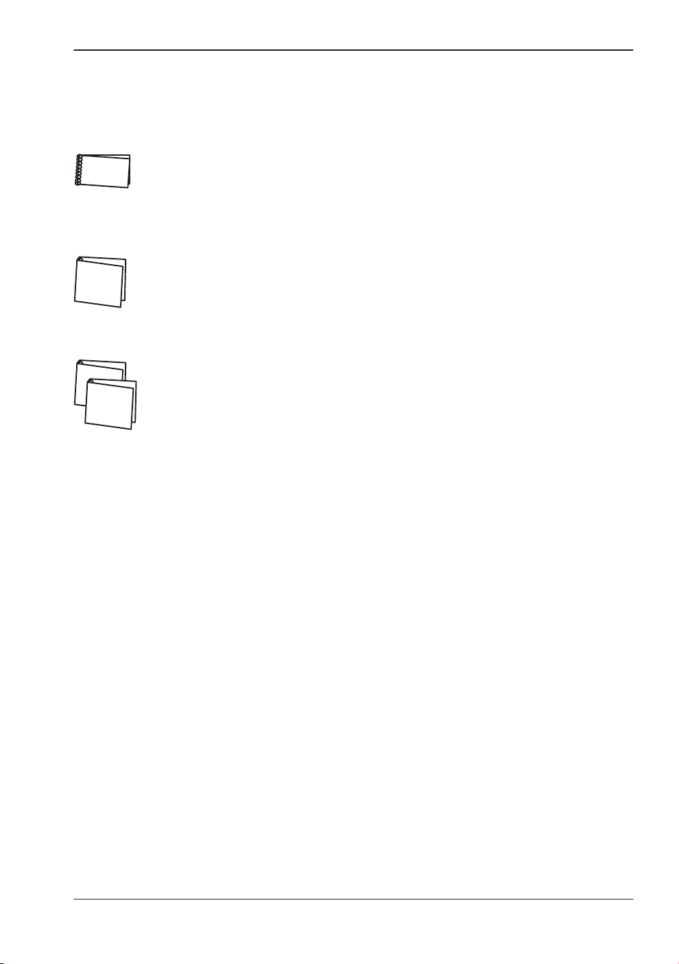
LOGIQt200 PRO Series Documentation consists of three
manuals:
S The Quick Start Guide (TRANSLATED) provides a
step-by-step description of the basic features and operation
of the LOGIQt200 PRO Series. It is intended to be used
in conjunction with the Basic User Manual in order to
provide the information necessary to operate the system
safely.
S The Basic User Manual (TRANSLATED) provides
information needed by the user to operate the system
safely. It describes basic functions of the system, safety
features, operating modes, basic
measurements/calculations, probes, user care and
maintenance.
S The Advanced Reference Manual (ENGLISH ONLY) is
intended for the trained, professional user. It contains all
the information found in the Quick Start Guide and Basic
User Manual, as well as information on options, advanced
customization techniques and data tables.
The LOGIQt200 PRO Series manuals are written for users
who are familiar with basic ultrasound principals and
techniques. They do not include sonography training or clinical
procedures.
LOGIQt200 PRO Series Basic Users Manual
2234813–100 Rev 1
3
Page 23

System Overview
Introduction
The LOGIQ200 PRO Series Ultrasound System is a high
performance and compact size ultrasound imaging system,
intended for general purpose applications.
The system provides image generation in B-Mode, M-Mode and
B/M-Mode with all transducer types. Digital architecture allows
maximum flexibility of all scanning modes and transducer types,
throughout the full spectrum of operating frequencies.
All transducers are precise solid state array devices, allowing
electronically controlled imaging with Convex, Micro-convex,
Sector and Linear probes. Use of solid state designs allows a
wide variety of scan parameters to be optimized including
focusing, scan control, spatial resolution, temporal resolution
and contrast resolution. The result is consistent generation of
finely detailed anatomical resolution with excellent dynamic
contrast tissue range and penetration.
The system display processor is highly versatile to produce the
optimal set of imaging parameters and display formats without
compromising important diagnostic information.
Versatile, yet easy to use, the LOGIQ200 PRO Series system
combines a wide variety of state-of-the-art operator features
without complicating operation. The operator can customize all
set-up parameters for a given mode, probe or clinical
application. Operator controls have been placed in a logical
clinical format. Two simultaneous probe connections allow
rapid switching electronically between probes without delaying
the examination.
The LOGIQ200 PRO Series System provides a total imaging
solution for today’s diverse ultrasound department needs, with
investment security through reliable upgrades, application
enhancements, and complete product support from GE.
4
LOGIQ200 PRO Series Basic Users Manual
2234813–100 Rev 1
Page 24

General Indications for Use
The LOGIQt200 PRO Series diagnostic ultrasound system is
intended for use in diagnostic ultrasound imaging using B, M,
B/M combination modes in the following areas:
S Fetal
S Abdomen
S Intraoperative
S Pediatric
S Small organs including breast, neck, chest, male and
female reproductive organs, limbs, and extremities
S Adult cephalic
S Neonatal cephalic
S Adult cardiac
S Pediatric cardiac
S Trans-vaginal
S Trans-rectal
System Overview
Contraindications
S Urology
The System is NOT intended for use in the following areas:
Ophthalmic use (or any use causing the acoustic beam to pass
through the eye).
LOGIQt200 PRO Series Basic Users Manual
2234813–100 Rev 1
5
Page 25

Who to Contact
Who To Contact
Who to Contact
For additional information or assistance, please contact your
local distributor or the appropriate support resource listed
below:
USA
GE Medical Systems TEL: (1) 800–437–1171
Ultrasound Service Engineering FAX: (1) 414–647–4090
4855 W. Electric Avenue
Milwaukee, WI 53219
Customer Answer Center TEL: (1) 800–682–5327 or
(1) 414–524–5698
CANADA
GE Medical Systems TEL: (1) 800–664–0732
Ultrasound Service Engineering
4855 W. Electric Avenue
Milwaukee, WI 53219
Customer Answer Center TEL: (1) 800–682–5327 or
(1) 414–524–5698
LATIN & SOUTH AMERICA
GE Medical Systems TEL: (1) 305–735–2304
Ultrasound Service Engineering
4855 W. Electric Avenue
Milwaukee, WI 53219
Customer Answer Center TEL: (1) 800–682–5327 or
(1) 414–524–5255
EUROPE
GE Ultraschall TEL: 0130 81 6370 toll free
Deutschland GmbH & Co. KG TEL: (49)(0) 212.28.02.208
Beethovenstrae 239 FAX: (49)(0) 212.28.02.28
Postfach 1 1 05 60
D–42655 Solingen
ASIA
GE Medical Systems Asia TEL: (81) 426–56–0033
Asia Support Center FAX: (81) 426–56–0053
67–4 Takakura cho, Hachiouji–shi
Tokyo, 192 JAPAN
6
LOGIQ200 PRO Series Basic Users Manual
2234813–100 Rev 1
Page 26

Who To Contact (cont’d)
AUSTRIA
GE GesmbH Medical Systems Austria TEL: 0660 8651 toll free
Prinz Eugen Strasse 8/8 FAX: +43 1 505 38 74
A–1040 WIEN TLX: 136314
BELGIUM
GE Medical Systems Benelux TEL: +32 0 3 320 12 11
Gulkenrodestraat 3 FAX: +32 0 3 320 12 59
B–2160 WOMMELGEM TLX: 72722
DENMARK
GE Medical Systems Danmark TEL: +45 45 51 00 55
Skovlytoften 4 FAX: +45 42 42 59 89
DK–2840 HOL TE
FRANCE
GE Medical Systems TEL: +33 1 46 10 01 30
738 rue Yves Carmen FAX: +33 1 46 10 01 20
F–92658 BOULOGNE CEDEX
GERMANY
GE Ultraschall TEL: 0130 81 6370 toll free
Deutschland GmbH & Co. KG TEL: (49)(0) 212.28.02.208
Beethovenstrae 239 FAX: (49)(0) 212.28.02.28
Postfach 1 1 05 60
D–42655 Solingen
Who to Contact
GREECE
GE Medical Systems Hellas TEL: +30 1 93 24 582
41, Nikolaou Plastira Street FAX: +30 1 93 58 414
G–171 21 NEA SMYRNI
ITALY
GE Medical Systems Italia TEL: +39 39 20 881
Via Monte Albenza 9 FAX: +39 39 73 37 86
I–20052 MONZA TLX: 3333 28
NETHERLANDS
GE Medical Systems Nederland B.V. TEL: +31 304 7971 1
Atoomweg 512 FAX: +31 304 11702
NL–3542 AB UTRECHT
POLAND
GE Medical Systems Polska TEL: +48 2 625 59 62
Krzywickiego 34 FAX: +48 2 615 59 66
P–02–078 WARSZAWA
LOGIQ200 PRO Series Basic Users Manual
2234813–100 Rev 1
7
Page 27

Who to Contact
Who to Contact (cont’d)
PORTUGAL
GE Medical Systems Portuguesa S.A. TEL: +351 2 2007696/97
Rua Sa da Bandeira, 585 FAX: +351 2 2084494
Apartado 4094 TLX: 22804
P–4002 PORTO CODEX
RUSSIA
GE VNIIEM TEL: +7 095 956 7037
Mantulinskaya UI. 5A FAX: +7 502 220 32 59
123100 MOSCOW TLX: 613020
SPAIN
GE Medical Systems España TEL: +34 1 676 4012
Hierro 1 Arturo Gimeno +34 1 676 4047
Poligono Industrial I FAX: +34 1 675 3364
E–28850 TORREJON DE ARDOZ TLX: 22384 A/B GEMDE
SWEDEN
GE Medical Systems TEL: +46 87 50 57 00
PO–BOX 1243 FAX: +46 87 51 30 90
S–16428 KIST A TLX: 12228
SWITZERLAND
GE Medical Systems (Schweiz) AG TEL: +41 41 425577
Sternmattweg 1 FAX: +41 41 421859
CH–6010 KRIENS
GEMED SU
CGRSWES
Manufacturer
TURKEY
GE Medical Systems Turkiye A.S. TEL: +90 212 75 5552
Mevluk Pehliran Sodak FAX: +90 212 211 2571
Yilmaz Han, No 24 Kat 1
Gayretteppe
IST ANBUL
UNITED KINGDOM
IGE Medical Systems TEL: +44 753 874000
Coolidge House FAX: +44 753 696067
352 Buckingham Avenue
SLOUGH
Berkshire SL1 4ER
SAMSUNG GE MEDICAL SYSTEMS
65–1, Sangdaewon–Dong, Chungwon–Ku, TEL: (82) 342–740–6114
Sungnam–Si,Kyunggi–Do FAX: (82) 342–746–9634
KOREA
8
LOGIQ200 PRO Series Basic Users Manual
2234813–100 Rev 1
Page 28

Manual Content
How This Book Is Organized
How This Book is Organized
The LOGIQt200 PRO Series User Manual is organized to
provide the information needed to start scanning right away.
Detailed information is also provided for more time-intensive
studies.
S Getting started. These sections give an overview of the
system to help the operator start scanning as soon as
possible.
S
Introduction.
contraindications for use, who to contact and how this
documentation is organized.
S
Safety
operation of the LOGIQt200 PRO Series system.
Information concerning indications/
. Important information concerning the safe
S
Preparing the System for Use.
system for use and a map of the control layout.
S
Preparing for an Exam.
information, select an exam category.
S Image optimization. These sections detail how to improve
image, trace, or spectral information.
S
Modes
. How to adjust and optimize B-Mode and
M-Mode imaging.
S
Scanning and Display Functions.
concerning Zoom, Freeze, Cine and Annotation
functions.
How to enter patient
How to prepare the
Information
LOGIQt200 PRO Series Basic Users Manual
2234813–100 Rev 1
9
Page 29

How This Book Is Organized
Manual Content (cont’d)
S Measurements and Reports. Shows how to do general
and exam category specific measurements and
calculations.
S
General Measurements and Calculations
on basic measurements for each mode.
S
Exam Categories.
S Recording Images. Explains the use of image archive and
peripheral options.
S Customizing your system. Shows how to customize the
system for your particular institution, clinic, or exam type.
S Probes and Biopsy. Provides intended uses,
specifications, care and maintenance, and biopsy capability
instructions for each probe.
S
Abdomen and Small Parts.
S
OB/GYN
S
Cardiology.
S
Urology.
.
. Emphasis
S User Maintenance. Provides information concerning
system specifications, warranties, error messages, user
diagnostics, bioeffects, quality assurance, system care and
assistance.
S Data Tables. Provides necessary data for reference.
S
Acoustic Output.
10
LOGIQt200 PRO Series Basic Users Manual
2234813–100 Rev 1
Page 30

How This Book Is Organized
Manual Format
Information has been arranged and provided to help find
information easily and quickly.
Finding information
Tables of Contents Locate topics in the main table of contents.
Tabs Chapter tabs are provided.
Headers/Footers The section name and page number appear on the outer
corners of every page.
References See also page references that are noted.
Index Meant for frequent and easy reference. Extensive tool that
presents ideas, topics, terms, titles, headings, and cross
references. Also, use it to find all entries of a like topic
throughout the manual.
2-Column Layout The right column contains text; the left column contains headers
and graphics to highlight the text.
Graphics Graphics provide a visual guide to the text when possible.
Turn rotary knobs to the left (counterclockwise) and right
(clockwise).
LOGIQ200 PRO Series Basic Users Manual
2234813–100 Rev 1
11
Page 31

How This Book Is Organized
Finding information (cont’d)
Move TGC slidepots to the left and right.
Move the Trackball around with the palm of a hand or
fingertips.
Notes Notes are set in
Icons Various icons highlight safety issues.
.
References References to other chapters appear in
Hints
Indicates precautions or prudent use recommendations that
should be used in the operation of the ultrasound system.
Scanning hints help save time.
italics
.
W ARNINGDANGER
CAUTION
italics
.
12
LOGIQt200 PRO Series Basic Users Manual
2234813–100 Rev 1
Page 32

Safety Precautions
Icon Description
Safety Precautions
Various levels of safety precautions may be found on the
equipment and different levels of concern are identified by one
of the following flag words which precede the precautionary
statement.
DANGER
W ARNING
CAUTION
Indicates that a specific hazard is known to exist which through
inappropriate conditions or actions will cause:
S Severe or fatal personal injury
S Substantial property damage.
Indicates that a specific hazard is known to exist which through
inappropriate conditions or actions may cause:
S Severe personal injury
S Substantial property damage.
Indicates that a potential hazard may exist which through
inappropriate conditions or actions will or can cause:
S Minor injury
S Property damage.
2
LOGIQt200 PRO Series Basic Users Manual
2234813–100 Rev 1
Page 33

Hazard Symbols
Icon Description
Icon Potential Hazard Usage Source
Safety Precautions
Potential hazards are indicated by the following icons:
Biological
Hazard
Electrical
Hazard
Moving
Hazard
Acoustic
Output
Hazard
Explosion
Hazard
S Patient/user infection due
to contaminated
equipment.
S Electrical micro-shock to
patient, e.g., ventricular
fibrillation initiated.
S Electrical macro-shock to
patient/user.
S Console, accessories or
optional storage devices
fall on patient, user, or
others.
S Collision with persons or
objects results in injury while
maneuvering or during
system transport.
S Injury to user from moving
the console.
S Patient injury or tissue
damage from ultrasound
radiation.
S Risk of explosion if used in
the presence of flammable
anesthetics.
S Cleaning and care
instructions
S Sheath and glove
guidelines
S Probes
S ECG
S Connections to back panel
S Moving
S Using brakes
S Transporting
S ALARA, the use of acoustic
output following the as low
a
s reasonably achievable
principle
S Flammable anesthetic
ISO 7000
No. 0659
Smoke
& Fire
Hazard
Non–
Ionizing
S Patient/user injury or
adverse reaction from fire or
smoke.
S Patient/user injury from
explosion and fire.
S Console failure, erratic
operation or output error
due to RF interference.
Radiation
Table 2–1. Potential Hazards
LOGIQt200 PRO Series Basic Users Manual
2234813–100 Rev 1
S Replacing fuses
S Outlet guidelines
S RF
IEC 878
No. 03-04
3
Page 34

Safety Precautions
Important Safety Considerations
Patient Safety
Related Hazards
W ARNING
Patient
identification
Diagnostic
information
The following sections (
Personnel Safety
aware of particular hazards associated with the use of this
equipment and the extent to which injury can occur if
precautions are not observed. Additional precautions may be
provided throughout the manual. The equipment user is
obligated to be familiar with these concerns and avoid
conditions that could result in injury.
The concerns listed can seriously affect the safety of patients
undergoing a diagnostic ultrasound examination.
Always include proper identification with all patient data and
verify the accuracy of the patient’s name or ID numbers when
entering such data. Make sure correct patient ID is provided on
all recorded data and hard copy prints. Identification errors
could result in an incorrect diagnosis.
Equipment malfunction or incorrect settings can result in
measurement errors or failure to detect details within the image.
The equipment user must become thoroughly familiar with the
equipment operation in order to optimize its performance and
recognize possible malfunctions. Applications training is
available through the local GE representative. Added
confidence in the equipment operation can be gained by
establishing a quality assurance program.
Patient Safety
) are intended to make the equipment user
, and
Equipment and
4
Mechanical
hazards
Damaged probes or improper use and manipulation of
intracavitary probes can result in injury or increased risk of
infection. Inspect probes often for sharp, pointed, or rough
surface damage that could cause injury or tear protective
barriers. Never use excessive force when manipulating
intracavitary probes. Become familiar with all instructions and
precautions provided with special purpose probes.
LOGIQ200 PRO Series Basic Users Manual
2234813–100 Rev 1
Page 35

Related Hazards (cont’d)
Safety Precautions
Electrical
Hazard
Acoustic
Output
Hazard
Training
A damaged probe can also increase the risk of electric shock if
conductive solutions come in contact with internal live parts.
Inspect probes often for cracks or openings in the housing and
holes in and around the acoustic lens or other damage that
could allow liquid entry. Become familiar with the probe’s use
and care precautions outlined in
Ultrasound energy, even at diagnostic levels, is capable of
damaging sensitive tissues if adequate precautions are not
followed. The wrong combination of equipment settings, probe
positioning, and tissue type can result in injury. Please become
thoroughly familiar with equipment controls. Acoustic output
concerns and their potential bioeffects are discussed in
Maintenance
Follow the principle of as low as reasonably achievable
(ALARA) when scanning a patient. During each ultrasound
examination, the clinical user is expected to weigh the medical
benefit of the diagnostic information obtained against the risk of
potential harmful effects. Once an optimal image is achieved
the need for increasing acoustic output or prolonging the
exposure cannot be justified.
It is recommended that all users receive proper training in
applications before performing them in a clinical setting. Please
contact the local GE representative for training assistance.
ALARA training is provided by GE Application Specialists.
.
Probes
.
User
LOGIQ200 PRO Series Basic Users Manual
2234813–100 Rev 1
5
Page 36

Safety Precautions
Equipment and Personnel Safety
Related Hazards
W ARNING
DANGER
Explosion
Electrical
Hazard
Hazard
This equipment contains dangerous voltages that are capable
of serious injury or death.
There are no user servicable components inside the console.
Refer all servicing to qualified service personnel only.
The concerns listed below can seriously affect the safety of
equipment and personnel during a diagnostic ultrasound
examination.
Risk of explosion if used in the presence of flammable
anesthetics.
To avoid injury:
S Do not remove protective covers. No user serviceable
parts are inside. Refer servicing to qualified service
personnel.
S To assure adequate grounding, connect the attachment
plug to a reliable (hospital grade) grounding outlet (having
equalization conductor
).
6
Smoke
& Fire
Hazard
S Do not place liquids on or above the console. Spilled liquid
may contact live parts and increase the risk of shock.
The system must be supplied from an adequately rated
electrical circuit. The capacity of the supply circuit must be as
specified in Chapter 3 of the LOGIQt200 PRO Series Service
Manual.
LOGIQt200 PRO Series Basic Users Manual
2234813–100 Rev 1
Page 37

Related Hazards (cont’d)
Safety Precautions
Biological
CAUTION
Hazard
For patient and personnel safety, beware of biological hazards
while performing invasive procedures. To avoid the risk of
disease transmission:
S Use protective barriers (gloves and probe sheaths)
whenever possible. Follow sterile procedures when
appropriate.
S Thoroughly clean probes and reusable accessories after
each patient examination and disinfect or sterilize as
needed. Refer to
instructions.
S Follow all infection control policies established by your
office, department or institution as they apply to personnel
and equipment.
Devices containing latex may cause severe allergic reaction in
latex sensitive individuals. USA customers should refer to the
FDA’s March 29, 1991 Medical Alert on latex products.
Probes
for probe use and care
LOGIQt200 PRO Series Basic Users Manual
2234813–100 Rev 1
7
Page 38

Safety Precautions
Device Labels
Label Icon Description
The following table describes the purpose and location of safety
labels and other important information provided on the
equipment.
Label/Icon Purpose/Meaning Location
Identification and Rating
Plate
Type/Class Label Used to indicate the degree of safety or
IP Code (IPX1) Indicates the degree of protection provided by
S Manufacturer’s name and address
S Date of manufacture
S Model and serial numbers
S Electrical ratings (Volts, Amps, phase, and
frequency)
protection.
the enclosure per IEC 529. IPX1 indicates drip
proof.
Equipment Type BF (man in the box symbol)
IEC 878-02-03 indicates B Type equipment
having a floating applied part.
Rear of console near power
inlet
Foot Switch
Probe connectors
Device Listing/
Certification Labels
“DANGER – Risk of
explosion used in...”
Equipment Type CF (heart in the box symbol)
IEC 878-02-05 indicate equipment having a
floating applied part having a degree of
protection suitable for direct cardiac contact.
Laboratory logo or labels denoting
conformance with industry safety standards
such as UL or IEC.
The system is not designed for use with
flammable anesthetic gases.
“CAUTION” The equilateral triangle is usually
used in combination with other symbols to
advise or warn the user.
Table 2–2. Label Icons
ECG connector and surgical
probes
Rear of console
Rear of console
Various
8
LOGIQt200 PRO Series Basic Users Manual
2234813–100 Rev 1
Page 39

Label Icon Description (cont’d)
Label/Icon Purpose/Meaning Location
“ATTENTION – Consult accompanying
documents” is intended to alert the user to
refer to the operator manual or other
instructions when complete information cannot
be provided on the label.
“CAUTION – Dangerous voltage” (the lightning
flash with arrowhead in equilateral triangle) is
used to indicate electric shock hazards.
Safety Precautions
Various
Various
“Mains OFF” Indicates the power off position of
the mains power switch.
“Mains ON” Indicates the power on position of
the mains power switch.
Indicates Main protective earth terminal Various
Front of system,
Main power switch
Front of system,
Main power switch
Table 2–2. Label Icons (cont’d)
LOGIQ200 PRO Series Basic Users Manual
2234813–100 Rev 1
9
Page 40

Safety Precautions
Classifications
*1. Class I EQUIPMENT
*2. Type BF EQUIPMENT
Type of protection against electric shock
Class I Equipment (*1)
Degree of protection against electric shock
Type BF Equipment (*2) (Except ECG)
Type CF Equipment (*3) (ECG Only)
Ordinary Equipment
Continuous Operation
EQUIPMENT in which protection against electric shock does
not rely on BASIC INSULATION only, but includes an earth
ground. This additional safety precaution prevents exposed
metal parts from becoming LIVE in the event of an insulation
failure.
TYPE B EQUIPMENT with an F-TYPE APPLIED P ART
TYPE B EQUIPMENT: EQUIPMENT providing a specified
degree of protection against electric shock, with particular
regard to allowable LEAKAGE CURRENT.
Patient leakage current
*3. Type CF EQUIPMENT
Patient leakage current
Normal Mode Single fault condition
Less than 100 mA Less than 500 mA
EQUIPMENT providing a degree of protection higher than that
for TYPE BF EQUIPMENT against electronic shock particularly
regarding allowable LEAKAGE CURRENTS, and having an
F–TYPE APPLIED P ART.
Normal Mode Single fault condition
Less than 10 mA Less than 50 mA
10
LOGIQ200 PRO Series Basic Users Manual
2234813–100 Rev 1
Page 41

*4. EMC (Electromagnetic Compatibility)
4.1 EMC Performance
All types of electronic equipment may characteristically cause
electromagnetic interference with other equipment, either
transmitted through air or connecting cables. The term EMC
(Electromagnetic Compatibility) indicates the capability of
equipment to curb electromagnetic influence from other
equipment and at the same time not affect other equipment with
similar electromagnetic radiation from itself.
This product is designed to fully comply with the EN60601–1–2
(IEC60601–1–2), Class A, which stipulates in medical electric
equipment EMC regulations, that Devices must be designed
and manufactured in such a way as to remove or minimize risks
connected with reasonably foreseeable environmental
conditions such as magnetic fields, external electronic
influences electrostatic discharge, pressure, temperature, or
variances in pressure and accerleration.
Class A equipments are allowed in domestic establishments
when used under the jurisdiction of a health care profession.
Safety Precautions
CAUTION
Proper installation following the service manual is required in
order to achieve the full EMC performance of the product.
The product must be installed as stipulated in 4.2, Notice upon
Installation of Product.
In case of issues related to EMC, please call your service
personnel.
Do not use the following devices near this equipment. Use of
these devices near this equipment could cause this equipment
to malfunction.
DEVICES NOT TO BE USED NEAR THIS EQUIPMENT
Devices which intrinsically transmit radio waves such as:
Cellular phone, radio transceiver, mobile radio transmitter,
radio-controlled toys, etc.
Keep power to these devices turned off when near this
equipment.
Medical staff in charge of this equipment is required to instruct
technicians, patients and other people who may be around this
equipment to fully comply with the above regulaion.
LOGIQ200 PRO Series Basic Users Manual
2234813–100 Rev 1
11
Page 42

Safety Precautions
Classifications (cont’d)
4.2 Notice upon Installation of Product
1. Use either power supply cords provided by GE Medical
Systems or ones designated by GE Medical Systems.
Products equipped with a power source plug should be
plugged into the fixed power socket which has the
protective grounding conductor. Never use any adaptor
or converter to connect with a power source plug (i.e.
three-prong-to-two-prong converter).
2. Locate the equipment as far away as possible from
other electronic equipment.
3. Be sure to use only the cables provided by or
designated by GE Medical Systems. Connect these
cables following the installation procedures (i.e. wire
power cables separately from signal cables).
4. Lay out the main equipment and other peripherals
following the installation procedures described in the
Option Installation manuals.
4.3 General Notice
1. Designation of Peripheral Equipment Connectable to
This Product.
The equipment indicated in
Peripherals
compromising its EMC performance.
Avoid using equipment not designated in the list.
Failure to comply with this instruction may result in poor
EMC performance of the product.
, can be hooked up to the product without
Peripherals, List of Optional
12
LOGIQ200 PRO Series Basic Users Manual
2234813–100 Rev 1
Page 43

Classifications (cont’d)
Safety Precautions
2. Notice against User Modification
Never modify this product. Unilateral user modification
may cause degradation in EMC performance.
Modification of the product includes:
a. Changes in cables (length, material, wiring, etc.)
b. Changes in system installation/layout
c. Changes in system configuration/components
d. Changes in securing system parts (cover
open/close, cover screwing)
3. Operate the system with all covers closed. If a cover is
opened for some reason, be sure to shut it before
starting/resuming operation.
Operating the system with any cover open may affect
EMC performance.
LOGIQ200 PRO Series Basic Users Manual
2234813–100 Rev 1
13
Page 44

Safety Precautions
5. Patient Environmental Devices
MOD Driver
Peripheral Device
(1) B/W Video Printer
Signals I/O Port
Power In
Imaging Probes
Front Panel
Signals I/O Port
Power Out
Probe
Ports
Power Cable with Protective Earth
Rear Panel
Physio–Signal
Signals I/O Port
Foot Switch
Connector
Power Out
ECG
Power In
Peripheral
Devices
(1) VCR
(2) B/W Video
Printer
(3) Multi Image
Camera
(4) Line Printer
InSite Modem
Signals I/O Port
Power In
Foot Switch
O
ECG Cable
Power Line (AC~)
Ground Line
14
Figure 2–1. Patient Environmental Devices
LOGIQ200 PRO Series Basic Users Manual
2234813–100 Rev 1
Page 45

Classifications (cont’d)
5.1 Acceptable Devices
The devices shown in Figure 2–1 are specified to be suitable for
use within the PATIENT ENVIRONMENT.
Safety Precautions
CAUTION
CAUTION
Do not connect any probes or accessories without approval by
GE.
Those listed in the “Peripherals” and “Assistance” have been
tested and verified to be compatible with the LOGIQ200 PRO
Series system.
5.2 Unapproved Devices
The user takes All Responsibility for connecting unapproved
devices.
If devices are connected without the approval of GE, the
warranty will be INVALID.
Any device connected to the LOGIQ200 PRO Series must
conform to one or more of the requirements listed below:
1. IEC 50, IEC 65, IEC 335, IEC 348, IEC 414, IEC 820,
IEC 950, IEC 1010–1, ISO 7767, ISO 8185, ISO 8359
or IEC 60601–1.
2. The devices shall be connected to PROTECTIVE
EARTH (GROUND).
LOGIQ200 PRO Series Basic Users Manual
2234813–100 Rev 1
15
Page 46

Safety Precautions
Acoustic Output
Controls Affecting Output
The potential for producing mechanical or thermal bioeffects is
influenced by the controls listed below (refer to 17).
Direct. The Acoustic Output control has the most significant
effect on Acoustic Output.
Indirect. Indirect effects may occur when adjusting the
controls listed on 17.
Always observe the output display for possible effects.
Best practices while scanning
Hints
.
WARNING
Acoustic
Output
Hazard
S Raise the Acoustic Output only after attempting image
optimization with controls that have no affect on Acoustic
Output, such as Gain and TGC.
NOTE: Refer to the Optimization section of the Mode chapters
for a complete discussion of each control.
Be sure to have read and understood control explanations for
each Mode intended to be used before attempting to adjust the
Acoustic Output control or any control that can affect Acoustic
Output.
Use the minimum necessary output to get the best diagnostic
image or measurement during an examination. Begin the exam
with the probe that provides an optimum focal depth and
penetration.
16
LOGIQt200 PRO Series Basic Users Manual
2234813–100 Rev 1
Page 47

Safety Precautions
Controls
Mode Control Affect Default Setting
All Acoustic Output Direct. Significant The middle setting is a factory preset
B Focus Comb Indirect. Minor Off.
B/M Depth (FOV) Indirect. Minor Probe-dependent operator preset.
Focal Zone Position
and Number
Zoom Indirect. Minor Off.
Indirect. Minor Probe-dependent system preset.
Table 2–3. Controls Affecting Acoustic Output
Acoustic Output Default Levels
In order to assure that an exam does not start at a high output
level, the LOGIQ200 PRO Series initiates scanning at a
reduced or default output level for each probe. The reduced
level takes effect when the system is powered on, a new patient
is entered or when changing probes.
determined to be a reasonable setting
for all exams. Use presets to set the
output preferred by scan mode and
exam combination.
Factory probe default settings are:
CBF CAE MTZ CZB LH
80% 80% 80% 80% 80%
LE LI LT LB LD
80% 80% 80% 80% 80%
CS 10L SY ERB 3Cb
80% 100% 80% 80% 80%
LOGIQ200 PRO Series Basic Users Manual
2234813–100 Rev 1
17
Page 48

Safety Precautions
Warning Label Locations
Overview
LOGIQ200 PRO Series warning labels are provided in eight
different languages. Each message is provided in English,
German, French, Italian, Portuguese, Spanish, Korean, and
Japanese.
Monitor Labels
For service personnel, a temporary label is placed on the
monitor face to warn not to move the monitor support arm
without the monitor attached. Figure 2–2 shows the actual
label.
18
Figure 2–2. Temporary Label Location
LOGIQ200 PRO Series Basic Users Manual
2234813–100 Rev 1
Page 49

Monitor Labels (cont’d)
Two caution labels are found on the top of the monitor. One
warns to only move the console with the monitor in its lowest
position, and not to push the console from the side; the second
warns not to place objects on the top of the monitor. Figure 2–3
shows the actual labels.
Safety Precautions
12
Figure 2–3. Caution Labels on Top of Monitor
LOGIQ200 PRO Series Basic Users Manual
2234813–100 Rev 1
19
Page 50

Safety Precautions
Console Labels
Labels found on the back of the console will be translated to the
eight languages or be specific to the region.
Radio Interference Caution Label
CAUTION
20
Defibrillator
Caution
Label
Figure 2–4. Console Label Location
This is only for “FUNCTIONAL GROUNDING”, NOT
“PROTECTIVE EARTH”.
LOGIQ200 PRO Series Basic Users Manual
2234813–100 Rev 1
Page 51

Regulatory Labels
(America, Mexico, Canada, Brazil)
MADE FOR GE MEDICAL SYSTEMS
MILW AUKEE, WISCONSIN BY
For USA
Canada,
Mexico
SAMSUNG GE MEDICAL SYSTEMS
MODEL 2270969
SERIAL.
MANUFACTURED
VOLTS : 120Vac ~ 1 PHASE
POWER : 500VA
FREQUENCY : 60HZ
DESC, LOGIQ 200PRO
KOREA
CLASS 1
Safety Precautions
MADE FOR GE ME DICAL SYSTEMS
MILW AUKEE, WISCONSIN BY
For Brazil
SAMSUNG GE MEDICAL SYSTEMS
MODEL 2270970
SERIAL.
MANUFACTURED
VOLTS : 220–240Vac ~ 1 PHASE
POWER : 500VA
FREQUENCY : 50HZ
DESC, LOGIQ 200PRO
KOREA
CLASS 1
Figure 2–5. Regulatory Label Location
(America, Canada, Mexico, Brazil)
LOGIQ200 PRO Series Basic Users Manual
2234813–100 Rev 1
21
Page 52

Safety Precautions
Regulatory Labels (European Systems)
MODEL NUMBER : 2270968
MANUFACTURED
LOCATION:SAMSUNG GE MEDICAL
S.N. :
VOLT : 220–240Vac ~
AMP. LONG TERM : 2.1A
KVA : 0.5kVA
PHASE : 1
DESC. : LOGIQ 200PRO
SYSTEMS
KOREA
CISPR 11 / EN 55011
CLASS : A GROUP : 1
CLASSE : A GROUPE : 1
Figure 2–6. Regulatory Label Location (European)
Class1/Classe1
22
LOGIQ200 PRO Series Basic Users Manual
2234813–100 Rev 1
Page 53

Safety Precautions
Regulatory Labels (Sweden, Greece, Turkey, Russia, Denmark)
MODEL NUMBER : 2270968
MANUFACTURED
LOCATION:SAMSUNG GE MEDICAL
S.N. :
VOLT : 220–240Vac ~
AMP. LONG TERM : 2.1A
KVA : 0.5kVA
PHASE : 1
DESC. : LOGIQ 200PRO
SYSTEMS
KOREA
CISPR 11 / EN 55011
CLASS : A GROUP : 1
CLASSE : A GROUPE : 1
Figure 2–7. Regulatory Label Location
(Sweden, Greece, Turkey, Russia, Denmark)
Class1/Classe1
LOGIQ200 PRO Series Basic Users Manual
2234813–100 Rev 1
23
Page 54

Site Requirements
Introduction
Site Requirements
.
Only qualified physicians or sonographers should perform
ultrasound scanning on human subjects for medical diagnostic
reasons. Request training, if needed.
Do not attempt to install the system alone. General Electric,
Affiliate, or Distributor Field Engineers and Application
Specialists will install and setup the system.
Perform regular preventive maintenance. Refer to
Maintenance
Maintain a clean environment. Turn off the system before
cleaning the unit. Refer to
cleaning instructions.
Never set liquids on the unit to ensure that liquid does not drip
into the control panel or unit.
Ensure that unauthorized personnel do not tamper with the unit.
chapter for maintenance instructions.
User Maintenance
User
chapter for
2
LOGIQt200 PRO Series Basic Users Manual
2234813–100 Rev 1
Page 55

Before the system arrives
NOTICE
This medical equipment is approved, in terms of the prevention
of radio wave interference, to be used in hospitals, clinics and
other institutions which are environmentally qualified. The use
of this equipment in an inappropriate environment may cause
some electronic interference to radios and televisions around
the equipment. Proper handling of this equipment is required in
order to avoid such trouble according to the operator and
service manuals. This equipment can be used in residential
areas only under the supervision of physicians or qualified
technicians.
Ensure that the following is provided for the new system:
S A separate power outlet with a 15 amp circuit breaker for
120 VAC (USA) or 10 amp circuit breaker for 220–240 VAC
(Europe, Latin America).
S Take precautions to ensure that the console is protected
from electromagnetic interference.
Site Requirements
Precautions include:
S Operate the console at least 15 feet away from motors,
typewriters, elevators, and other sources of strong
electromagnetic radiation.
S Operation in an enclosed area (wood, plaster or
concrete walls, floors and ceilings) help prevent
electromagnetic interference.
S Special shielding may be required if the console is to be
operated in the vicinity of Radio broadcast equipment.
LOGIQt200 PRO Series Basic Users Manual
2234813–100 Rev 1
3
Page 56

Site Requirements
Environmental Requirements
The system should be operated, stored, or transported within
the parameters outlined below. Refer to Table 3–1.
Operational Storage Transport
Temperature
Humidity
Pressure
Table 3–1. System Environmental Requirements
10_- 40_ C
50_- 104_ F
5 ~ 90 % RH 5 ~ 90 % RH 5 ~ 90 % RH
700-1060hPa 700-1060hPa 700-1060hPa
–10_- 60_ C
14_- 140_ F
–40_- 60_ C
–40_- 140_ F
4
LOGIQt200 PRO Series Basic Users Manual
2234813–100 Rev 1
Page 57

Console graphics
Console Overview
Console Overview
The followings are illustrations of the console :
1
2
4
5
Figure 3–1. LOGIQ200 PRO Series System
1. Black & White monitor 2. Keyboard
3. Release Button 4. B/W Page Printer (Option)
5. Power On switch 6. Probe Holder
7. MOD Driver (Option)
3
6
7
LOGIQ200 PRO Series Basic Users Manual
2234813–100 Rev 1
5
Page 58

Console Overview
Console graphics (cont’d)
1
2
Figure 3–2. LOGIQ200 PRO Series System
1. Rear Handle 2. Rear Panel
6
LOGIQ200 PRO Series Basic Users Manual
2234813–100 Rev 1
Page 59

Storage areas
Console Overview
Several convenient storage areas are provided within the
console as shown in Figure 3–3. Use them to store probe
cables, accessories, etc.
1
1
1
Figure 3–3. Storage Areas
1. Storage Area
LOGIQ200 PRO Series Basic Users Manual
2234813–100 Rev 1
7
Page 60

Console Overview
Peripheral/Accessory Connector Panel
LOGIQ200 PRO Series peripherals and accessories can be
properly connected using the rear connector panel located
behind the rear console. Only the B/W Page Printer (UP-890)
can be connected to the front accessory panel.
Located on the connector panel are video input and output
connections, recorder/camera expose connectors, foot switch
connector, power connectors, SCSI bus control and service
tools connections.
CAUTION
CAUTION
Each outer (case) ground line of peripheral/accessory
connectors are Earth Grounded.
Signal ground lines are Not Isolated, except the Service Port.
All of the signal lines (including the signal ground) of the
Service Port are Isolated.
Service
Figure 3–4. Service Port
Use only approved probes, peripherals or accessories.
Refer to the
information.
Recording Images
chapter of this manual for more
8
LOGIQ200 PRO Series Basic Users Manual
2234813–100 Rev 1
Page 61

Peripheral/Accessory Connector Panel (cont’d)
Console Overview
115V 1.7A Max
including front panel
100V 2.0A Max
including front panel
220–240V 0.8A Max
including front panel
Figure 3–5. Peripheral/Accessory Connector Panel
LOGIQ200 PRO Series Basic Users Manual
2234813–100 Rev 1
9
Page 62

Console Overview
Foot Switch (option)
Freeze
Foot Switch
An optional Foot Switch may be used as an alternative to the
Freeze control to:
S Freeze a real-time image.
Only use the recommended foot switch.
The Foot Switch connection is located at the back of the
console on the right-hand side of the back panel.
Store the Foot Switch in the storage compartment located at the
front of the console, below the keyboard.
1
2
10
Figure 3–6. Foot Switch Storage and Connectors
1. Foot Switch Connector
2. Foot Switch Storage Area
LOGIQt200 PRO Series Basic Users Manual
2234813–100 Rev 1
Page 63

System Positioning/Transporting
Moving the System
System Positioning/Transporting
When moving or transporting the system, follow the precautions
below to ensure the maximum safety for people, the system,
and other equipment.
Before moving the system:
1. Turn the System power switch OFF.
2. Unplug the power cord.
3. All cables from off-board peripheral devices (IIE
camera, external printer, VTR, etc.) must be
disconnected from the console.
4. Ensure that no loose items are left on the console.
5. Loop the cord around the handle on the back of the
system or wrap the cord in a bundle and store it in the
front storage area. To prevent damage to the power
cord, DO NOT pull excessively on the cord or make
sharp bends while wrapping.
6. Connect all probes to be used while off site. Ensure
that probe cables are out of the way from the wheels
and not protruding beyond the console.
7. Store all other probes in their original cases or in soft
cloth or foam to prevent damage.
8. Store sufficient gel and other essential accessories in
the provided space.
9. Adjust the monitor to its lowest position possible.
Ensure that the monitor arm is locked in place.
10. Unlock the front wheels.
LOGIQ200 PRO Series Basic Users Manual
2234813–100 Rev 1
11
Page 64

System Positioning/Transporting
Moving the System (cont’d)
When moving the system:
1. Take extra care when moving the system long
distances and on inclines. Ask for help if necessary.
.
.
CAUTION
NOTE: Wheel chair ramps are usually less than five degrees.
Avoid ramps that are steeper than ten degrees to avoid
tipping over the
Utilize additional care and personnel when moving on
steep incline (>5°) or loading into a vehicle for
transport.
2. Always use the rear handle to move the system.
NOTE: DO NOT attempt to move the console using any cables
or fixtures, such as the probe connectors.
3. Use the brake, located on the bottom of the system in
the front, when necessary.
4. Do not let the system strike walls or door frames.
5. Use extra care when crossing door or elevator
thresholds.
6. Once the destination is reached, lock the wheels.
The system weighs approximately 76 kg (168 lbs). To avoid
possible injury and equipment damage:
S Be sure the pathway is clear.
S Limit movement to a slow careful walk.
system.
12
LOGIQt200 PRO Series Basic Users Manual
2234813–100 Rev 1
Page 65

Transporting the System
Use extra care when transporting the system using vehicles. In
addition to the instructions used when moving the system (refer
to
11
1. Only use vehicles that are designed for transport of the
2. Load and unload the system to a vehicle parked on a
3. Ensure that the transporting vehicle can handle the
4. Ensure that the load capacity of the lift (a minimum of
5. Ensure that the lift is in good working order.
6. Secure the system while it is on the lift so that it cannot
System Positioning/Transporting
), do the following:
LOGIQt200 PRO Series system.
level surface.
weight of the system plus the passengers.
76 kg (168 lbs) is recommended) is capable of handling
the weight of the system.
roll. Use either wood chocks, restraining straps, or
other similar types of constraints. Do not attempt to
hold it in place by hand.
.
WARNING
.
NOTE: Strap the system below its handle so that the system
does not break loose.
Never ride on the lift with the system. A person’s
weight coupled with the weight of the system may
exceed the load capacity of the lift.
7. Employ two to three persons to load and unload safely
from a vehicle.
8. Load the unit aboard the vehicle carefully and over its
center of gravity. Keep the unit still and upright.
NOTE: Do not lay the unit down.
9. Ensure that the system is firmly secured while inside
the vehicle. Any movement, coupled with the weight of
the system, could cause it to break loose.
10. Secure system with straps or as directed otherwise to
prevent motion during transport.
11. Prevent vibration damage by driving cautiously. Avoid
unpaved roads, excessive speeds, and erratic stops or
starts.
LOGIQt200 PRO Series Basic Users Manual
2234813–100 Rev 1
13
Page 66

System Positioning/Transporting
Wheels
.
Front wheels The front wheels swivel, pivot, and lock.
Back wheels The back wheels swivel and pivot but do not lock (Back wheels
Setting the lock
Examine the wheels frequently for any obvious defects that
could cause them to break or bind.
are optional depending on configuration).
To engage the wheel lock:
Press down on the lock pedal (located at the front of
the wheels). The pedal remains depressed.
To release the lock:
Press down on the pedal again. The pedal returns to
its normal position.
14
LOGIQt200 PRO Series Basic Users Manual
2234813–100 Rev 1
Page 67

Powering On the System
Connecting and Using the System
To connect the system to the electrical supply:
1. Ensure that the wall outlet is of the appropriate type.
2. Make sure that the power switch is turned off.
3. Unwrap the power cable. Make sure to allow sufficient
slack in the cable so that the plug is not pulled out of
the wall if the system is moved slightly.
4. Push the power plug securely into the wall outlet.
Powering On the System
W ARNING
Plug and Outlet Configuration
To avoid risk of fire, the system power must be supplied from a
separate, properly rated outlet. See Local Site Requirements,
Before the system arrives on 3 for rating information.
The system is supplied with an attachment plug. Under no
circumstances should this plug be altered, changed, or adapted
to a configuration rated less than specified. Never use an
extension cord or adapter plug.
To help assure grounding reliability, connect to a “hospital
grade” or “hospital only” grounded power outlet.
120 VAC, 1000 VA
(USA)
Figure 3–7. Example Plug and Outlet Configurations
220–240 VAC, 1000 VA
Plug and Outlet Configuration
(Europe)
LOGIQ200 PRO Series Basic Users Manual
2234813–100 Rev 1
15
Page 68

Powering On the System
Acclimation Time
After being transported, the system requires one hour for each
2.5_ increment its temperature is below 10_ C or above 40_ C.
_ C
_ F
hours
60 55 50 45 40 35 30 25 20 15 10
140 131 122 113 104 95 86 77 68 59 50
_ C
_ F
hours
41 32 23 14 5 –4 –13 –22 –31 –40
Power On
CAUTION
8 6 4 2 0 0 0 0 0 0 0
5 0 –5 –10 –15 –20 –25 –30 –35 –40
2 4 6 8 10 12 14 16 18 20
Table 3–2. System Acclimation Time Chart
The Power switch is located on the front of the console next to
the Probe Connectors. Press the top portion of this switch to
turn the power on.
16
I
Illustration 1. Location of Power Switch
LOGIQt200 PRO Series Basic Users Manual
2234813–100 Rev 1
Page 69

Power Up Sequence
Powering On the System
S The monitor and console power indicator light up.
S The system is initialized. During this time:
S One beep sounds during the sequence.
S All LEDs on the keyboard light.
.
Hints
.
Power Off
NOTE: If errors occur, an error message appears at the bottom
of the screen. See User Maintenance, Troubleshooting
for more information.
If problems occur, freeze the image and take a picture
for reference. This will help if there is a need to call for
service.
S Probes are initialized for immediate operation.
NOTE: If no probes are connected, the system goes into
standby mode.
S Peripheral devices are activated on power up.
After initialization has been completed, the system is in B-Mode
and ready for imaging. Refer to
instructions.
When switching off the system:
S Press the bottom portion (O) of the power switch.
S Disconnect the probes.
Basic Scan
for scanning
Clean or sanitize all probes as necessary. Store them in
their shipping cases to avoid damage.
LOGIQt200 PRO Series Basic Users Manual
2234813–100 Rev 1
17
Page 70

Adjusting the Display Monitor
Adjusting the Display Monitor
Rotate, tilt, raise and lower the monitor
The monitor position can be adjusted for easy viewing.
S The monitor can be rotated around it’s central pivot point.
S The monitor can be tilted for the optimum viewing angle.
S The monitor arm can be raised or lowered for the best
viewing height.
CAUTION
Figure 3–8. Monitor Movement
Monitor height adjustment requires the release of the locking
mechanism. After an adjustment is made, ensure that the
mechanism is locked to prevent unexpected motion.
When moving the LOGIQt200 PRO Series system, lower the
monitor to its lowest possible position to improve stability.
18
LOGIQt200 PRO Series Basic Users Manual
2234813–100 Rev 1
Page 71

Brightness and Contrast
Adjusting the monitor’s contrast and brightness is one of the
most important factors for proper image quality. If these
controls are set incorrectly, the Gain, TGC, Dynamic Range and
even Acoustic Output may have to be changed more often than
necessary to compensate.
The proper setup displays a complete gray scale. The lowest
level of black should just disappear into the background and the
highest white should be bright, but not saturated.
To adjust the Brightness and Contrast:
1. Turn on the LOGIQ200 PRO Series and display a
2. Access the Brightness/Contrast controls by rotating the
3. Rotate Brightness and Contrast knobs to minimum
4. Increase the Brightness until the background or
Adjusting the Display Monitor
gray scale image with a variety of echo levels.
knob on the left side of the display screen.
(counterclockwise).
monitor raster is just one shade above black.
5. Increase the Contrast to display the complete or
desired range of gray shades.
LOGIQ200 PRO Series Basic Users Manual
2234813–100 Rev 1
19
Page 72

Adjusting the Display Monitor
Brightness and Contrast (cont’d)
Generally speaking, do not change the controls once they have
been set. Once set, the display then becomes the reference for
the hard copy device(s).
.
.
NOTE: After readjusting the monitor’s Contrast and Brightness,
readjust all preset and peripheral settings.
1
2
Figure 3–9. Brightness and Contrast
1. Brightness 2. Contrast
NOTE: Monitor degaussing (demagnetizing) is done
automatically when the system is turned on.
20
LOGIQt200 PRO Series Basic Users Manual
2234813–100 Rev 1
Page 73

Introduction
Probes
Probes
Only use approved probes.
All imaging probes can be plugged into any of the two standard
probe ports.
For more
information
Refer to
Connecting the Probe
Probes can be connected at any time, regardless of whether
the console is powered on or off.
To connect a probe:
CAUTION
Probes and Biopsy
1. Place the probe’s carrying case on a stable surface and
open the case.
2. Carefully remove the probe and unwrap the probe cord.
3. DO NOT allow the probe head to hang free. Impact to
the probe head could result in irreparable damage.
chapter for more information.
Figure 3–10. Connecting a Probe
LOGIQ200 PRO Series Basic Users Manual
2234813–100 Rev 1
21
Page 74

Probes
Connecting the Probe (cont’d)
4. Align the connector with the probe port and carefully
push into place.
5. Pressing the clamshell gently and completely, turn the
connector locking handle clockwise or counter
clockwise to secure the probe connector. Locking
method is different depending on the type of a probe
refer to Figure 3–11.
.
NOTE: Press clamshell to push the copper spring completely
and lock the connector simultaneously.
6. Carefully position the probe cord so that it is free to
move and is not resting on the floor.
lock
unlock
22
UNLOCK
Figure 3–11. Locking a Probe Connector
LOCK
LOGIQt200 PRO Series Basic Users Manual
2234813–100 Rev 1
Page 75

Activating the Probe
To activate a probe:
The probe activates in the currently selected operating mode.
The probe’s default settings for the mode and selected
application are used automatically.
Storing the Probe
It is recommended that all probes be stored in the carrying case
provided.
Probes
Press the Probe Select key.
Probe Select1 Probe Select2
12
Figure 3–12. Probe Select Key
To store a probe:
1. First place the probe connector into the carrying case.
2. Carefully wind the cable into the carrying case.
3. Carefully place the probe head into the carrying case.
DO NOT use excessive force or impact the probe head.
LOGIQ200 PRO Series Basic Users Manual
2234813–100 Rev 1
23
Page 76

Probes
Deactivating the Probe
When deactivating the probe, the probe is automatically placed
in standby mode.
To deactivate a probe:
Probes can be disconnected at any time, regardless of whether
the console is powered on. However, the probe should not be
selected as the active probe.
To disconnect a probe:
1. Press the Freeze key.
2. Gently wipe the excess gel from the face of the probe.
3. Carefully slide the probe around the right side of the
keyboard, toward the probe holder.
4. Ensure that the probe is placed gently in the probe
holder.
1. Move the probe locking handle counterclockwise.
2. Pull the probe and connector straight out of the probe
port.
3. Carefully slide the probe and connector away from the
probe port and around the right side of the keyboard.
4. Ensure the cable is free.
5. Be sure that the probe head is clean before placing the
probe in its storage box.
24
LOGIQ200 PRO Series Basic Users Manual
2234813–100 Rev 1
Page 77

Control Panel Map
Operator Controls
Operator Controls
Controls are grouped together for ease of use. For in-depth
information on using the controls, refer to the
chapter.
Scan Modes
Figure 3–13. Keyboard Layout
LOGIQ200 PRO Series Basic Users Manual
2234813–100 Rev 1
25
Page 78

Operator Controls
Control Panel Map (cont’d)
S Patient Information. See 4–2.
S Probe See 23.
S Preset. These keys can be programmed through the Setup
menu to establish a set of start up parameters.
S TGC Controls. These controls are used to adjust the Time
Gain Compensation applied to the received signal.
S Measurements and Annotations. These controls are
used to make specified measurements on the image or to
annotate the image display.
S Mode, Display and Record. These controls are used to
designate display modes, image orientation, gain, freeze,
and record (print).
S Keyboard. The keyboard is used for patient data entry,
image annotation and other special functions.
Preset Keys
Preset1 Preset2
.
Figure 3–14. Preset Keys
The Preset keys are used to store user defined setup.
These controls compensate for echo attenuation as depth
increases.
.
21
26
LOGIQt200 PRO Series Basic Users Manual
2234813–100 Rev 1
Page 79

Measurement and Annotation
This group of controls performs various functions related to
making measurements, annotating and adjusting the image
information.
Operator Controls
Comment
Body Pattern
Ellipse
Set
The Comment key enables the image text editor and displays
the annotation library in the Setup menu. After the Comment
key is pressed, text can be added through the Setup Menu
comment library or by typing comments from the alphanumeric
keyboard. Turning off the cursor can be done by pressing the
Set key. Pressing the Clear key will erase all comments.
The Body Pattern key enables the pattern on the screen. For
more details refer to 6–15.
The Measurement key is used in all types of basic
measurements.
The Ellipse Up key is used to activate the ellipse measurement
function after the first distance measurement has been set.
The Set key is used for various functions, but is generally used
to fix or finish an operation (i.e. to fix a measurement cursor or
position in zoom).
LOGIQ200 PRO Series Basic Users Manual
2234813–100 Rev 1
27
Page 80

Operator Controls
Measurement and Annotation
Clear
Zoom
Focus Rotation
ECG Gain
The Clear key is generally used to erase or exit functions such
as annotations/comments, measurements and zoom.
Press the Zoom key to activate the zoom function. For more
details refer to 6–2.
The Focus/Rotation, ECG Gain knob is used to rotate the
probe position indicator in the body pattern function. Otherwise,
the knob is used to change the focus position like the Focus
keys on the keyboard. This knob is also used to adjust the
receive gain of the ECG signal.
The Trackball is used with almost every key function in this
group. Trackball control depends on the last key function
pressed.
28
LOGIQ200 PRO Series Basic Users Manual
2234813–100 Rev 1
Page 81

Mode, Display and Record
This group of controls provides various functions relating to the
display mode, display orientation, freeze, gain and cine scroll.
The Mode Controls select the desired display mode or
combinations of display modes.
During dual display modes the L and R keys activate the Left or
B Mode
Right displayed image.
Operator Controls
L
Increase Decrease
R
Image Recall
Image Memory
Reverse
The Depth knob controls the image display depth. Clockwise
rotation decreases display depth. Counterclockwise rotation
increases display depth.
The Image Recall key displays a menu of the images stored in
memory. After pressing Image Recall, select the desired
image from the Menu for display.
The Image Memory key stores the current frozen displayed
image in system image memory.
Maximum number of images is 10.
All images are erased when the New Patient key is pressed or
there is a loss of system power.
The Reverse key toggles the left/right orientation of the scan
image.
LOGIQ200 PRO Series Basic Users Manual
2234813–100 Rev 1
29
Page 82

Operator Controls
Mode, Display and Record (cont’d)
The Record 1 and Record 2 keys are used to activate/print the
designated recording device (i.e. video page printer,
multi-image camera, or image archive option).
Record1
Record2
The Freeze key is used to stop the acquisition of ultrasound
data and freeze the image in system memory.
Pressing Freeze a second time continues live image
acquisition.
The B/M Gain/Cine Scroll knob control performs a dual
function. During B-Mode, it controls the gain of the displayed
echoes. During M-Mode, it controls the gain of the displayed
timeline echoes.
B.M.Gain
FWBW
Cine Scroll
When the image is frozen it controls scrolling forwards and
backwards through the Cine loop images in temporary storage.
30
LOGIQ200 PRO Series Basic Users Manual
2234813–100 Rev 1
Page 83

Keyboard
Operator Controls
The keyboard has standard alphanumeric keys available along
with some special functions.
.
Esc
Ctrl
BackSpace
Return
Tab
Shift
NOTE: The Cursor Home key is also used as a Focus
Combination Key to activate the Focus Combination function.
The Escape key is used to exit or cancel B mode, M mode, B/M
mode, Setup mode, Archive mode, Report Page, New Patient
and Patient ID menu.
Control is used in conjunction with other keys to activate
special keyboard functions.
Back Space is used to delete previous characters while
annotating.
Return is used to move to the next line of annotation.
Tab is used to move forward or backwards through the text one
word at a time or eight characters at a time, depending on the
keyboard tab preset.
Shift (Green) is used to activate the special characters
highlighted in green on the keys located on the right side of the
keyboard. See 6–13 for details.
Shift (Blue) is used to activate the special characters
Shift
CapsLock
LOGIQt200 PRO Series Basic Users Manual
2234813–100 Rev 1
highlighted in blue on the keys in the middle of the keyboard.
See
6–13
for details.
Caps Lock locks all alpha characters in the upper case mode.
The keyboard has several function keys available along with
alphanumeric functions.
31
Page 84

Operator Controls
Special Key Function
The keyboard has several function keys along with the
alphanumeric functions.
Report Page
Archive Menu
Setup Menu
Dyn Range
!
1
Map
#
3
Frame Avg
The Report Page key is used to display the report format of
each exam category.
The Archive Menu key is used to display the Archive Menu.
The Setup Menu key is used to display the Setup Menu.
Dyn Range keys are used to control Dynamic Range.
@
2
The Map keys are used to change Gray Scale Map.
$
4
The Frame Avg key is used to enhance the frame averaging
function.
%
5
32
LOGIQ200 PRO Series Basic Users Manual
2234813–100 Rev 1
Page 85

Special Key Function (cont’d)
Operator Controls
Edge Enhc
^
6
Multi Freq
&
7
Sweep Speed
9
Biopsy
Ext.Video
The Edge Enhc key is used to enhance the edge enhancement
function.
The Multi Freq key is used to enhance the penetration function.
The Sweep Speed key is used to choose Sweep Speed.
The Biopsy key is used to activate the biopsy function.
The Ext Video key is used to display the External Video on the
LOGIQ200 PRO Series screen.
LOGIQ200 PRO Series Basic Users Manual
2234813–100 Rev 1
33
Page 86

Operator Controls
Special Key Function (cont’d)
The four Arrow keys are used to move the cursor in the
Calculation mode. The two right/left keys are Scan Width keys
that are used to control Scan Width. The two up/down keys are
Scroll keys that are used to scroll the display up or down in the
image mode.
The Calculation keys are used to activate the calculation
menus.
The ATO key is used to change the ATO.
Scan Width
Calculation
Scroll
Focus
Cursor Home
Combi Focus
The Focus keys are used to change the focus position.
The Cursor Home key brings the alphanumeric cursor to the
very upper left corner of the available field. This key is also
used to activate combi focus.
34
LOGIQ200 PRO Series Basic Users Manual
2234813–100 Rev 1
Page 87

User Defined Keys
Operator Controls
User Define1
User Define2 User Define3
User Define4
Desired functions can be assigned to these keys (User Define 1
~4) in the User Define Category and Key Setup menu (page 10
of 11). Refer to 13–47 for more information.
LOGIQ200 PRO Series Basic Users Manual
2234813–100 Rev 1
35
Page 88

Beginning an Exam
Introduction
Beginning an Exam
Begin an exam by entering new patient information.
The operator should enter as much information as possible,
such as:
S Exam category
S Patient name
S Patient ID
S Comments
S Other patient demographic information
The patient’s name and ID number is retained with each
patient’s image and transferred with each image during
archiving or hard copy printing.
Beginning a New Patient
New Patient
The New Patient key should be pressed at the beginning of
each patient study. Pressing this key automatically erases all
patient data, annotations, measurements, calculations and
summary report pages. A preset parameter, in the Patient
Entry Setup menu, can be set to prompt the user if they wish to
erase all data or not.
2
LOGIQt200 PRO Series Basic Users Manual
2234813–100 Rev 1
Page 89

Beginning a New Patient (cont’d)
Enter patient data with the alphanumeric keyboard.
The Setup Menu automatically defaults to the last exam preset
top menu when New Patient is pressed. A diagnostic region
can be selected from the Preset sub-menus to provide a
suitable starting point for system scan parameters.
Beginning an Exam
.
CAUTION
NOTE: Oper ID and Ref MD will not be erased.
To avoid patient identification errors, always verify the
information with the patient. Make sure the correct patient
identification appears on all screens and hard copy prints.
The Patient Entry Menu appears on the display monitor.
[PATIENT ENTRY MENU]
EXAM CATEGORY SELECTION : 2
1: RAD/ABDOMEN 2: OBSTETRICS 3: GYNECOLOGY
4: CARDIOLOGY 5: UROLOGY 6: SMALL PARTS
7: USER DEFINE1 8: USER DEFINE2
PT NAME :
PT ID :
NOTE :
Oper ID :
EXAM INFORMATION
AGE: yrs
PREGNANCY ORIGIN DATA SELECTION : 3
( 1: LMP 2: BBT 3: EDD 4: GA )
LMP :yy/mm/dd
EDD ? : yy/mm/dd BBT :yy/mm/dd
EDD :yy/mm/dd
GA : # W # D
GRAVIDA : ## PARA : ## AB : ## ECTOPIC : #
Ref MD:
Enter Past Exam Data : Sub menu Sub
COMMENT :
EXIT
Figure 4–1. Patient Entry Menu
NOTE: The question “Do you really want to change patient?”
.
LOGIQt200 PRO Series Basic Users Manual
2234813–100 Rev 1
can be enabled or disabled in Patient Entry Setup.
3
Page 90

Beginning an Exam
Beginning a New Patient (cont’d)
The first Data Entry field is presented in reversed display, with
the selected cursor in position for the first character to be
entered.
S Select from 8 examination categories :
Radiology/Abdominal, Obstetrics, Gynecology , Cardiology,
Urology, Small Parts, User Define1 and User Define2. The
category should be selected before the start of the
examination.
S The patient information input menu changes depending on
the Category. Information pertinent to the selected exam
category appears in an abbreviated menu.
S The USER DEFINE1 and 2 fields (#7, 8) can be input (15
characters maximum) in the User Define Category and Key
Setup, Category name edit menu. Refer to 13–47.
S To navigate through the Patient Entry Menu, use the
Return key or the Trackball to move the cursor.
S Input the patient name (29 characters maximum).
.
S Input ID number (14 characters maximum).
S Input any desired note (30 characters maximum).
S Input the desired Oper ID (four digits maximum).
NOTE: Patient Name, Patient ID, Notes, Oper ID, Ref MD, and
Comments are common to all exam category menus.
Information in the Exam Category patient entry menus is
considered necessary for that type of exam. Fill in all
information possible.
4
LOGIQt200 PRO Series Basic Users Manual
2234813–100 Rev 1
Page 91

Beginning a New Patient (cont’d)
S The display units of measure for items such as weight or
height can be selected from the Setup Menu/New Patient
Setup. Choose the unit of measure on this Setup Menu.
S Input Ref MD (16 characters maximum).
S Input comment field (2 lines of 60 characters each).
S When the previous Exam data is needed, place the cursor
to the “Enter Past Exam Data” and Press Set to display.
S When all patient data entries have been completed,
highlight Exit and press Return, Set or the New Patient
key.
NOTE: If patient information needs to be edited or the exam
.
category changed, use the ID Name key. Pressing ID Name
allows for modification of the Patient Entry Menus without
erasing accumulated patient images, measurements,
annotations, calculations and summary reports.
Beginning an Exam
.
NOTE: Patient age entry information (years, months, weeks,
days) is selected in the Patient Entry Setup menu under “Unit
Age”. Patient height is “Unit Height” and Patient weight is “Unit
Weight”. Choose the unit values that are to appear on the
patient entry menu.
LOGIQt200 PRO Series Basic Users Manual
2234813–100 Rev 1
5
Page 92

Beginning an Exam
OB/GYN Exam Category
BBT is a pregnancy origin data selection choice that appears in
the Tokyo University, Osaka University and European OB
formats only. LMP, EDD and GA are the only choices in the
USA version.
ID/Name
ID/Name
Use the ID/Name key to enter or replace patient data without
changing the current status of the system. One common
reason might be to change the exam category.
Pressing ID/Name enables the Patient Entry Menu.
Use the Trackball or Arrow keys to move around the menu
entry lines. Return moves the entry cursor to the next line.
No other function can be started until ID/Name is completed.
To complete the ID/Name process, press ID/Name a second
time or move the highlighted cursor to Exit and press Set or
Return.
6
LOGIQ200 PRO Series Basic Users Manual
2234813–100 Rev 1
Page 93

Helpful hints
Beginning an Exam
Hints
If power is lost during the ID/Name function, data will not be
saved.
The following rules apply when filling in the New Patient menu:
S Press Caps Lock to type uppercase letters. Press Caps
Lock again to type lowercase letters.
S Press Back Space to erase characters and correct errors.
S To change information, press Return or Tab to move to the
field, then type over the existing information with correct
information.
S Press Return to move to the next field.
S Press Tab to move forward.
S Press Shift and Tab simultaneously to move backwards.
S Use the Trackball to move the reversed cursor to the
desired item.
S When pressing Return at the last data entry field, the
system returns to real-time scanning.
S To start over, press New Patient.
Remember, user and factory
dependent upon the exam category selected when filling in
the New Patient menu.
-defined presets are
LOGIQt200 PRO Series Basic Users Manual
2234813–100 Rev 1
7
Page 94

B–Mode
Introduction
Map1
B–Mode
The LOGIQ200 PRO Series offers a wide variety of display
formats. Each format shows the operator valuable information
relating to patient data and system scan parameters.
The following illustrates the basic B-Mode display and the
information that can be expected with this format. The
remaining modes and combinations of modes will highlight
information that is different for that particular display.
GE
2
B–Mode
Cine Gauge
Figure 5–1. B-Mode Display Format
LOGIQ200 PRO Series Basic Users Manual
2234813–100 Rev 1
Page 95

B–Mode
B-Mode Display (cont’d)
GE
B-Mode Display Description, Format, Values
Patient Name A maximum of 29 alphanumeric characters. Input at Patient Entry Menu.
ID Patient identification number. A maximum of 14 alphanumeric characters.
Date Today’s date according to the system settings.
Time Displays the current time during normal operation. Can be preset to a 12 or 24
Hospital Name Shows the name of the hospital or institution. A maximum of 34 alphanumeric
GA Gestational Age for OB patients. Calculated from LMP input from Patient Entry
Probe1 Probe name or designation of the active probe in the probe port 1.
Probe2 Probe name or designation of the active probe in the probe port 2.
Probe Orientation GE
Cat Shows the name of the selected category. Maximum of 3 chracters.
Input at Patient Entry Menu.
Can be preset to display as MM/DD/YY, DD/MM/YY, or YY/MM/DD.
hour clock.
characters. Input at Patient Entry Menu.
Menu. GA (LMP) = ##W#D
GE is the marker used for scan orientation. This should coincide with the probe
orientation marking on the probe body.
Table 5–1. B-Mode Display Explanation
Cine Gauge
Cine Gauge Shows the Cine Gauge.
Operator Messages System generated messages are displayed on this line (i.e. error messages)
HR Heart Rate is displayed here in beats per minute. ###BPM (Requires ECG
input)
LOGIQ200 PRO Series Basic Users Manual
2234813–100 Rev 1
3
Page 96

B–Mode
B-Mode Display (cont’d)
Map
MuFq
Graphic Display Description, Format, Values
Map
Gray Scale Shows the B-Mode Gray Scale assignment.
MuFq Shows the Frequency of current active probe.
FrAv Shows the frame average.
Enh Shows the Edge Enhancement.
Cine In Cine Mode it shows the display playback frame
FOV Shows the display depth in cm.
DYN Dynamic Range shows the range over which echo
Gain Displays the overall B-Mode or M-Mode Receive
Body Pattern Shows the body pattern selected for scan
CPL or WP Shows the standoff status
Shows the B-Mode Gray Scale Map.
Map# or ATO.
FA : # H :HIGH
M :MID
L :LOW
EE : # H :HIGH
M :MID
L :LOW
number. CN## (Frozen)
##cm
Dual Mode: ##cm##
intensities are converted to gray scale.
Displayed in dB. DR##
Dual Mode: ##DR##
Gain. G##
Dual Mode: ##G##
orientation.
CPL: Couplant
WP: Water Path
4
Table 5–2. B-Mode Display Explanation
LOGIQ200 PRO Series Basic Users Manual
2234813–100 Rev 1
Page 97

B-Mode Display (cont’d)
Scale markers are presented along the right side of the display
(0 cm)
(1 cm)
(5 cm)
as large marks every 5cm and small marks every 1cm.
The TGC curve displays the relative position of the TGC slide
pots compared to their depth.
B–Mode
10.0
.
The number displayed next to the probe orientation symbol is
the zoom or scroll depth starting point for the image displayed.
NOTE: To disable the TGC curve display, go to the Image
Display Setup. Select “TGC curve display” off.
LOGIQt200 PRO Series Basic Users Manual
2234813–100 Rev 1
5
Page 98

B–Mode
Optimizing the Image
Control Layout
6
Figure 5–2. Controls Layout
LOGIQ200 PRO Series controls are grouped together for
optimum operator convenience.
Mode and Display controls are on the lower right side, while
TGC is on the lower left side.
The following describes each control and selection available.
LOGIQ200 PRO Series Basic Users Manual
2234813–100 Rev 1
Page 99

Controls
Controls TGC
Description The TGC controls are used to vary the gain of the received echoes at a
specific depth.
Accessing/
Changing
Slide pot
TGC breakpoints are
proportioned to the
depth scale.
±20 dB
Half current depth
Current scan depth
IncreaseDecrease
B–Mode
Benefits These controls compensate for echo attenuation as depth increases.
LOGIQ200 PRO Series Basic Users Manual
2234813–100 Rev 1
7
Page 100

B–Mode
Acoustic
Controls
Controls Depth Scan Area Size
Description
Accessing/
Changing
Benefits
Values
Affects on
Other Controls
Bioeffects
Acoustic
Output
Hazard
Depth controls the distance over which the
B-Mode images anatomy. Display depth
may be changed according to the
anatomical size or to the region of interest.
Minimum/ maximum values available
depend on the probe. Select from 4 to
24 cm in 2 cm increments for the desired
depth.
Turn the rotary encoder to the next depth
setting. Imaging and display parameters adjust automatically.
T o reduce depth (look at a shallower image),
turn the Depth rotary encoder clockwise.
T o increase depth (look at a deeper image),
turn the Depth rotary encoder counterclockwise.
Depth adjusts the field of view. Increase
the field of view to look at larger or deeper
structures, decrease the field of view to
look at structures near the skin line.
Depth increments vary by probe. Values
may be preset for each probe. Depth dis-
plays on the monitor in centimeters.
After adjusting the depth, it may be
necessary to adjust the TGC, focus, frame
rate and edge enhance.
Changing depth while scanning clears
Cine memory.
Increasing the depth tends to decrease the
MI and TI because the frame rate slows
down.
Widen or narrow the scan width to
maximize the image’s field of view.
To access Scan Area Size, activate the
Probe Parameter 1 Setup in the Setup
Menu.
To widen the Scan Area Size by 100%,
press the Right Arrow key. To narrow the
Size by 55%, press Left Arrow key.
To change the Scan Area Size, move the
cursor to Scan Area Size and select the
desired default size from five defaults.
Increase the sector width to see a wide
anatomical structure, decrease the sector
width to have a faster frame rate.
100%, 88%, 75%, 63% and 55%.
Scan Area Size is a pre-processing
function.
As the sector width narrows, the TI tends
to increase since the target is being hit
more often and the MI may decrease since
the peak power is reduced.
.
8
Hints
Make sure enough space is left below the
anatomy of interest to demonstrate
shadowing or enhancement.
NOTE: The default value of Depth can be set in the Probe
Parameter 1 setup Menu.
LOGIQt200 PRO Series Basic Users Manual
2234813–100 Rev 1
 Loading...