

Page 1
g
Product Data Sheet – rev 4.2
July 4th 2003
Page 1
Introduction
The LightSpeed16 CT Scanner with
TM
Xtream
GE’s CT Continuum and its awardwinning LightSpeed CT platform. The
LightSpeed
acquires 16 sub-millimeter slices in one
rotation, at a scan speed of 0.5 seconds.
As with the very first LightSpeed product
introduction, the LightSpeed
Designed for Six Sigma (DFSS
methodology in all aspects of
manufacturing and engineering.
LightSpeed
system or as a cost-effective upgrade to
an existing LightSpeed system.
Primary Benefits
• Routine use of sub-millimeter slices
• Small lesion and small vessels
• The 6.3 MHU Performix X-Ray Tube
technology is the next step in
16
CT Scanner routinely
16
utilizes
TM
)
16
is available both as a new
without image noise or coverage
compromise.
assessments – pancreas, liver or circle
of willis, renal arteries, coronary arteries
and peripheral vascular arteries.
demonstrates the highest reliability and
delivers the power you need for image
quality. The Performix Tube now comes
standard with a one-year, non pro-rated
warranty.
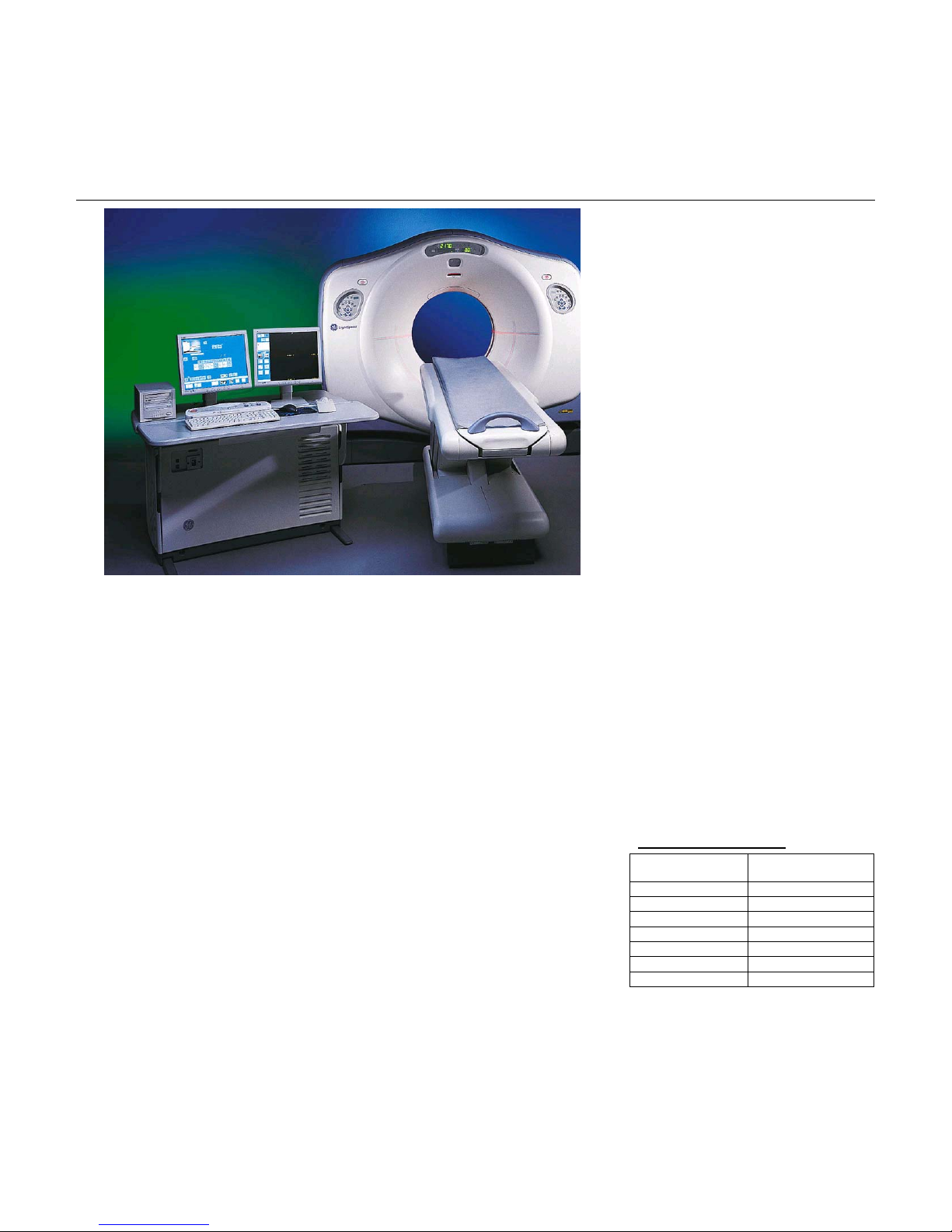
LightSpeed16
With Xtream
CT Scanner System
TM
• microVoxel
reformatted 2D resolution through the
optimum choice of sub-millimeter slice
thickness and reconstructed voxel size.
• Unmatched Volume Image Quality
specification in all planes (sagittal, coronal
and axial): 15.4 lp/cm @ 0% MTF @ 0.5
sec. Rotation
• HiLight
deliver consistent image quality with its
21,888 individual elements: 16 rows of
0.625mm thickness and 8 rows of 1.25mm
thickness
• Xtream
workflow design, breaks through existing
limits on speed, image quality and flexibility
to provide an optimized workflow solution
from acquisition to final report.
• Lowest dose acquisition using SmartmA,
an automatic modulation technique and DLP
display that tells the operator the dose
before the scan starts.
• HyperPlane
tackles the inherent issues with fast, high
pitch helical scanning by reducing helical
artifacts and dose, and optimizing the slice
profile.
• CrossBeam
solves the technical challenge of cone beam
artifacts.
• Large breadth of Advanced Software
Applications: Advanced Lung Analysis, CT
Colonography, Advanced Vessel Analysis,
Brain and Body Perfusion, Cardiac Analysis,
imaging improves 3D and
TM
Matrix II Detector is designed to
TM
technology, a revolutionary new
TM
reconstruction algorithm
TM
reconstruction algorithm
GE Medical Systems-America
Milwaukee, USA - Fax: 1 414 544 3384
GE Medical Systems-Asia:
Tokyo, Japan - Fax: 81 425 85 5490
Hong Kong - Fax: 852 2559 3588
GE Medical Systems-Europe
Cardiac Function, SmartScore Pro and
Advantage Sim.
• Compact system design of the
LightSpeed
28m² (302 square feet).
• Productivity features designed for the CT
Technologist: In-Room Start, Remote
Gantry Tilt, Breathing Lights with countdown
timer, Gantry Controls mounted on all four
corners of the gantry and an Integrated IV
Pole at the foot of the table.
• 1700 mm scannable range for full body
scans.
• 254 GB Disk (system, image, scan disks)
stores up to 250,000 512
scan data files.
• Cardiac acquisition with Segment, Burst
and Burst Plus enable you to scan patients
with heart rates from 40 to 110 BPM, and
provide for temporal resolution up to 65
ms.
• Color Coding for Kids, winner of a
National Heroes Award from the Emergency
Medical Services for Children, provides
pediatric scan protocols based on the
Broselow-Luten
Color Coding system is incorporated into the
protocol selection on the operator’s console
and is designed to facilitate pediatric
emergency care and reduce medical errors.
• VariViewer
review mode that can change the slice
thickness reconstruction instantaneously,
resulting in the ability to “scan thin and view
thick.”
16
allows for installation in only
2
images and 2881
TM
Pediatric System. This
TM
: provides an interactive axial
Clinical Performance
Chest / Abdomen / Pelvis
TM
Coverage 600 mm
Rotation 0.5 sec.
Mode 16 x 0.625 mm
Pitch 1.75:1
mA 420
mAs 210
Speed 35 mm/s
Scan Time 17.1 seconds
* Option
Page 2

g
Product Data Sheet – rev 4.2
July 4th 2003
Page 2
Peripheral Run-Off
Coverage 1,400 mm
Rotation 0.5 sec.
Mode 16 x 1.25 mm
Pitch 1.75:1
mA 380
mAs 190
Speed 70 mm/s
Scan Time 20 seconds
High Resolution Chest
Coverage 200 mm
Rotation 0.5 sec.
Mode 16 x 0.625 mm
Pitch 1.75:1
mA 440
mAs 220
Speed 35 mm/s
Scan Time 5.7 seconds
The net result is that in many cases, helical
scans on the Lightspeed
faster than 4-slice CT systems. With the
Lightspeed
second scan speed and 0.5625:1, 0.9375:1,
1.375:1, and 1.75:1 helical pitches. This
added performance, at the same image
quality, may allow you to: reduce contrast
media, perform better thin-slice CT
angiography exams, use thinner slices for
most exams, and perform longer helical exams
without tube cooling delays.
The LightSpeed
performance through a balanced design
that focuses on image quality, coverage,
and exam speed.
16
Main Features
• Full 360° rotation speed of 0.5 sec. provides
for improved temporal resolution and image
quality in areas such as cardiac imaging;
• Faster scan times enable shorter breath
holds and more comfortable exams for
patients;
• Faster scan times reduce the occurrence of
re-scans by lowering the possibility of
patient motion during the exam;
• Routine scanning with a slice thickness of
0.625mm - optimizes lesion detection and
facilitates the use of thinner images for
volume presentations.
• Reduced partial volume artifacts:
16
are up to 12 times
, users can routinely use a 0.5
16
delivers this level of
LightSpeed16
With Xtream
CT Scanner System
• Prospective or retrospective image
reconstruction of 0.625 mm, 1.25 mm,
2.5 mm, 3.75 mm, 5 mm, 7.5 mm or 10
mm images from inherently thinner
acquisition data sets;
• For both helical and axial acquisitions.
• Image decomposition to:
• Retrospective reconstruction of thin
images from data sets where thicker
images were initially reconstructed;
• Facilitates more detailed image analysis
without need for re-scans;
• Improves 3D visualization;
• For both helical and axial acquisitions
• Up to 2,881 multi-slice 1-sec scan rotations
stored on disk. Facilitates retrospective
image decomposition during off hours.
• Eight fundamental scan modes to simplify
the inherently complex nature of multi-slice
helical scanning.
• Standard set of clinically- proven
protocols derived from leading luminary
sites around the world. Up to 8,460
protocols can be edited, modified and stored
on the system.
• Remote Gantry Tilt from the Operator’s
Console to increase exam speed, including
built-in safety features to prevent accidental
contact of the gantry with the patient.
• Built-in patient breathing lights and digital
counter provides a goal-oriented approach
to coach the patients in holding their breath
during an exam.
• SmartStart gantry-mounted start scan
button and countdown display, facilitates
single-technologist operation by allowing
start of scan at the gantry, with a visual
reminder of time until X-ray initiation.
• SmartHelical GE proprietary, non-linear
interpolation algorithms, balance slice
profile, helical pitch, image noise and
required technique.
• SmartTrack advanced hardware and
software for X-ray beam tracking minimizes
patient dose.
• SmartTools software automates every
exam task in order to increase throughput.
• SmartBeam
optimizes X-ray beam filtration
independently for body and head
applications.
• HiRes Chest software provides a singleslice, high-resolution scan mode that
minimizes dose for this critical application.
TM
hardware and software
GE Medical Systems-America
Milwaukee, USA - Fax: 1 414 544 3384
GE Medical Systems-Asia:
Tokyo, Japan - Fax: 81 425 85 5490
Hong Kong - Fax: 852 2559 3588
GE Medical Systems-Europe
16
• SmartPrep, standard on LightSpeed
provides software for real-time monitoring of
contrast enhancement.
• * Direct3D, makes 3D routine and instant
by building the 3D model during axial image
reconstruction, reducing the need for user
interaction.
• * SmartScorePro, provides EKG-gated
hardware and software on the Advantage
Workstation for coronary artery calcium
scoring.
• * CardiacSnapShot, provides software
and hardware to perform EKG-gated
reconstructions of the heart in SnapShot
Segment mode.
- SnapShot Segment is a single sector
protocol using information from one heart
cycle to generate an image with temporal
resolution of 250ms.
- SnapShot Burst is a multi-sector protocol
using up to two sectors from two different
heart cycles to produce an image with
temporal resolution of 125ms.
- SnapShot Burst Plus is a multi-sector
protocol using up to four sectors of data
from four different heart cycles to produce
images with temporal resolution to 65ms.
, DLP (Dose Length Product), and
• CTDI
w
Dose Efficiency display during scan
prescription provides patient dose
informatbon to the operator.
,
Interactive CT Technology
The LightSpeed
exceptional computer and image processing
power that significantly enhances clinical
productivity, building upon the strength of the
LightSpeed family - true interactive CT
technology.
Interactive CT embodies a variety of design
choices all striving to enhance operator and
department productivity. A truly interactive CT
system will:
• Provide a user interface beyond “intuitive”
to become purely “natural” - from the
screens to the console hardware itself;
• Allow two users to review cases side-by-
side, with minimal interference;
• Supply a truly multi-tasking environment
where even advanced image processing
can take place quickly and simultaneously
with other processes underway;
• Operate with a very high degree of
automation, yet allow patient-specific
16
CT Scanner supplies
* Option
Page 3

g
Product Data Sheet – rev 4.2
July 4th 2003
Page 3
changes to be easily made, with virtually no
restrictions;
• Be as self-teaching as possible, and have
on-line access to tutorials as needed.
One key element of this design is to combine
some of the best features from several
product families into one state-of-the art CT
system. For example, the LightSpeed
Scanner combines:
• SmartTools productivity software to
automate every step of the examination,
critical for ensuring the highest productivity
and throughput possible with the
LightSpeed
• Large screen interface for controlling scan
acquisition easily, with virtually everything at
a single glance;
• Excellent simultaneity and multi-tasking
performance;
• Completely protocol-driven scan control
with a dramatic reduction in number of
screens;
• Highly flexible editing tools that allow easy
tailoring of the exam to the patient;
• Large, 1024 color display;
• Leading edge, real-time image processing
(MPR, MPVR, Volume Viewer*).
In summary, primary benefits of Interactive
CT on the LightSpeed
• A natural scan control user interface
• Dramatic reduction in the number of
• Easier and more flexible protocols
• Much more flexible and intuitive graphic
• View/Edit Wizard™ intuitively adjusts
• DynaPlan Plus™ full screen display
• Large color screen
• Extensive use of picture icons and color
• Large on-screen controls and attractive
16
CT Scanner;
16
Scanner:
screens; only 2 screens to set up first
scan and 1 screen for real-time
monitoring while scanning;
prescription process with a 1024
Localizer;
dependent parameters automatically in
response to operator-initiated changes
and highlights them for quick review; also
alerts the operator to incompatible
dependencies requiring operator
intervention;
illustrates scan status pictorially, with
real-time feedback.
cues enhance ease of use;
color palette provide comfortable viewing
over extended periods.
16
CT
LightSpeed16
With Xtream
CT Scanner System
• Enhanced multi-tasking allows operators to
review more than one exam simultaneously,
independently - even with AutoView and
AutoFilm on/
• BrightBox™ dedicated controls for
image next, prior, manual paging and
trackball W/L helps make two person
image review practical;
• Up to four 512x512 images from four
different exams can be viewed on a large
1024 color display.
• SmartmA™ User Interface - automatically
optimizes mA to maintain constant image
noise when collimation/detector
configuration, scan mode, scan rotation
speed, table speed, or image thickness
changes. It takes the guesswork out of
setting scan technique when changing
parameters (note: user must select initial
Noise Index as well as maximum mA
setting). Noise index enable 100% Image
Quality reproducibity from one patient to
another and from one user to another.
• Protocol Pro™ protocol manager - provides
operator control of automated features (like
AutoFilm, AutoStore, and AutoTransfer) on
per patient basis.
• Patient demographics and exam protocols
can be preprogrammed in advance of
patient arrival through the Schedule Patient
feature.
• A preprogrammed selection of AutoView
and Image Review Layouts allow simple
customization of the image presentation to
match the anatomical area of interest without the complexity of free-form
“windows”.
• ImageWorks™ provides instant access to
advanced image processing features such
as MIP, MPR, MPVR, Volume Viewer*,
Advanced Vessel Analysis*, CT Perfusion
2* and DentaScan*.
• No waiting for network transfer or image
retrieval from archive media.
• Background filming allows use of the full
screen for AutoView and image
review/processing without interruption when
auto or batch filming. Special “one touch”
controls provide on-screen viewing of
camera progress during AutoFilm without
disrupting other image processes in
progress.
• ProView™ visualization algorithms
available to enhance anatomical structures
without additional image reconstruction
time.
GE Medical Systems-America
Milwaukee, USA - Fax: 1 414 544 3384
GE Medical Systems-Asia:
Tokyo, Japan - Fax: 81 425 85 5490
Hong Kong - Fax: 852 2559 3588
GE Medical Systems-Europe
• Operator console convenient to locate in
suite.
• Computer, image processor and image
reconstruction hardware completely
integrated in base of console - no
separate computer cabinet to site;
• Split table top allows unrestricted patient
viewing while still supporting 2 large color
monitors;
• Front and back work surfaces can be set
during installation within a range of
vertical heights that help accommodate a
variety of siting requirements - especially
surrounding the height of the console
relative to the window into the scanning
suite.
• Work surface accommodates a large variety
of working conditions and individual
operator preferences.
• Wide work surface has room for papers,
patient charts, logbooks or other
peripheral devices;
• Wide area also helps make two person
operation more comfortable and
practical;
• All console components (monitors,
keyboard, mouse and BrightBox) are
free-standing and can be easily moved
on the front work surface;
• All surfaces made of high-impact resin
that hides marks and are easy to clean.
• Direct network connection means a multi-
suite Ethernet card is not required for a
gateway out of the suite - saving costs and
simplifying installation.
• Learning Solutions provides an on-line
Operator manual detailing system operation
via a multi-media CD-ROM player integrated
into the front of the operator console.
Learning Solutions can also be accessed on
a stand alone PC providing flexibility and
productivity for on demand learning of
system operation
Advanced Tube & Generator
Technology
• The Performix X-ray tube, with 6.3 MHU of
storage and 53.2 kW operation, provides
increased helical performance with greater
patient throughput and virtually no tube
cooling. Advanced technology in the
Performix tube includes a metal-ceramic
frame for long life, a high-speed bearing for
sub-second scanning, a high-efficiency
motor to accelerate the large anode and
* Option
Page 4

g
Product Data Sheet – rev 4.2
July 4th 2003
Page 4
efficient cooling for high throughput and
superior helical performance.
• Wide range of technique factors (10 to 440
mA, in 5 mA increments) gives the operator
and physician flexibility to tailor technique to
specific needs, optimizing patient dose, and
providing the power needed to perform a
broad spectrum of axial and helical
examinations.
System Specifications
Scan Modes:
16
The LightSpeed
virtually any clinical application due to its wide
variety of scan modes. With the LightSpeed
body CT studies are easier to perform and
more productive than ever before.
Helical:
• Continuous 360° scanning with table
incrementation and no interscan delay.
• Scans can be acquired in a wide variety of
speeds.
Axial:
• Up to 16 contiguous axial slices acquired
simultaneously with each 360° rotation, with
the time between scans set by the userselected interscan delay (ISD) or intergroup
delay (IGD).
• Scans may be easily clustered in groups to
allow multiple scans in a single breath hold.
• Minimum scan-to-scan cycle time of only 1.5
sec with table moves of ≤ 10 mm (any scan
time).
Scout™:
• Single radiographic plane for scan
• Extended range matches helical scannable
localization and graphical prescription of
prospective reconstruction;
range.
Helical Scans
Slip ring technology has advanced axial
scanning by enabling scans with zero
interscan delay and simultaneous table
movement.
CT system can perform
16
GE Medical Systems-America
Milwaukee, USA - Fax: 1 414 544 3384
GE Medical Systems-Asia:
Tokyo, Japan - Fax: 81 425 85 5490
LightSpeed16
With Xtream
Hong Kong - Fax: 852 2559 3588
GE Medical Systems-Europe
CT Scanner System
Helical Multi-slice Modes: Prospective Multiple-
Simplified scan prescriptions and easy-to-use
default protocols make the LightSpeed
and efficient in patient set up.
Multi-slice acquisitions and short intergroup
delays significantly reduce potential misregistration between scans by increasing the
number of scans possible in a patient breath
hold. Contrast agents may be better utilized
as well due to significantly faster scan
acquisition.
Helical protocols are almost identical to
“classical” axial scan protocols. At the
beginning of a study, the operator selects the
,
type of exam with the anatomical programmer,
and indicates the desired scan range - either
manually, or from a Scout.
After completing the prescribed exam, the
system remains ready to continue with
additional helical scans or a set of axial scans.
The operator may reconstruct helical scans
prospectively with up to 90% overlap, and
retrospectively, at any arbitrary table location
in 0.1 mm increments.
Helical Multi-slice Modes
The complex nature of helical multi-slice
scanning has been simplified by grouping
all critical acquisition parameters within 8
basic scan modes, all optimized for image
quality and speed. For eight-slice
acquisition: 0.625: 1; 0.875: 1; 1.35: 1 and
1.675: 1. For sixteenslice acquisition:
0.5625: 1; 0.9375: 1; 1.375: 1 and 1.75: 1.
These clinically derived multi-slice scan
modes offer a wide range of selections
that carefully balance acquisition speed,
image thickness, artifact level and
retrospective image reconstruction
flexibility.
This simplified user interface guides the
user in the choice of scan parameters.
The user selects a pitch mode, a desired
image slice thickness and table travel per
rotation. The user interface also displays
the resulting choice of retrospective image
thicknesses available for each choice of
acquisition parameters.
The 16 slice helical acquisition modes
provide table speeds from 5.625
mm/rotation up to 35 mm per rotation,
enabling scan speeds that are up to 12
times faster than 4-slice helical scanners.
16
fast
Thickness Reconstruction:
For all helical scan modes, the operator can
choose to reconstruct images prospectively in
any of the defined nominal slice thicknesses.
In addition to the initial reconstructed slice
thickness, the operator has the option to
prospectively specify additional images to be
reconstructed from a single raw data set.
These images can be reconstructed at any of
the defined nominal slice thicknesses
available for a given table speed and scan
mode.
This effectively facilitates later, more detailed
image analysis without additional patient
scans and subsequent dose and image
registration concerns.
8-SLICE HELICAL MODES
Table Speed (mm/rotation)
Slice
Thick
-ness
(mm)
1.25 6.25 8.75 13.5 16.75
3.75 6.25
Pitch
0.625:1
2.5 6.25
12.5
12.5
5 6.25
12.5
7.5 6.25
12.5
10 6.25
12.5
0.875:1
8.75
17.5
8.75
17.5
8.75
17.5
8.75
17.5
8.75
17.5
1.35:1
13.5
27.0
13.5
27.0
13.5
27.0
13.5
27.0
13.5
27.0
1.675:1
16.75
33.5
16.75
33.5
16.75
33.5
16.75
33.5
16.75
33.5
* Option
Page 5

g
Product Data Sheet – rev 4.2
July 4th 2003
Page 5
16-SLICE HELICAL MODES
Table Speed (mm/rotation)
Slice
Thick-
ness
(mm)
0.625 5.625 9.375 13.75 17.5
1.25 5.625
3.75 5.625
Helical Scan Parameters
Scan Speeds: Full 360° rotational scans in
0.5, 0.6, 0.7, 0.8, 0.9, 1.0 seconds.
Scan Technique
— kVp: 80, 100, 120, 140
— mA: 10 to 440 in 5 mA increments
— Power: 0.8 to 53.2 kW
— Focal Spot Selection:
Small spot for up to 24 kW
Large spot for greater than 24 kW
Single Acquisition
maximum.
Helical Tilt
with the gantry tilted to a maximum of 30
degree, in half degree increments.
Multiple Acquisition Maximum
Multiple scans may be acquired in one
series to produce up to 3,000 contiguous
helical images. Up to 2,881 seconds
helical coverage is possible in multiple
series.
Minimum Inter-Group Delay
seconds between adjacent helical scans
Pitch
0.5625
:1
11.25
2.5 5.625
11.25
11.25
5 5.625
11.25
7.5 11.25 18.75 27.5 35
10 11.25 18.75 27.5 35
: helical acquisition is possible
0.9375
9.375
18.75
9.375
18.75
9.375
18.75
9.375
18.75
:
: 120 second scan
1.375
:1
13.75
27.5
13.75
27.5
13.75
27.5
13.75
27.5
Scan Time:
(IGD): 5
:1
1. 75:1
17.5
35
17.5
35
17.5
35
17.5
35
LightSpeed16
With Xtream
CT Scanner System
Scan Fields of View
— 25 cm for adult head
— 25, 50 cm for body
— 25 cm for pediatric head
Helical Scan Enhancements
Full simultaneity allows complete image
display, processing and analysis, as well
as image archival and filming, concurrent
with scanning and reconstruction -- even
when acquiring helical images in a multislice mode.
Confirm Rx to X-Rays on: < 15 sec. for
any state of tube and gantry; < 10 sec.
with the gantry rotating
Anatomical Programmer: a ten-region
anatomical selector allows quick and easy
access to 90 user-programmable
protocols per region. Separate selector
for adult and pediatric exams. There are
four selection tabs to select: GE, User,
Service and Most Recent Patient.
Copy/Paste is supported for easy
modification and copying of protocols.
Ten user-defined regions. Each region
has one default protocol displayed with the
anatomical selector for very fast access to
most commonly used protocols
Protocols include preset scan time, kVp,
mA, scan mode, slice thickness and
spacing, table speed, scan FOV, display
FOV and center, recon algorithm and
special image acquisition and processing
options
Any scan parameters may be edited for
each scan or all scans - either before or
during an exam. The number of scans
may also be easily changed.
AutoScan™: Fully automates longitudinal
table movement and start of each scan.
AutoVoice™: 3 preset (English) and 17
user-defined messages automatically
deliver patient breathing instructions;
especially useful for multiple helical
scanning.
Trauma Patient: Allows patient scans and
image display/analysis without entering
patient data before scanning.
:
GE Medical Systems-America
Milwaukee, USA - Fax: 1 414 544 3384
GE Medical Systems-Asia:
Tokyo, Japan - Fax: 81 425 85 5490
Hong Kong - Fax: 852 2559 3588
GE Medical Systems-Europe
Biopsy: Simplified prescription for single
or multiple scans around an arbitrary table
position aids biopsy studies.
Advanced Artifact Reduction (AAR)
Filter significantly reduces streaking
artifacts when highly absorbent objects
are in the field of view – ie: large
shoulders, screws.
Helical Image Reconstruction
Reconstruction Algorithms: Soft Tissue,
Standard, Detail, Bone, Bone Plus, Lung
and Edge
Reconstruction Matrix
Display Matrix
Display FOV
center, prospective/retrospective target
selection.
CT Number Scale
Helical Reconstruction Times:
Reconstruction time as fast 6
Typical 0.167 sec. image-to-image
Maximum image-to-image cycle
Iterative bone processing
Minimum DFOV:
Minimum Pixel Size:
Queued Recon
processed continuously and
simultaneously with other processes on
the system including scanning.
Prospective recon will be prioritized over
retrospective recon.
Priority Recon Queuing
selection marks most recent rotation for
: Freely variable center/off-
images per second
recon in normal 16 slice recon mode.
time is ± 10% for prospective and
retrospective image-to-image display.
This applies for 512 matrix; any
display FOV; in AutoView (all
layouts); with concurrent filming and
image archival for all scan modes.
increases time by 250 milliseconds.
Iterative bone processing, which is
always enabled for adult head
scanning, reduces image artifacts in
head scans stemming from X-ray
beam hardening effects.
: 512
: 1024.
: -1024 to 3071 HU
9.6 cm
0.19 mm
: Requests will be
: One touch
* Option
Page 6

g
Product Data Sheet – rev 4.2
July 4th 2003
Page 6
next available recon. Available during or
after scanning.
Images annotated to indicate continuous
scan acquisition with table incrementation:
HE (helical) + Pitch
Table speed
Prospective Multiple Reconstruction
(PMR): Up to 3 sets of reconstructions can
be pre-programmed as part of the scan
protocol prior to acquisition. The operator
can select different start/end location, slice
thickness, interval, reconstruction
algorithms and display fields of view for
each reconstruction. This frees the
operator from sitting at the console and
directly contributes to increased
productivity.
Prospective Recon: Operator may initiate
full recons at any table location in
increments of 1/10 the image thickness;
image thickness remains constant.
Retrospective Recon: Operator may
initiate full recons at any table location in
0.1 mm increments; image thickness
remains constant.
Retrospective Image Decomposition:
The operator has the option to
retrospectively decompose the original
raw data set and reconstruct additional
images at any of the defined nominal
image thickness available for a given table
speed and scan mode.
LightSpeed16
With Xtream
CT Scanner System
Helical Scan Protocols
All protocols assume 120 kVp scans under
typical clinical conditions.
Single Helical Scans:
Scan
Time
10 sec. 440
20 390-440
30 330-380
40 290-350
50 260-320
60 230-310
70 210-300
80 180-280
90 170-270
100 160-260
110 150-250
120 140-230
Multiple Helical Scans
(contiguous helical coverage with 5second IGD):
Scan
Time IGD
10 sec. 5 sec. 3 340-420
20 sec. 5 sec. 2 300-360
30 sec. 5 sec. 2 230-310
40 sec. 5 sec. 2 190-290
50 sec. 5 sec. 2 170-270
60 sec. 5 sec. 2 140-240
Contiguous Helical Coverage
Multiple helical scans can be performed in
succession with only 5-second delays
between helical scans, providing up to
2,881 contiguous rotations (with up to
1,500 images in one series).
(The following chart assumes 120-second
helical with 5-sec IGD)
Maximum
mA
No.
Scans
4 300-400
5 270-390
6 240-360
3 240-330
4 180-310
3 180-280
4 140-240
3 140-230
4 110-190
3 120-200
4 90-160
3 100-170
Max
mA
GE Medical Systems-America
Milwaukee, USA - Fax: 1 414 544 3384
GE Medical Systems-Asia:
Tokyo, Japan - Fax: 81 425 85 5490
Hong Kong - Fax: 852 2559 3588
GE Medical Systems-Europe
Total Scan Total Elapsed Max
Time (sec.) Time (sec.) mA
150 155 100-200
200 205 80-150
450 465 50-70
Helical Scan Image Quality
Volumetric Helical Scan Image Quality
16
With LightSpeed
isotropic CT scanner, it is now possible to
specify coronal and sagittal image quality:
1. Visual Measurement:
Reformatted resolution is demonstrated on
the Nuclear Associates AAPM High
Contrast Resolution Insert #76-413.
0.5mm
0.4mm
An Effective 0.5 mm voxel size is clearly
seen in coronal and sagittal views.
2. Statistic Measurement:
Volumetric MTF is computed from the X,Y
and Z axis of a 0.2mm bead using sagittal
and coronal images of the 8” Catphan,
MTF module with bead source #CTP445.
Detail Algorithm
MTF (z-axis) is 12.4 lp/cm @ 10%, 15
lp/cm @ 0% which is a 0.333 mm limiting
resolution
In Plane Helical Scan Image Quality
For details of scan technique please refer
to the technical reference manual.
High-Contrast Spatial Resolution
On GE Performance phantom:
Standard Algorithm
being a sub-millimeter
* Option
Page 7

g
Product Data Sheet – rev 4.2
July 4th 2003
Page 7
• 0.584 mm limiting resolution
• 4.0 lp/cm @ 50% MTF
• 6.5 lp/cm @ 10% MTF
• 8.5 lp/cm @ 0% MTF
Hi-Res Algorithm (Edge).
• 0.324 mm limiting resolution
• 8.5 lp/cm @ 50% MTF
• 13.0 lp/cm @ 10% MTF
• 15.4 lp/cm @ 0% MTF
Line pair values decrease with larger focal
spot (by 5% with Standard and by 7% with
Hi-Res); limiting resolution is unaffected.
Low-Contrast Detectability
On 8 inch (20 cm) CATPHAN phantom:
5 mm @ .3% at 13.3 mGy
3 mm @ .3% at 37.2 mGy
Noise:
On either an AAPM water phantom or GE
Quality Assurance phantom:
0.32% +/- 0.03% at 28.5 mGy (2.85 Rad)
CTDI:
On CTDI Head and Body Dose Reference
Phantoms:
expressed in mGy/100 mAs for
CTDI
vol
IEC pitch 1: (normalized to a pitch of 1).
Head 20.9 mGy/100 mAs
Body 10.6 mGy/100 mAs
LightSpeed16
With Xtream
CT Scanner System
Axial Scans
Multi-slice acquisitions and short interscan
delays significantly reduce potential missed
registration between scans by increasing the
number of scans possible in a patient breath
hold. Contrast agents may be better utilized
as well due to significantly faster scans.
Axial Multi-slice Prescription
Simplified scan prescriptions and easy-to-use
default protocols make the Lightspeed
Scanner fast and efficient in patient set-up.
Axial protocols are nearly identical to helical
scan protocols.
Axial Multi-slice Modes
The LightSpeed
sets of 8 or 16 contiguous images in one 360°
rotation.
For each rotation of the gantry, the
LightSpeed
data. There are five reconstruction modes
available for creating images from the
multi-slice scan data (1i, 2i, 4i, 8i, and 16i).
By using 1i, 2i, 4i, and 8i reconstruction
modes, scan data can be combined prior
to image reconstruction to create slices
with reduced partial-volume artifacts. This
is particularly useful for posterior-fossa
imaging.
1i Mode:
• Produces 1 image per rotation
• Nominal Thickness: 1.25, 5, 10 mm
2i Mode:
• Produces 2 images per rotation
• Nominal Thickness: 0.625, 2.5, 5, 7.5, 10
mm
4i Mode:
• Produces 4 images per rotation
• Nominal Thickness: 2.5, 3.75, 5 mm
8i Mode:
• Produces 8 images per rotation
• Nominal Thickness: 1.25, 2.5 mm
16i Mode:
• Produces 16 images per rotation
16
acquires axial scans in
16
collects 16 rows of scan
16
CT
GE Medical Systems-America
Milwaukee, USA - Fax: 1 414 544 3384
GE Medical Systems-Asia:
Tokyo, Japan - Fax: 81 425 85 5490
Hong Kong - Fax: 852 2559 3588
GE Medical Systems-Europe
• Nominal Thickness: 0.625, 1.25 mm
Axial Scan Parameters
Scan Time:
• 0.5, 0.6, 0.7, 0.8, 0.9, 1.0, 2.0, 3.0 and 4.0
second full scans (360° acquisition)
Scan Technique:
• kVp: 80, 100, 120, 140
• mA: 10 to 440, in 5 mA increments
• Power: 0.8 to 53.2 kW
• Focal Spot Selection:
• Small spot for up to 24 kW
• Large spot for greater than 24 kW
Scan Plane Geometry:
• +/- 30° gantry tilt, in 0.5° increments
• Longitudinal positioning in 0.01 mm per slice
increment. Gantry display in 0.5 mm
increments.
Interscan Delay (ISD):
• Minimum ISD with table movements of
0 - 10 mm: 1.0 sec.
• Minimum ISD with table movements of more
than 10 mm and up to 20 mm: 1.3 sec
• User-selectable.
Inter Group Delay (IGD):
• Minimum IGD is the same as minimum ISD;
also user-selectable.
Scan-to-Scan Cycle:
• Minimum scan-to-scan cycle of 1.5 seconds
possible for 0.5 sec. scan speed with
minimum ISD's.
Scan Fields of View:
• 25 cm for adult head
• 25, 50 cm for body
• 25 cm for pediatric head
Scan with no table incrementation,
contiguous image location, or skipped
image location are possible. Overlapped
axial scans are not possible.
Axial Image Reconstruction
Reconstruction Algorithms: Soft Tissue,
Standard, Detail, Bone, Bone Plus, Lung and
Edge.
* Option
Page 8

g
Product Data Sheet – rev 4.2
July 4th 2003
Page 8
Reconstruction Matrix: 512
Display Matrix: 1024.
Display FOV: Freely variable center/off-center,
prospective/retrospective target selection.
CT Number Scale: -1024 to 3071 HU
Axial Image Reconstruction:
• Reconstruction time as fast as 6 images
per second.
• Typical 0.167 sec. image-to-image recon in
16 slice recon mode.
• Maximum image-to-image cycle time is
± 10% for prospective and retrospective
image-to-image display. This applies for
512 matrix; any display FOV; in
AutoView (all layouts); with concurrent
filming and image archival for all scan
modes.
• Iterative bone processing increases time by
250 milliseconds.
Prospective Multiple Reconstruction
(PMR): Up to 3 sets of reconstructions can
be pre-programmed as part of the scan
protocol prior to acquisition. The operator
can select different reconstruction
algorithms and display fields of view for
each reconstruction. This frees the
operator from sitting at the console and
directly contributes to increased
productivity.
The operator has the option to reconstruct
the original raw data set at any of the
defined nominal slice thicknesses.
Reconstructions can be prescribed down
to 1/16 the original acquisition image
thickness for images acquired in the 1i
scan mode, down to 1/8 the original
thickness for 2i mode, and down to 1/4 the
original thickness for 4i mode.
Similarly, additional reconstruction
supports partial-volume artifact reduction
by reconstructing images with 4, 8, or 16
times the acquisition image thickness.
These reconstruction features effectively
facilitate later, more detailed image
analysis without additional patient scans
and subsequent dose and image
registration concerns.
The following table illustrates the
retrospective reconstruction image
thicknesses available for each acquisition
thickness and mode:
LightSpeed16
With Xtream
CT Scanner System
Prospective Perscri pti on
Scan Mode
16 row 0.625
16row 1. 25
8 row 1. 25
8row 2. 5
Axial Scan Protocols
All protocols assume 120 kVp scans under
typical clinical conditions.
Standard Scans:
Scan
Time ISD mA Scans
1 sec. 1 sec. 440 18-45 0:35-1:27
1 1 400 24-55 0:47-1:49
1 1 360 32-68 1:03-2:15
1 1 340 37-76 1:13-2:31
1 1 320 43-86 1:25-2:49
1 1 300 50-97 1:37-3:11
1 1 280 58-110 1:45-3:37
1 1 260 66-122 1:55-3:59
1 1 240 74-135 2:07-4:21
1 1 220 84-152 2:21-4:49
1 1 200 94-168 2:37-5:21
2 1 200 37-77 1:13-2:33
2 1 180 42-86 1:23-2:51
• Cluster Scans (All cluster protocols assume
9-second clusters of five slices, 1-second
scans with 1-second interscan delays and 7
seconds between clusters).
Sl i c e
Thi ckness
Rec on
Slice Thicknesses
16i - 0.625mm
8i - 1.25mm
4i - 2. 5mm
2i - 5. 0mm
16i - 1.25mm
8i - 2. 5mm
4i - 5. 0mm
2i - 10mm
8i - 1.25mm
4i - 2. 5mm
2i - 5. 0mm
1i - 10mm
8i - 2. 5mm
4i - 5. 0mm
2i - 10mm
Acquisition
Time
GE Medical Systems-America
Milwaukee, USA - Fax: 1 414 544 3384
GE Medical Systems-Asia:
Tokyo, Japan - Fax: 81 425 85 5490
Hong Kong - Fax: 852 2559 3588
GE Medical Systems-Europe
mA
440 15-45 (3-11) 0:41-2:49
400 25-55 (5-13) 1:13-3:21
340 35-75 (7-18) 1:45-4:41
320 45-85 (9-20) 2:17-5:13
300 50-95 (10-22) 2:33-5:45
280 60-110 (12-25) 3:05-6:33
260 75-125 (13-28) 3:21-7:21
240 85-145 (14-31) 3:37-8:09
220 100-170 (16-34) 4:09-8:57
200 115-185 (18-38) 4:41-10:01
180 135-250 (22-43) 5:45-11:21
# Scans
(Clusters)
Acquisition
Time
Axial Scan Image Quality
For details of scan technique parameters,
please refer to the technical reference
manual.
High Contrast Spatial Resolution:
On GE Performance phantom:
Standard Algorithm
• 0.584 mm limiting resolution
• 4.0 lp/cm @ 50% MTF
• 6.5 lp/cm @ 10% MTF
• 8.5 lp/cm @ 0% MTF
Hi-Res Algorithm
• 0.324 mm limiting resolution
• 8.5 lp/cm @ 50% MTF
• 13.0 lp/cm @ 10% MTF
• 15.4 lp/cm @ 0% MTF
Line pair values decrease with larger focal
spot (by 5% with Standard and by 7% with
Hi-Res); limiting resolution is unaffected.
Low-Contrast Detectability
On 8 inch (20 cm) CATPHAN phantom:
5mm @ .3% at 13.3 mGy
3mm @ .3% at 37.2 mGy
* Option
Page 9

g
Product Data Sheet – rev 4.2
July 4th 2003
Page 9
Noise:
On either an AAPM water phantom or GE
Quality Assurance phantom:
0.32% +/- 0.03% at 29.3 mGy (2.93 Rad)
CTDI:
On CTDI Head and Body Dose Reference
Phantoms:
CTDI expressed in mGy/100 mAs:
Head 16.8 mGy/100 mAs center
17.0 mGy/100 mAs surface
Body 5.50 mGy/100 mAs center
10.0 mGy/100 mAs surface
CTDI
expressed in mGy/100 mAs:
100
Head 18.7 mGy/100 mAs center
17.9 mGy/100 mAs surface
Body 5.4 mGy/100 mAs center
11.2 mGy/100 mAs surface
CTDI
expressed in mGy/100 mAs:
vol
Head 18.4 mGy/100 mAs
Body 9.3 mGy/100 mAs
Scout Scans
ScoutView™ scans provide excellent
detail for anatomical localization in
conjunction with scan prescription.
Scan locations may be prescribed at the
operator console either graphically (via
mouse), or explicitly (keyboard entry) from
a Scout scan.
Prescription of scans with multiple gantry
angles are also available on a single
Scout.
Scout Scan Parameters
Aperture: 1.25 mm effective aperture
Table speed: 100 mm/sec.
Scan Technique:
• kVp: 80, 100, 120, 140
• mA: 10 to 440 in 5 mA increments
• Power: 0.8 to 53.2 kW
LightSpeed16
With Xtream
CT Scanner System
Orientation: AP, RLAT, PA, LLAT (preset);
or any angle from 0° - 359° (manually
selected).
Axial scan prescription lines indicate scan
location to nearest 1 mm table position.
Scouts longer than 1,000 mm are auto
minified to fit the display.
User Interface
The Lightspeed16 Operator Console utilizes a
computer workstation with the following user
interface features:
• Two 20-inch monitors
• Scan/recon monitor for scan and recon
control with no image display
• Image monitor for image display,
analysis, processing, and management
• Each monitor provides a 1280 x 1024
high resolution, flicker-free display
• Optional 18” LCD Monitors.
• Scan control keyboard assembly with
intercom speaker, microphone and volume
controls
• Three button mouse with mouse pad
• BrightBox (trackball assembly)
• Two wide work surfaces
All these devices are free-standing and can be
easily moved to accommodate a large variety
of working conditions and individual operator
preferences.
Split table top allows unrestricted patient
viewing while still supporting 2 monitors. Each
work surface can be adjusted at installation to
help accommodate a variety of siting
requirements.
Desktop Overview
The user interface utilizes the paradigm of
managed work environments for a more
intuitive clinical workflow.
Virtually all clinical operations are managed
through three “virtual desktops” or applications
managers: Exam Rx, ImageWorks and
Learning Solutions. Operators can effortlessly
move back and forth between these
environments simply by clicking on an icon.
XtreamTM technology enhances multi-tasking
architecture and maintains simultaneously all
processes so no work is lost or disrupted as
desktops are switched.
GE Medical Systems-America
Milwaukee, USA - Fax: 1 414 544 3384
GE Medical Systems-Asia:
Tokyo, Japan - Fax: 81 425 85 5490
Hong Kong - Fax: 852 2559 3588
GE Medical Systems-Europe
Exam Rx:
The Exam Rx desktop environment provides
the clinical tools necessary for comfortable,
efficient control of patient studies.
These tools include patient scheduling and
data entry, exam protocol selection, protocol
viewing and editing, scan data acquisition,
image reconstruction, image display and
routine analysis, AutoFilm or manual filming,
AutoStore and AutoTransfer.
ImageWorks:
ImageWorks is a desktop environment
designed to take advantage of the
Lightspeed
and image processor.
Standard features include archive, network
and manual film control, as well as some
advanced image processing such as multiplanar reformatting (MPR), multi-projection
volume rendering (MPVR), and MR image
display. It also has optional add-on packages
for Volume Viewer*, CT Perfusion2* and
DentaScan*.
The ImageWorks desktop also provides a
gateway for DICOM 3.0 image transactions,
either through a local area network, or via
DICOM-formatted MOD media.
Learning Solutions:
The LightSpeed
line operator manual via a multi-media CDROM player integrated into the front of the
operator’s console. Learning Solutions is also
viewable on a stand-alone PC providing
flexibility and productivity for on-demand
learning of system operation.
16
CT Scanner System computer
16
provides an on-screen, on-
Exam Rx
Patient Scheduling
Patient demographics and exam protocols can
be pre-programmed in advance of patient
arrival by selecting Schedule Patient from the
scan/recon monitor. This productivity
enhancement allows entry of all or some of a
patient’s demographic data, as well as preselection of the exam protocol.
* Option
Page 10

g
Product Data Sheet – rev 4.2
July 4th 2003
Page 10
This feature is available any time a patient
exam is not currently underway.
This feature uses the same interface as New
Patient selection for simplified, consistent
programming.
Patient information can be easily recalled to
set up an immediate exam via List/Select
Scheduled Patient on the scan/recon monitor.
Pre-programmed patient exams can also be
recalled from the New Patient screen
automatically by entering the patient ID
number.
Patient Data Entry:
Patient data can be entered as part of New
Patient set-up, or can be recalled from the list
of pre-scheduled patients.
Trauma Patient ID allows patient scans and
image display/analysis without entering patient
data before scanning.
Exam Protocol Selection:
One of the main contributions of the
LightSpeed
department productivity is its simplified exam
set-up.
• Exam parameter set-up has been greatly
simplified through the exclusive use of
protocols
• Protocols can be easily selected in one of
three convenient ways:
• Two Anatomical Programmers - one for
adults and one for pediatrics - provide quick
and easy access to 8,460 userprogrammable protocols (total). Each
programmer has ten anatomical regions with
90 protocols for each region
• Default protocols have been expanded
through Protocol Pro - a “behind the scenes”
protocol manager - that allows preselection
of automated features like AutoVoice,
AutoFilm, AutoStore and AutoTransfer on a
per-exam basis.
• Protocol Pro also provides preselection of
two different window/level settings per
image for AutoFilm and can automatically
16
CT Scanner System to
• A large, graphical Anatomical
Programmer located on the New Patient
screen
• A default list of the “top 10” most
commonly used protocols located near
the anatomical programmer
• A numerical entry
LightSpeed16
With Xtream
CT Scanner System
display the 1024 Localizer each time a new
series is requested.
• Default protocols also include preset scan
time, kVp, mA, slice thickness, scan mode,
table speed, image interval, gantry tilt, scan
field-of-view, display field-of-view and
center, recon types, and breath timing
parameters.
• Any scan parameter can be edited for each
scan or all scans either before or during an
exam. Scans can be easily added or
removed from the prescription.
• Scan/recon control uses only 2 screens to
set up first scan - New Patient and Protocol
View/Edit.
Protocol View/Edit:
• A single, full screen View/Edit table allows
fast and easy examination and modification
of exam parameters before scanning begins
• Exam parameters can be changed for just
one scan, or for all scans in a series
• When used in conjunction with the 1024
Localizer, changes made in the View/Edit
table that affect the number of scans, image
interval, starting/ending locations, tilt, or
display FOV are automatically shown on the
1024 Localizer
• Any changes made directly on the 1024
Localizer display using the mouse and the
on-screen cursor controls are also reflected
automatically in the View/Edit table
• View/Edit Wizard intuitively adjusts
dependent parameters automatically in
response to operator-initiated changes and
highlights them for quick review. It also
alerts the operator to incompatible
dependencies requiring operator
intervention.
• Tab card groupings for Timing, Recon and
Filming help organize the large number of
parameters available within each protocol.
• As many as 8,460 protocols can be stored
on the Operator Console.
Scan Data Acquisition:
• Full-screen DynaPlan Plus illustrates scan
status graphically, with real-time feedback
while the exam is underway. Scans,
programmed delays (prep, breathing, intergroup), and even AutoVoice
announcements are clearly shown before
and during scanning.
• AutoScan: Fully automates longitudinal
table movement and the start of each scan
GE Medical Systems-America
Milwaukee, USA - Fax: 1 414 544 3384
GE Medical Systems-Asia:
Tokyo, Japan - Fax: 81 425 85 5490
Hong Kong - Fax: 852 2559 3588
GE Medical Systems-Europe
• AutoVoice: Preset (English) and user-
recorded messages automatically deliver
patient breathing instructions, especially
useful for multiple or multi-pass helical
scans
• Full Simultaneity allows scan and recon to
work concurrently with image display,
processing and analysis (including
computationally intensive features such as
MPR, MPVR and 3D*/MIP) while still
running image archival, filming and
networking processes.
Dose Computation & Display
CTDI
(CTDI volume), DLP (Dose Length
vol
Product), and Dose
and display during scan prescription provides
patient dose information to the operator.
CTDI
is a dose index defined by IEC 601-2-
vol
44. This index is computed automatically by
the Lightspeed
the Exam Rx screen. CTDI
number consisting of 2/3 of the CTDI
peripheral dose plus 1/3 of the CTDI
dose that is divided by the helical or axial pitch
factor.
CTDI
is a dose index based upon CTDI
100
dose measurements over a 100 mm volume,
as defined in IEC 601-2-44.
Dose Length Product (DLP) is given in
mGy*cm and is computed and displayed for
each group prior to the scan. Additionally, an
accumulated DLP is displayed for the entire
exam, as the exam prescription progresses.
The final exam accumulated DLP provides a
convenient measure for maintaining patient or
procedure dose management statistics.
Dose Efficiency is automatically
computed and displayed on the Exam Rx
screen. The dose efficiency is a measure
of how much of the Z-axis X-ray beam is
used by the system, as defined in IEC
601-2-44.
Efficiency computation
16
CT System and reported on
is a single
vol
100
central
100
AutoView Layouts:
• Eight powerful AutoView layouts provide
exceptional flexibility in tailoring the 1,024
image display to the user or the application
at hand - without the complexity of free-form
“windows.”
• AutoView Layouts include:
• 1024 AutoView image
• 768 AutoView image (matches the image
size shown on the HiSpeed Advantage
2.X Series OC monitor)
* Option
Page 11

g
Product Data Sheet – rev 4.2
July 4th 2003
Page 11
•
512 AutoView image + 512 Localizer
Scout with cut lines automatically
showing the location of the AutoView
image on the Scout
• Two 512 AutoView images (same image
but at different window/level settings) +
512 Localizer Scout with cut lines
automatically showing the location of the
AutoView images on the Scout
• 512 AutoView image + 512 AutoFilm
image
• Last two 512 AutoView images
• Last four 512 AutoView images
• AutoLink which links the current series to
a view port
• Basic image review features such as
window/level, magnification and flip/rotate
are available for AutoView images.
• Any window not used for AutoView is
available to independent, simultaneous
review of other exams.
• Special BrightBox, a three-button trackball
device, provides independent control of
image next, prior, manual paging and
trackball window/level for any review images
in focus. This helps make two person
operation practical.
• Regardless of the AutoView Layout used,
AutoFilm viewing is available anytime via an
on-image selection - without disrupting other
image processes in progress. Background
filming allows full use of the image display
monitor for AutoView and image
review/processing without interruption
during AutoFilm.
Image Review Layouts:
• Five flexible Image Review Layouts are
provided for those applications where
greater than 512 image display may be
desired and AutoView is not required.
• Image Review Layouts include:
Note: uses short notation for screen options
• 1024 single image display
• 768 single image display
• Two 512 image display, horizontal format
• Two 512 image display, vertical format
• Four 512 image display
• Each image display window can be further
subdivided into four more images,
increasing the total number of images that
can be displayed at once to 16.
• BrightBox image control is also available for
Image Review Layouts.
LightSpeed16
With Xtream
CT Scanner System
Image Access:
• Point and click interface along with a
pictorial directory (browser) allows for easy
selection by exam, series or image
Routine Image Display:
• Image display features provided within
Exam Rx:
• Zoom/Roam
•
• Flip/Rotate
•
• Display Normal
• List/Select
• Ellipse ROI
• Measure Distance
• Grid On/Off
• Cross Reference
• User Annotation
• Exam/Series Page
• Hide Graphics
• Erase
• Screen Save
• Gray Scale Enhancement
•
ProView visualization algorithms are
available to enhance anatomical structures
without additional reconstruction time:
• Four Selections for enhancement of high
•
•
Three ways are provided to adjust window/
level of images in focus in order to meet a
variety of clinical work environments and
user preferences:
•
•
•
Explicit Magnify
ProView
contrast objects where fine detail is
required without aliasing (such as lungs)
Three Selections for modifying perceived
levels of noise and low contrast
discrimination
Six user-programmable keys on the scan
control keyboard (F6 - F11), plus one key
for returning to prior setting (F5)
On-image through middle mouse button
BrightBox trackball
Routine Measurements:
• Image measurement features provided
within Exam Rx:
• Box ROI
• Ellipse ROI
•
Trace ROI
• Measure Distance
GE Medical Systems-America
Milwaukee, USA - Fax: 1 414 544 3384
GE Medical Systems-Asia:
Tokyo, Japan - Fax: 81 425 85 5490
Hong Kong - Fax: 852 2559 3588
GE Medical Systems-Europe
• Measure Angle
• Grid On/Off
• Hide Graphics
• Erase
Screen Save
•
•
MIROI (Multiple Image ROI)
• Report Pixels
Display Preferences:
• Display settings available to tailor the overall
display (settings apply to all images in all
exams):
• Annotation Levels
• Inverse Video
• Next/Prior Each View Port
• Next/Prior Series Binding
• Continuous Report Cursor
Auto Image Management:
The Exam Rx work environment conveniently
provides for selection of AutoFilm, AutoStore
(to local or remote MOD), and AutoTransfer
(across a network).
An AutoFilm Composer provides a simple
programming interface for automated filming
set-up.
Batch Filming is accomplished through a
single keystroke which automatically prints an
entire series at a time.
Manual Image Filming:
• On-screen filming is available for any analog
or digital camera using a 3M-952 protocol.
• Images may be individually filmed manually
via “drag and drop” to the on-screen Film
Composer.
• Print Series permits automatic printing of an
entire series with one keystroke.
• Page filming permits creation of an entire
film with one keystroke.
• Multiple image formatting allows filming of
multiple images in a single film frame.
• Film formats supported are 1:1, 2:1, 4:1, 6:1,
8:1, 9:1, 12:1, 15:1, 16:1, 20:1, 24:1 and 35mm slide
Important note: The Lightspeed
comes standard with a DICOM Print Interface
configurable for multiple DICOM Print
destinations. Connections with cameras that
16
CT Scanner
* Option
Page 12

g
Product Data Sheet – rev 4.2
July 4th 2003
Page 12
do not support DICOM Print may require a
filming interface (purchased separately).
To save further filming cost, the Operator
Console can directly print to a postscript
printer such as the GE Color Printer available
as an option.
ImageWorks
ImageWorks software is designed to take
advantage of the Lightspeed
computer and image processor. This desktop
environment includes image management and
networking.
Because some of the image analysis and
display features of ImageWorks replicate
those in Exam Rx, the next section describes
only features that are incremental or
significantly different.
Image Analysis
• Multi-Projection Volume
Reconstruction
way to generate volumetric images for CT
angiography without thresholding data or
removing unwanted anatomy. An entire
volume is used to generate images in any
plane, creating real-time frames of
reference at the same time;
• Clinical utility is extended via two
additional modes:
− MIPS - enhances contrast and improves
visualization of calcifications
− Average - generates 2D radiographic
images;
•
Multi-planar Reformation (MPR):
Provides real-time assessment of anatomy
in offaxis planes. Sagittal, coronal, oblique
and curved planar reformations available;
•
Batch reformatting can also be defined
and executed for later viewing if desired;
• Image Addition and Subtraction: Includes
image addition of more than two images at
a time;
*Volume Viewer
Volume Viewer is an innovative and
powerfull suite of productivity enhanvers
(MPVR): Quick and easy
16
CT Scanner’s
LightSpeed16
With Xtream
CT Scanner System
(Volume Rendering, Volume Analysis and
Navigator) that includes :
•
Dynamic Volume Review™ for Fast
Screening
• Curved Volume Of Interest
• Protocol Management and Loading
• Review Layout Presets
• Multiple VR Objects Merge
• Pseudo Surface Shading Mode
• Predefined Cut Planes
• Volume Rendered Navigator views
• VR Preset save/recall
• 3D Rendered Lumen View
• Automatic Path Tracking
• Path Bridging (in case of occlusions)
• SmartCursor™ for Easy Navigation
• Synchronized Reformatted Views
• Cut visualization mode
*Advanced Vessel Analysis
Advanced Vessel Analysis is the ultimate
tool to assess and quantify vascular
structures, including stenosis analysis,
stent planning procedures, post stenting or
vascular surgery follow-up.
• protocol driven tools to perform quick,
flexible and accurate quantitative analysis of
vascular anatomy
• provides maximum, minimum and mean
intraluminal diameter measurements
• provides cross-sectional areas of true
orthogonal sections of the aortoiliac systems
at selected anatomical points
• clinical benefits include: stenosis sizing, pre-
and post- surgical assessment, stent
planning
• Measurements in % stenosis or mm of
stenosis, and measurement of length and
dimension of stenosis.
Image Display
• Magnifying Glass allows quick 2X mag
window that can be moved over an image.
• Image Scroll moves an image within its’ own
window.
• Groupings allow application of window/level
values, magnification/minification, image
GE Medical Systems-America
Milwaukee, USA - Fax: 1 414 544 3384
GE Medical Systems-Asia:
Tokyo, Japan - Fax: 81 425 85 5490
Hong Kong - Fax: 852 2559 3588
GE Medical Systems-Europe
scroll or flip and rotate to a user-defined
image set.
• Save State stores user-selected image
orientation and window/level with each data
set.
• Window/Level values may be:
• Preset to provide six on-screen instant
window/level settings
• Set independently for up to 16 images on
the screen
• User-modified in discrete or variable
steps
• Adjusted real-time on-image by holding
down the middle mouse button and
moving the mouse
• Cine mode provides paging in up to 4 view
ports of up to 128 previously-stored CT or
MR images at full selected display frame
rate. For more than 128 images, display
frame rate may be reduced.
• Cine mode also provides temporal, spatial
or manual playback loops.
• Text Page
Image Annotation
• Image annotation and cursor are shadowed
to permit ease in reading.
Image Management
• Images may be stored and retrieved via
Magnetic Optical Drive (MOD) media using
DICOM 3.0 format. This allows interchange
with other imaging systems supporting
DICOM 3.0 MOD media. Not all vendors
implementation of DICOM 3.0 are identical,
so please check with the manufacturer for
compatibility.
• Off-line retrieval of all image files. Images
may be viewed as soon as they are restored
from MOD.
•
Image retrieval time is approximately 30
images 512 per second.
VariViewerTM:
• VariViewer is an interactive axial review
mode that can change the slice thickness
reconstruction instantaneously.
• The user selects the volume to be
specifically analyzed and chooses the slice
thickness to be displayed as axial images.
The user can then save a number of recon
images sets, viewing a large number of
slices for pure axial review and filming.
* Option
Page 13

g
Product Data Sheet – rev 4.2
July 4th 2003
Page 13
•
Batch film can typically enable you to reduce
filming images by 50%, thickening the slab
from 1.25 to 2.5mm with no information loss.
Image Networking:
Exams can be selected and moved from
MR Signa Advantage, CT HiSpeed
Advantage, Advantage Independent
Console, Advantage Windows Workstation
to the Lightspeed
Console. This is performed via the
AdvantageNet (GenesisNet) point-to-point
protocol. This protocol supports send,
receive and pull/query (no broadcast).
NOTE: Because the Lightspeed
images in pure DICOM format, exams
not be moved from the Lightspeed
Scanner System to MR Signa Advantage,
CT HiSpeed Advantage or the Advantage
Independent Console systems.
Exams can also be selected and moved
between the Lightspeed
System and any imaging system
supporting the DICOM 3.0 protocol for
network send, receive and pull/query. GE
systems that support this interoperability
include CT HiSpeed CT/i, X/i, NX/i, QX/i,
MR Signa LX, and Advantage Windows
1.2/2.x/3.x/4.x.
Image transfer time using either
AdvantageNet or DICOM 3.0 protocols is
approximately 0.1 second per 512 image
on a 100baseT Network.
Computer Based Training
This innovative feature provides onscreen, on-line support of Exam Rx and
ImageWorks functions via a multi-media
CDROM player, integrated into a tower on
operator console for easy access. Use of
rich graphics and text to provide truly
useful system help.
A well-indexed table of contents helps
speed access to information. The CD can
be viewed on the scanner or on a PC.
Industry Standards
• The LightSpeed
complies with a wide variety of industry
standards to facilitate more rapid adoption
of features and performance
improvements as the computing and
medical imaging industry evolves.
16
CT Scanner’s Operator
16
creates
16
CT
16
CT Scanner
16
CT Scanner System
can
LightSpeed16
With Xtream
CT Scanner System
DICOM Conformance
Standards:
• DICOM 3.0 Storage Service Class
• Service Class User (SCU) for image
send
• Service Class Provider (SCP) for image
receive
• DICOM 3.0 Query/Retrieve Service Class
• DICOM 3.0 MOD Media Service Class on
1.2- and 2.3-GB MOD media
• DICOM 3.0 Storage Commitment Class
Push
• DICOM 3.0 Modality Worklist*
• DICOM 3.0 Modality Performed Procedure
Step*
• DICOM 3.0 Print
Filming Protocol:
• 3M-952 Standard
System Components
Gantry:
Advanced slip ring design continuously rotates
generator, tube, detector and data acquisition
system around the patient.
• Aperture: 70 cm
• Tilt: ± 30°
• Tilt Speed: 1°/sec.
• Focus to Detector: 95 cm
• Focus to Isocenter: 54 cm
• Maximum SFOV: 50 cm
• Rotational Speeds: 360° in 0.5, 0.6, 0.7 0.8,
0.9, 1.0, 2.0, 3.0 and 4.0 sec.
• Remote Tilt from Operator’s Console.
• Integrated breathing lights and countdown
timer.
• Integrated start scan button with countdown
to X-ray on.
Scan plane toward front of gantry for improved
positioning access.
Biopsy and interventional studies have been
facilitated through a more streamlined gantry
shroud, and bilateral table/gantry controls and
gantry display that maximize maneuverability
while working next to the gantry.
GE Medical Systems-America
Milwaukee, USA - Fax: 1 414 544 3384
GE Medical Systems-Asia:
Tokyo, Japan - Fax: 81 425 85 5490
Hong Kong - Fax: 852 2559 3588
GE Medical Systems-Europe
Laser Alignment Lights:
• Define both internal and external scan
planes to ± 1 mm accuracy.
• Operate over full range of gantry tilt;
activated any time during exam (with tube
stationary).
• Coronal light remains perpendicular to axial
light as gantry tilts.
Visual readout is easy to read from the table
side or from the operator console.
Gantry tilt controls are located on the side of
the gantry.
Table
• Single table, cantilever design with wide
height range
• Vertical Range: 51.6 cm to 99.1 cm
• Vertical Scannable Range: 80.6 cm to 99.1
cm
• Elevation Speeds: 5 mm/sec and 40
mm/sec
• Horizontal Range: 170 cm
• Horizontal Scannable Range: 170 cm
metal-free (axial) and 160 cm metal-free
(helical & Scout)
• Horizontal Speed: Up to 100 mm/sec
• Table automatically recenters on scan plane
with changes in vertical position (after
setting internal landmark with alignment
lights on)
• Table Load Capacity:
• 180 kg (400 lb) with +/- 0.25 mm
positional accuracy
• 205 kg (450 lb) maximum allowed with
normal operation and +/- 1 mm positional
accuracy
• Controls on gantry for elevation and cradle
incrementation. Foot pedals on both sides of
table for fast elevation. Cradle position
controlled from OC for prescribed scans.
• IV Pole integrated at the foot-end of the
table prevents IV lines from becoming
crossed and tangled, and ensures that the
lines stay securely in place on the patient.
X-Ray Tube
Performix ADV Metal-Ceramic Tube Unit.
Design optimized for exams requiring a
large number of scans without tube
cooling.
* Option
Page 14

g
Product Data Sheet – rev 4.2
July 4th 2003
Page 14
•
Heat Storage Capacity: 6.3 MHU • 16 x 1.25 mm (uses all 24 rows)
• Heat Dissipation:
• Anode (max) 840 KHU/min
• Casing (cont) 300 KHU/min
• Tube Unit: 6.9 kW continuous for 10
minutes
• Dual Focal Spots:
• Small Focal Spot:
0.7 mm (W) x 0.6 mm (L) nominal
value
(IEC 336/93)
0.9 mm (W) x 0.7 mm (L) traditional
methodology
•
Large Focal Spot:
0.9 mm (W) x 0.9 mm (L) nominal
value
(IEC 336/93)
1.2 mm (W) x 1.2 mm (L)
traditional methodology
• Maximum Power: 53.2 kW
• Beam collimated to 55° fan angle.
Average time to replace tube: <
10 hours
High Voltage Generation
• High-frequency on-board generator.
Continuous operation during scan.
• 53.2 kW output power.
• kVp: 80, 100, 120, 140
• mA: 10 to 440 mA, 5 mA increments
Maximum mA for each kVp selection:
KVp Max mA
80 400
100 420
120 440
140 380
HiLight Matrix II Detector:
21,888 individual elements composed by: 8
rows of 1.25 mm thickness and 16 rows of
0.625 mm thickness, each containing 888
active patient elements; 24 reference
elements.
4 typical modes of data output:
• 8 x 1.25 mm (uses center 16 rows)
• 8 x 2.5 mm (uses all 24 rows)
LightSpeed16
With Xtream
CT Scanner System
• 16 x 0.625 mm (uses center 16 rows )
70% geometric efficiency; 98% absorption
efficiency.
Data Acquisition System
12,288 available input channels.
1,640 Hz maximum sample rate.
Effective analog to digital conversion range
greater than two million to one.
Scan/Control Unit
Located in base of Operator Console.
Host Computer
• Dual SMP 2.66.GHz Intel Xeon processors
with 512KB L2 cache.
• Intel Hyper-threading technology.
• 2GB DDR266 Dual Channel Memory with a
throughput of 4.2GB/sec
Image Processor:
• Nvidia Quadro4 980XGL AGP 8X graphics
with 128MB Memory
• Graphics Processor Unit (GPU) Clock
300Mhz
• Graphics Memory Clock 325Mhz
Image Reconstruction Engine
(GRE)
Custom-designed special purpose
•
CT Image Generator
• Custom CT back projection hardware
accelerates 2D & 3D back projection.
• Intel Hyper-threading Technology.
•
32-bit floating point data format
•
2GB DDR226 ECC Dual Channel
Memory Standard (4.2 GB/sec).
Software Architecture:
• Software architecture based on industry
standards and client-server design
GE Medical Systems-America
Milwaukee, USA - Fax: 1 414 544 3384
GE Medical Systems-Asia:
Tokyo, Japan - Fax: 81 425 85 5490
Hong Kong - Fax: 852 2559 3588
GE Medical Systems-Europe
Peripherals:
Total of 254 GB system:
• Main system (host) disk drive:
• High Performance Drive
• 36 GB, 3.5 inch form factor
• 15,000 RPM
• Ultra320 SCSI interface
• Assigned to applications software and
image files
• 2 system disk drives (Image Disk)
• High Performance Drive
• 73 GB, 3.5 inch form factor each.
• 15,000 RPM
• Ultra320 SCSI interface
• Assigned to image files only
- 250,000 uncompressed 512 images
• Scan data disk drive:
• High Performance Drive
• 36 GB, 3.5 inch form factor
• UltraSCSI interface
• Scan data disk drive:
• High Performance Drive
• 36 GB, 3.5 inch form factor
• UltraSCSI interface
• Standard MOD drive:
• Magnetic Optical Disk Drive
• Erasable, rewritable media
• 2.3 GB, 3.5 inch form factor
• Assigned to DICOM 3.0 format image
file.
• Stores 4,700 lossless JPEG compressed
512 image files per side
• Off-line retrieval of image. Images may
be viewed as soon as they are restored
from MOD
• DVD Ram:
• 4.7 GB per side, 5.25" half height form
factor
• Transfer rate 2.7MB/sec
• Assigned to scan data file and protocol
file storage/retrieval.
• Color monitors:
• 21 inch diagonal width
• 1280 x 1024 dot resolution
• Non-interlaced, flicker-free presentation
• 76 kHz Horizontal deflection frequency
* Option
Page 15

g
Product Data Sheet – rev 4.2
July 4th 2003
Page 15
•
72 Hz Vertical deflection frequency • Easy-to-use calcium scoring software
• Sync on green
• LCD Color Monitor*: 18” diagonal width
• Scan control keyboard (English language)
assembly with intercom speaker,
microphone and volume controls.
• Global modem to allow InSite connectivity
• 3-Button Mouse
• 3-Button Trackball
Image Networking:
• Standard auto-configuring
100BaseT/10BaseT Ethernet (UTP
connection)
• Direct network connection; multi-suite
ethernet card not required for gateway out of
suite
• Protocols supported:
• DICOM 3.0 network send (one IP
address at a time) and receive,
pull/query, and storage commitment
push;
• AdvantageNet (GenesisNet) point-to-
point send, receive and pull/query (no
broadcast);
• InSite point-to-point;
• TCP/IP (for system administration)
Compatible Options
• A DICOM Print Interface is standard on the
system.
• English Keyboard (B7800KE)
• French UIF & Keyboard (Z62401F)
• German UIF & Keyboard (Z62401G)
• Italian UIF & Keyboard (Z62401H)
• Spanish UIF & Keyboard (Z62401S)
• Portuguese UIF & Keyboard (Z62401P)
• ConnectPro HIS/RIS Interface with
Performed Procedure Step (PPS) M4
compatibility (B7500LN)
• Bar Code Reader (B7540RB)
• Volume Viewer (B7540LD)
• DentaScan (B7540LS)
• SmartScorePro (B7850PL) – Gating SW
• Prospective or retrospective EKG-gated
cardiac imaging in a single breath-hold
• 250-300 msec temporal resolution
LightSpeed16
With Xtream
CT Scanner System
with integrated patient report generation
• Snapshot Option (B7710LS)
• CT Perfusion 2(B7700PL)
• Smart Step (B7868WL) – SW
• Smart Step HW (B7868SM & B7868SN)
• Advanced Vessel Analysis (B7868LA)
• CT Colonoscopy (B7868LC)
• CardIQ2 (B7710LR)
• Remote 21 inch Color Monitor (B7530RC)
• Exide UPS (B7999PS)
• Metal Free Table Interface for 3
Attachments (B7999PM)
• LCD Monitor (B7858LC)
• GE Color Printer (E7014LA)
• Table Tray
Siting Requirements
Minimum Suite Size:
Overall Suite:
15.5 feet (4.74 m) wide x 19.5 feet (5.96 m)
deep x 9 feet (2.75 m) high.
Recommended Suite Size:
Overall Suite:
19.5 feet (5.96 m) wide x 24.5 feet (7.49 m)
deep x 9 feet (2.75 m) high.
Exam Room: 13 feet (3.97 m) wide x 19.5
feet (5.96 m) deep.
Control Room: 11 feet (3.36 m) wide x 12.5
feet (3.82 m) deep.
Equipment Room: Not required. Power
Distribution Unit heat and noise output under
all operating conditions with all available
options is low enough to allow inclusion in the
patient scanning suite with the table and
gantry.
Temperature and Humidity:
Exam and Control Rooms: 60°-75°F (15°26°C) at 30%-60% relative humidity (noncondensing).
Equipment Room: If a separate equipment
room is used to house the PDU, the allowable
temperature range is 60°-84°F (15°-29°C) at
30%-60% relative humidity (non-condensing).
rd
Party
GE Medical Systems-America
Milwaukee, USA - Fax: 1 414 544 3384
GE Medical Systems-Asia:
Tokyo, Japan - Fax: 81 425 85 5490
Hong Kong - Fax: 852 2559 3588
GE Medical Systems-Europe
Temperature Rate of Change: 3°C/hour max.
Relative Humidity Rate of Change: 5%
RH/hour max.
Power Requirements:
The only facility input to the system is a 380 to
480 V nominal, 3 phase Delta or Wye, 50/60
Hz, 90 kVA service, 20 kVA average power;
main disconnect to be located within 5 feet
(1.5 m) of the PDU. The facility must also
provide a protective disconnect device with
low voltage, low energy local and multi-point
remote capability, in the line feeders to the
PDU.
Complete, detailed specifications of all power
requirements are available upon request. For
most installations, the Lightspeed
Scanner System does not require any power
conditioning equipment to be used in
conjunction with the PDU. Regulators are not
recommended for use with this system. For
those sites with known large power line
transients, a suppresser filter for the system
computer and peripherals may be useful. In
general, suppresser filters are not
recommended.
Compatible UPS options are available if
desired.
Cooling Requirements:
The cooling requirements do not include
cooling for the room lighting, personnel or
non-CT equipment present. Cooling
requirements are listed by subsystem to allow
planning for each room of the CT suite.
Cooling requirements are given for minimum,
recommended and growth allowance
scenarios.
• The minimum cooling figures assume
patient throughput of 3 patients per hour and
75 scan rotations per patient.
•
The recommended cooling requirements
assume patient throughput limited by the
tube cooling algorithm.
•
The suite cooling can be sized for future
developments by using the growth
allowance figures. This cooling will
accommodate more patients per hour and/or
potential future system enhancements.
16
CT
* Option
Page 16

g
Product Data Sheet – rev 4.2
July 4th 2003
Page 16
Minimum Allowance
Subsystem Watts BTU/hr
Gantry 5,440 18,600**
Table 200 700
PDU 1,000 3,400
Operator
Console
Optional Laser
Camera
Recommended cooling values should not be
used for calculating system input power
requirements.
** Recommended Allowance: 7,150/24,400
Growth Allowance: 9,200/31,400
2,165 7,400
800 2,730
CT Scanner System
System Components Dimensions
mm inches
Gantry:
Width: 2,230 87.6
Depth: 1,007 39.6
Height: 1,887 74.1
Table:
Width: 610 24
Length: 5,050 199
Height: 1,120 44
Power Distribution Unit:
Width: 762 30
Depth: 585 23
Height: 1,270 50
Operator Console:
LightSpeed16
With Xtream
GE Medical Systems-America
Milwaukee, USA - Fax: 1 414 544 3384
GE Medical Systems-Asia:
Tokyo, Japan - Fax: 81 425 85 5490
Hong Kong - Fax: 852 2559 3588
GE Medical Systems-Europe
Warranty
The published Company warranty in effect on
the date of shipment shall apply. The
Company reserves the right to make changes.
All specifications are subject to change.
Regulatory Compliance
This product is designed to comply with
applicable standards under the Radiation
Control for Health and Safety Act of 1968.
Laser alignment devices contained within this
product are appropriately labeled according to
the requirements of the Center for Devices
and Radiological Health.
This product is a CE-compliant device which
satisfies regulations regarding ElectroMagnetic Compatibility (EMC) and ElectroMagnetic Interference (EMI), pursuant to IEC-
601.
Width: 1,238 48.7
Depth: 1,288 50.7
Height: 1,257 49.5
* Option
Page 17

g
Product Data Sheet – rev 4.2
July 4th 2003
Page 17
LightSpeed16
With Xtream
CT Scanner System
GE Medical Systems-America
Milwaukee, USA - Fax: 1 414 544 3384
GE Medical Systems-Asia:
Tokyo, Japan - Fax: 81 425 85 5490
Hong Kong - Fax: 852 2559 3588
GE Medical Systems-Europe
* Option
Page 18

g
Product Data Sheet – rev 4.2
July 4th 2003
Page 18
Minimum Room Layout
Typical Room Layout
LightSpeed16
With Xtream
CT Scanner System
GE Medical Systems-America
Milwaukee, USA - Fax: 1 414 544 3384
GE Medical Systems-Asia:
Tokyo, Japan - Fax: 81 425 85 5490
Hong Kong - Fax: 852 2559 3588
GE Medical Systems-Europe
* Option
 Loading...