

Page 1
GEH-5837B
GE
g
Lighting Solutions
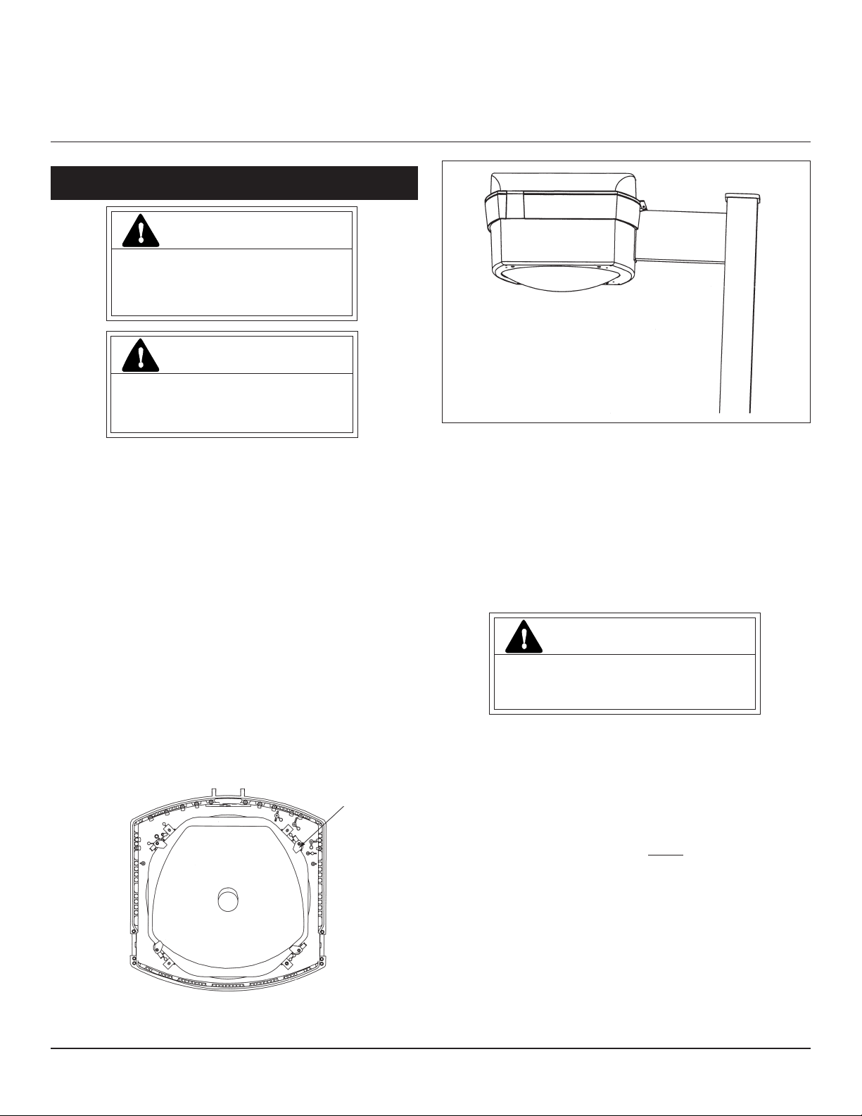
Criterion™ Medium Vertical Area
READ THOROUGHLY BEFORE INSTALLING
WARNING
Risk of electric shock
• Turn power off before servicing
– see instructions
WARNING
Risk of fire
• Use supply wire specified on
nameplate
GENERAL
This luminaire is designed for outdoor lighting
applications, and should not be used in areas of limited
ventilation, or in high ambient temperature enclosures.
Best results will be obtained if installed and maintained
according to the following recommendations.
UNPACKING
This luminaire has been properly packed so that no parts
should have been damaged during transit. Inspect to
confirm. Do not set unpacked unit on glass lens.
INSTRUCTIONS
1. Open the fixture cover and lock brace.
2. Remove socket holder from reflector noting socket position. Rotate retainer clips to a position off flange of the
reflector. (see figure 1)
3. Rotate reflector to desired position and rotate four retainer
clips from over flange.
4. Install Socket/lamp holder to proper position
(see Figure 7).
5. Close cover and latch.
MOUNTING
CAUTION
INSTALLATION
Follow installation instructions:
Reflector Rotation: Reflectors may be rotated such that
reflector is in any of four positions. This allows for
variations in beam aiming. In order to rotate the reflector,
the following procedure should be followed.
Reflector
Retainer Clips
Top View of Housing with Cover removed
Figure 1
These instructions do not purport to cover all details or variations in equipment nor to provide for every possible contingency to be met in connection with installation, operation or
maintenance. Should further information be desired or should particular problems arise which are not covered sufficiently for the purchaser’s purposes, the matter should be referred
to GE Lighting Solutions.
Note: Power leads should be pulled as mounting
parts are assembled, verifying that leads are free
and not pinched.
ARCHITECTURAL MOUNTING (ARM):
USE WITH SQUARE POLES PRE-DRILLED PER
FIGURE 2:
1. Install nut plate (see figure 3) inside pre-drilled pole.
Secure nut plate to inside of pole with screw provided.
2. Install the two (2) studs ensuring that they fully penetrate the nut plate.
3. Align upper and lower guides on inside of mounting arm
with their respective studs and slide it into place against
pole. Arm is tapered. Make sure that the short side of
arm is on top (see figure 4). Note: Wiring for unit should
be pulled through arm at this time.
4. Open Luminaire cover, remove SnapDrive™ electrical
system to reduce weight. (See instructions for correct
SnapDrive removal.)
Unit will fall if not installed properly
• Follow installation instructions
Page 2
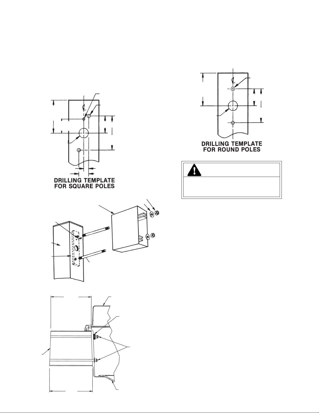
5. Install the luminaire and secure with flat washers and lock
nuts provided (see figure 4). Align the system as the nuts
are tightened. Spacer washers are supplied. Several
washers will be needed for the top stud. (Note: Wiring for
unit should be pulled through arm at this time)
6. Install SnapDrive (See below instruction)
Caution: Ensure that nuts fully engage the two
studs. Correct tightening of studs nuts is important to ensure proper function of mounting system. Torque nuts to 18-22 foot pounds
(24.4 -29.8 N•m).
.312 in. (8mm) DIA
HOLE
5.250 in.
(133mm)
MIN
1.812 in.
(46mm)
1.250 in. DIA
(32mm DIA)
HOLE
.438 in. (11mm) DIA
HOLE
2.196 in. (56mm)
4.392 in.
(112mm)
.656 in. (17mm)
1.312 in. (33mm)
OTHER MOUNTINGS
Round Pole Adapters are also available for use with
housings machined with a straight hole pattern.
Installation is similar to the Architectural Mounting.
Follow installation instructions
.438 in. (11mm)
5.250 in.
(133mm)
MIN
.750 in. DIA
(19MM
DIA)
HOLE
DIA
HOLE
2.719 in.
(69mm)
5.438 in.
(138mm)
CAUTION
Figure 2
(1/4-20) SCREW
SQUARE POLE
NUT PLATE
Figure 3
MOUNTING ARM
STUDS
SHORT
NUTS (3/8-16)
WASHERS
COVER
SPACER WASHERS
Unit will fall if not installed properly
• Follow installation instructions
WIRING
Make all electrical connections in accordance with
all applicable code requirements (National Electrical
Code, Canadian Electrical Code and applicable local
Codes).
The customer must provide strain relief for the incoming
power in the pole top.
1. Verify that supply voltage is correct by comparing it to
nameplate.
2. Route wire harness leads from luminaire through arm
and into top of pole. Connect wire harness to supply wire
and return to interior pole.
Supply wiring entering from pole to interior terminal
board must be routed through the wiring clips
(see figure 5). Wires must not touch the reflector.
3. Connect ground lead to the green lead, green ground
screw on housing or terminal block provided.
MOUNTING
ARM
Figure 4
LONG
GLASS
NUT AND
WASHERS
4. Install slotted grommet around supply wires for IP65
rating.
Page 3

SNAPDRIVE
Cover Brace
Dress incoming power
wiring into clips and then to
terminal board. Wiring must
not touch reflector.
Slotted Grommet
Install around
wires for IP65
rating
Figure 5
Incoming
wiring
Clips
Cover Brace
Figure 6
Clips
Snap
SnapDrive
SnapDrive
Retention
Retention
Hooks
Hooks
The SnapDrive is equipped with a multi-volt ballast.
Ballast has been wired to the voltage indicated on the
nameplate. If another voltage is desired, place the voltage
selection jumper onto the appropriate voltage position as
indicated on the wiring diagram on the SnapDrive ballast
cover. Optional features such as fusing and photocontrols
are voltage specific. Do not change jumper positions if
fixture is equipped with these features. This will damage
or destroy these optional parts and will void the safety
listing (UL, CUL, CSA, etc.) of the fixture.
Fuses have been sized to the wattage that was ordered.
Replace power fuses only with fuses of the same type and
ratings. Failure to do so may void the safety listing (UL,
CUL, CSA, etc.) of the fixture.
SNAPDRIVE REMOVAL AND INSTALLATION
To remove Snapdrive: with the power off, open cover by
releasing the two latches. Disconnect all wire harnesses
from SnapDrive. Press clip located at end of SnapDrive (see
figure 6). Swing SnapDrive forward and lift off the
SnapDrive retention hooks.
To install Snapdrive: with power off, open cover of unit.
Hang module on hooks (figure 6). Swing SnapDrive into
clip lifting slightly as Snapdrive is swung into place. An
audible snap should be heard which indicates the module
has seated. Replace wiring harnesses into proper receptacles.
LAMP INSTALLATION
CAUTION
Risk of burn
• Allow lamp/fixture to cool before
handling
WARNING
Risk of burn
• Do not touch operating luminaire
Use only the type and wattage lamps specified on nameplate. Observe lamp manufacturer’s recommendations and
restrictions on lamp operation, particularly ballast type,
burning position, etc.
Lamp Tightness-Mogul Base Lamp: The lamp should be
securely inserted to the NEMA-EEI specified torque of 35
inch-pounds (3.95 N•m), which is best achieved by very firm
tightening sufficient to fully depress and load the center
contact of the socket.
Refer to Figure 7 for the proper lamp socket position for
Metal Halide and High Pressure Sodium lamps.
MAINTENANCE AND CLEANING
It will occasionally be necessary to clean the outside of
the glass to maintain light levels. Frequency of cleaning will
depend on ambient dirt level and minimum light level that
is acceptable to the user. The glass should be washed in a
solution of warm water and any mild, nonabrasive household detergent, rinsed with clean water and wiped dry.
Should the optical assembly become dirty on the inside,
wipe the reflector and clean the refractor in the above
manner.
Page 4

The light output of a luminaire is dependent on the age of
the lamp. In applications where the light level is critical, it
may be desirable to replace lamps before they burn out. The
lamp manufacturer can provide data showing how the lamp
light output decreases with use.
METAL
HALIDE
HIGH
PRESSURE
SODIUM
LAMP SOCKET POSTION
Figure 7
g
GE Lighting Solutions • 1-888-MY-GE-LED • www.gelightingsolutions.com
GE Lighting Solutions is a subsidiary of the General Electric Company. Evolve and other trademarks belong to GE Lighting Solutions. The GE brand and logo are trademarks of the General Electric Company.
© 2011 GE Lighting Solutions. Information provided is subject to change without notice. All values are design or typical values when measured under laboratory conditions.
16943533----888
35-201578-2M (12/08)
 Loading...