


GDWT668V
GE GDWT668V, PDWT180V, PDWT380V, PDWT560V, PDWT565V Technical Service Manual
...
GE Appliances
Technical Service Guide
September 2011
Top-Control Stainless
Steel Tub Dishwashers
GDWT668V
GDWT768V
PDWT180V
PDWT380V
PDWT560V
PDWT565V
CDWT280V
CDWT980V
ZBD6920V
ZBD7920V
ZBD8920V
31-9221
GE Appliances
General Electric Company
Louisville, Kentucky 40225

IMPORTANT SAFETY NOTICE
The information in this service guide is intended for use by
individuals possessing adequate backgrounds of electrical,
electronic, and mechanical experience. Any attempt to repair a
major ap pli ance may result in personal injury and property
damage. The man u fac tur er or seller cannot be responsible for the
in ter pre ta tion of this in for ma tion, nor can it assume any liability in
connection with its use.
WARNING
To avoid personal injury, disconnect power before servicing
this prod uct . If electrical power is required for diagnosis or test
purposes, disconnect the power immediately after performing the
necessary checks.
RECONNECT ALL GROUNDING DEVICES
If grounding wires, screws, straps, clips, nuts, or washers used to
complete a path to ground are removed for service, they must be
returned to their original position and properly fastened.
GE Appliances
Copyright © 2011
All rights reserved. This service guide may not be reproduced in whole or in part
in any form without written permission from the General Electric Company.
– 2 –

Table of Contents
Active Vent ...........................................................................................................................................................................26
Bottom Door Seal..............................................................................................................................................................27
Center Wash Arm .............................................................................................................................................................28
Coarse Filter ........................................................................................................................................................................30
Component Locator Views ...........................................................................................................................................13
Control Board ......................................................................................................................................................................22
Control Board Connector Locator View .................................................................................................................16
Control Features ................................................................................................................................................................ 7
Control Thermal Cutout (TCO)......................................................................................................................................22
Consumer Purge of the Bulk Dispenser Tank ......................................................................................................21
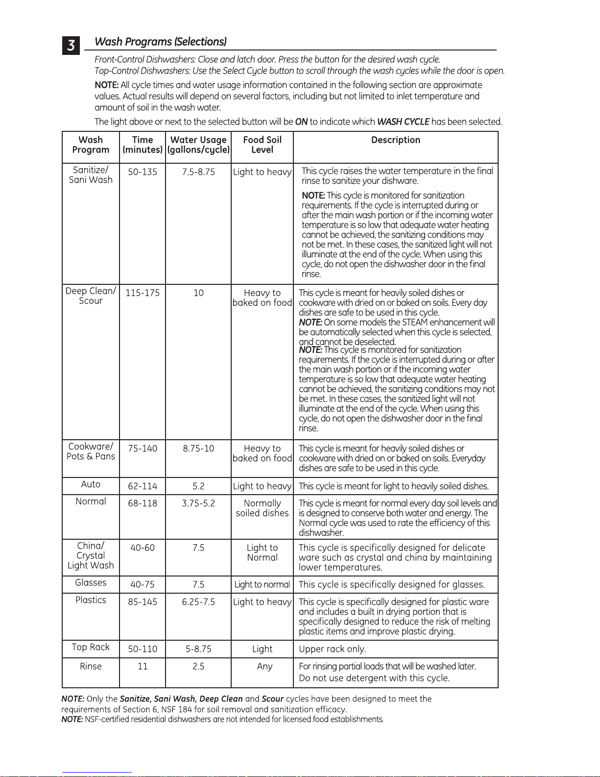
Cycle Chart ..........................................................................................................................................................................12
Cycles .....................................................................................................................................................................................11
Detergent/Rinse Module ................................................................................................................................................24
Dishwasher Components ..............................................................................................................................................17
Door Handle ........................................................................................................................................................................24
Door Switch Assembly ...................................................................................................................................................24
Drain Pump Assembly ....................................................................................................................................................35
Factory Test Mode ............................................................................................................................................................39
Fill Funnel ..............................................................................................................................................................................33
Fine Filter ..............................................................................................................................................................................29
Float Switch .........................................................................................................................................................................31
Heating Element ................................................................................................................................................................32
Inner Door Panel ...............................................................................................................................................................26
Introduction ......................................................................................................................................................................... 6
Lens .........................................................................................................................................................................................23
Lower Wash Arm ..............................................................................................................................................................28
Motor Pump Assembly ...................................................................................................................................................35
Nomenclature .................................................................................................................................................................... 5
Outer Door Panel ..............................................................................................................................................................17
Schematics and Wiring Diagrams ............................................................................................................................40
Service Mode ......................................................................................................................................................................37
– 3 –
(Continued next page)

SmartDispenseTM ...............................................................................................................................................................18
Sump Filter ...........................................................................................................................................................................29
Tactile Switch ......................................................................................................................................................................23
Troubleshooting ...............................................................................................................................................................37
Tub Gasket ...........................................................................................................................................................................27
Tub Thermal Cutout (TCO) .............................................................................................................................................36
Turbidity Sensor ................................................................................................................................................................31
Upper Wash Arm ..............................................................................................................................................................28
Vent Fan ................................................................................................................................................................................25
Warranty ..............................................................................................................................................................................41
Water Hardness Test and Calibration .....................................................................................................................17
Water Inlet Valve ...............................................................................................................................................................33
– 4 –
Model Number
Product Type
GDW = GE Long Door
PDW = Profi le
CDW = GE Café
Top Control
T = Top Control
Nomenclature
G D W T 6 6 8 V B B
Exterior Color
BB = Black
CC = Bisque
SS = Stainless Steel
WW = White
Feature Pack
Nomenclature
Access Panel
The nomenclature plate is lo cat ed on
the left side of the tub wall, inside the
door jamb.
The mini-manual is located behind
the access panel.
Door
8 = Stainless Door
Model Year Designator
Handle/Control Location
0 = Latch/Front Control
6 = Recessed/Top Control
8 = Towel Bar/Top Control
Serial Number
The fi rst two characters of the serial number
identify the month and year of manufacture.
Example: VV123456S = November, 2011
V - NOV
Z - DEC
A - JAN
B - FEB
F - MAR
G - APR
H - MAY
L - JUN
M - JUL
R - AUG
S - SEP
T - OCT
2011 - V
2010 - T
2009 - S
2008 - R
2007 - M
2006 - L
2005 - H
2004 - G
2003 - F
2002 - D
2001 - A
2000 - Z
The letter des ig nat ing
the year re peats every
12 years.
Example:
V - 2011
V - 1999
V - 1987
– 5 –
Introduction
New Features and Benefi ts
• Five-stage fi ltration with Piranha™ hard food disposer
• Dedicated silverware jets
• Steam PreWash
• Fan assist dry with heated option and ActiveVent
• Fifty-two dBA sound level
• ENERGY STAR® qualifi ed and CEE Tier II rated
• SmartDispense™ (only on models GDWT7XX, PDWT3XX, PDWT5XX, CDWT980, and ZBD89XX)
Weights and Dimensions
Approximate Shipping Weight .........................................................................................................................................115 lb
Net Weight .................................................................................................................................................................................110 lb
Overall Height ..........................................................................................................................................................................34 in.
Height with Legs Extended ................................................................................................................................................35 in.
Overall Depth ...........................................................................................................................................................................24
Overall Width ............................................................................................................................................................................24 in.
3
/4 in.
– 6 –
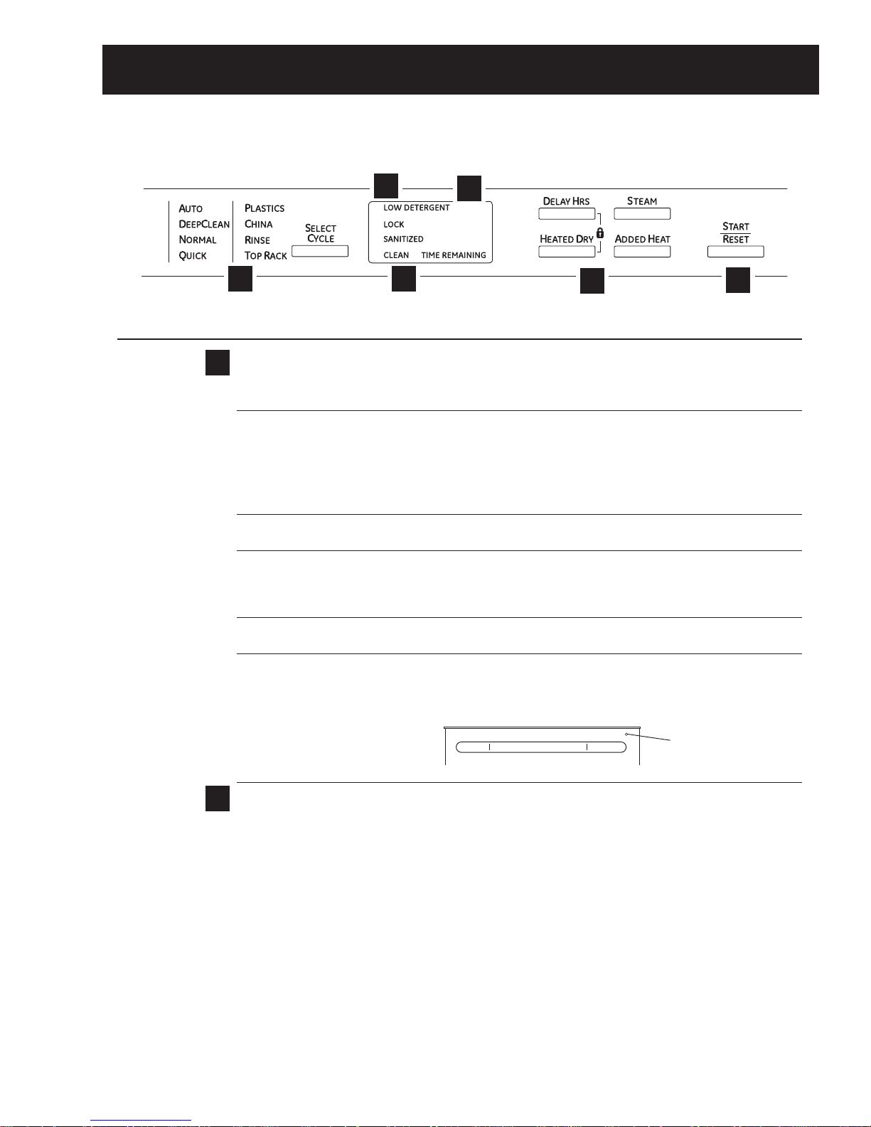
Control Features
Throughout this manual, features and appearance may vary from your model.
Top-Control Dishwashers
3
Control Settings
Status Indicator Lights (Indicators vary by models)
1
The Status display tells you what is happening while the dishwasher is in operation and may flash, indicating
a malfunction. The lights will come ON indicating the sequence of the dishwasher operation.
LOW DETERGENT Displayed when the SmartDispense
1
6
dishwasher detergent.
NOTE:If you are not using SmartDispense
LED light off, press the ADDED HEAT button 5 times within 3 seconds. You will hear 3
beeps; then the light will go off. You can turn the light back on by pressing the ADDED
HEAT button 5 times within 3 seconds.
SENSING Displayed while the Clean Sensor
of water. The dishwasher will adjust the selected cycle to achieve optimal performance.
SANITIZED Displayed at the end of the cycle when SANITIZE has been selected and the dishwasher
has met the requirements for sanitization. See SANITIZE, below, for complete cycle
description. Opening the door or pressing any key while the door is closed and latched
will turn off the light.
CLEAN Displayed when a wash cycle is complete. Refer to Item 6, page 9, for further
explanation of clean light operation
CYCLE ST ATUS The cycle status indicator light is located on the right side of the dishwasher, above the
INDICAT OR handle. This light comes on as amber while the selected cycle is running. The light turns
to green when the selected cycle is complete. The light stays ON as green as a reminder
that the dishes are clean until the door is opened or until another cycle is selected.
2
4
TM
needs to be refilled with liquid or gel automatic
TM
and you want to turn the LOW DETERGENT
TM
is measuring the amount of soil and temperature
5
Time Remaining Display (on some models)
2
During operation, the display shows the minutes remaining until the cycle is complete. The display may
adjust the remaining time while the Sensing light is on. The time displayed at the start of each cycle may
change from the factory setting as the unit customizes itself to home use. During a delay start, the display
will show hours of time remaining until the cycle starts.
NOTE: This dishwasher is equipped with CleanSensor
6
cycle length and time may vary depending on soil and water temperature conditions.
– 7 –
Cycle Status Indicator Light
TM
with automatic temperature control; therefore,
(Continued next page)
– 8 –
(Continued next page)
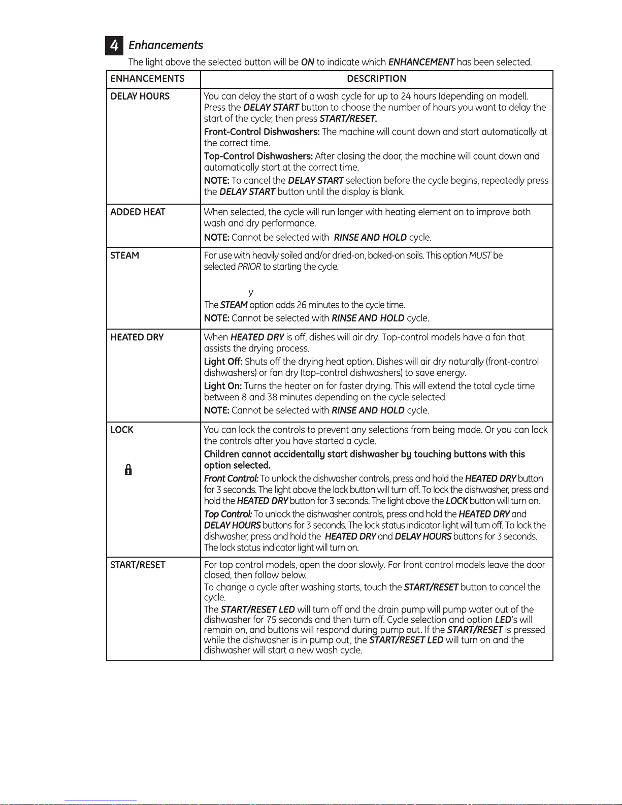
The STEAM option will use the heater to
increase the temperature of the water. The circulation pump will turn off
periodicall , allowing water to drip onto the hot calrod which will create steam.
– 9 –
(Continued next page)
Start
5
– 10 –

Cycles
Auto Hot Start:
Auto Hot Start is initiated by the control board when it senses water temperature is below 80°F. If the water
is below 80°F after prewash, the unit circulates for 1 to 5 minutes (depending on the cycle selected) and then
drains for 75 seconds. This procedure repeats up to 4 times or until the water reaches 80°F.
Added Heat:
The added heat option differs for the various cycles. Some cycles will not be modifi ed, some cycles will
increase the calrod time, and some cycles will get additional segments added (e.g., AUTO has 6 segments
without added heat and 9 segments with added heat).
Heated Dry:
During HEATED DRY, the heater cycles at a rate of 60 seconds on and 51 seconds off.
Cycle Explanations and Exceptions:
• Turbidity Response is used during the SANITIZED, NORMAL, and AUTO cycles only.
• Timed cycles can change depending on the water temperature. If the minimum temperature is not met,
an extended time is added until the temperature is met or the time expires.
• Partial Drain and Fill Algorithm is used during NORMAL and AUTO cycles only.
• Auto Hot Start may cause the fi rst prewash to repeat up to 4 times.
• Disabling STEAM will shorten the cycle time.
• If STEAM is selected during NORMAL or AUTO cycles, turbidity response is ignored, and cycle defaults to
the heavy soil algorithm.
• HEATED DRY takes 34 minutes for the NORMAL cycle while the other cycles vary to as long as 60
minutes for PLASTICS. There is no HEATED DRY for the RINSE cycle.
• Drain Overlap is a short period when both the wash and drain pumps run simultaneously as the
circulation cycle ends and draining begins.
• Drain Pause is a short period between the circulation cycle ending and the drain starting.
• Extend Times enables both the circulation pump and heater to operate simultaneously.
Turbidity Response
The turbidity response is measured in DC volts. Four to 5 VDC registers light soil and a shorter wash cycle,
while 0 to 2 VDC registers heavy soil and a longer wash cycle. SANITIZED wash measures the turbidity
response during the third prewash cycle and adjusts the time based on these measurements. NORMAL wash
measures the turbidity response during the fi rst prewash and the prewash before the main wash. If a clean
response is measured during the fi rst prewash, the cycle advances directly to the main wash with no drain or
fi ll. If a clean response is measured during the prewash before the main wash, the control shortens the active
heater time.
– 11 –
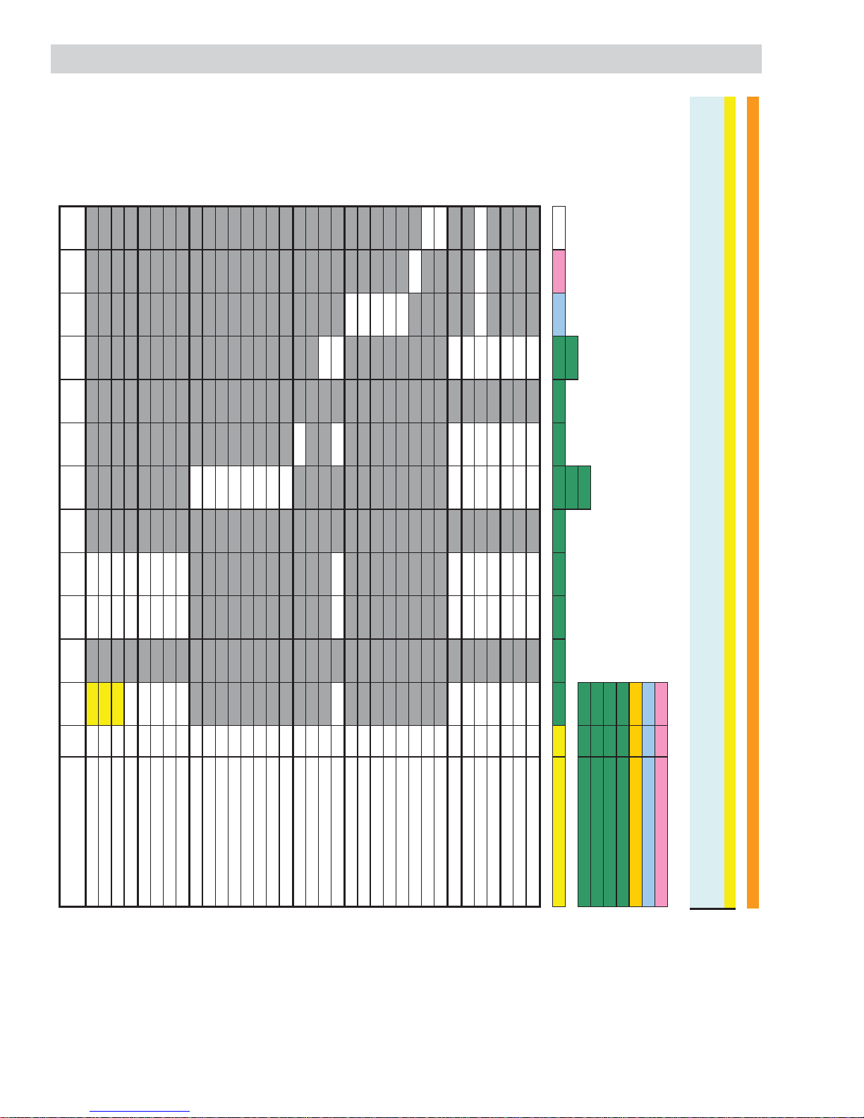
Normal Cycle PW1* PW2 PW3 PW4 PW5 MW** PR 1 PR2 FR Dry
Cool-
Down
Turb DOE [Vdc] 3.1 - 5.0 5.0 - -
Turb MIN [Vdc] 2.1 - 5.0 5.0 - -
Turb MED [Vdc] 2.1 - 5.0 5.0 - -
Turb MAX [Vdc] 1.0 - 0.1 0.1 - -
Time DOE [min] 5 - - 10 - -
Time MIN [min] 5 - - 10 - -
Time MED [min] 5 - - 10 - -
Time MAX [min] 1 - 3 10 - -
MW DOE Circulate Time [min] - - 30 -
MW DOE Heater Time [min] - - 28 -
MW MIN Circulat e Time [min] - - 30 -
MW MIN Heater Time [min] - - 27 -
MW MED Circulate Time [min] - - 30 -
MW MED Heater Time [min] - - 27 -
MW MAX Circulate Time [min] - - 30 -
MW MAX Heater Time [min] - - 30 -
Pre-Rinse 1 (PR 1) [min] - - 7 -
Pre-Rinse 2 (PR 2) [min] - - -
Final Rinse (FR) [min] - - - 6
Heater On Time [min] 0 - 0 10 - y** 0 - 5
Dry Time (Total Time) w/ HD [min] - - - 34
HD - Initial ON Time [min[ - - - 4
HD - Pulse OFF Time [sec] - - - 105
HD - Pulse ON Time [sec] - - - 75
Dry Time (Tot al Time) w/o HD [ min] - - - 0
Cool-Down Time [min] - - - 14
Fan Time w/ Heated Dry [min] - - - 48
W/ Out Heated Dry [min] - - - 14
Pause time (circ t o drain) [sec] 0 - 15 0 - 15 0 - 15
Fill Time (low flow water valve) [sec] 62 - 16 62 - 21 62 - 23
Fill Time (high flow water valve) [sec] 46 - 13 46 - 15 46 - 17
Drain Time [sec] 7 - 75 10 - 75 11 - 105
Max Temp Limit [F] - - - 158 - 158 - - 158
Min Temp Limit [F] ----- 120 - - 120
Extend Time [min] 0 - 0 0 - 5 0 - 5
Total Primiti ve [min] 6.15 - 4.52 11.20 - 31.25 8.22 - 8.13 34.00 14.00
31.60 13.13
Shortest Cycle [min] 67.63 36.60
Longest Cycle [min] 93.82
ART (Max) [min] 69.82
ART (Med) [min] 69.82
AH-MW [min] NA
HTD [min] 34.00
CD [min] 14.00
* IF on PW1 the turbidity is greater than the DOE response the cycle will skip the drain portion of PW1, completely skip PW3, PW4, and skip the fill into MW…effectively merging PW1 and MW circ
* IF on PW1 the turbidity is less than the DOE response but greater than the MI N response the cycle will skip PW3, PW4.
** Circulation and Heater ON times for Main Wash are determined by the turb valies in PW1
*** Detergent/Rinse Aid relay will be activated in FR
NOTE: ****PW2, PW5, PR2 intent ionally left blank due to separating the added heat functionality into its own cycle definition table. See Norm_Auto+AH cycle table.***
Cycle Chart
Fan
– 12 –
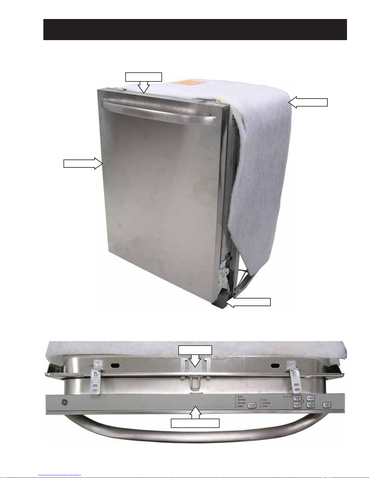
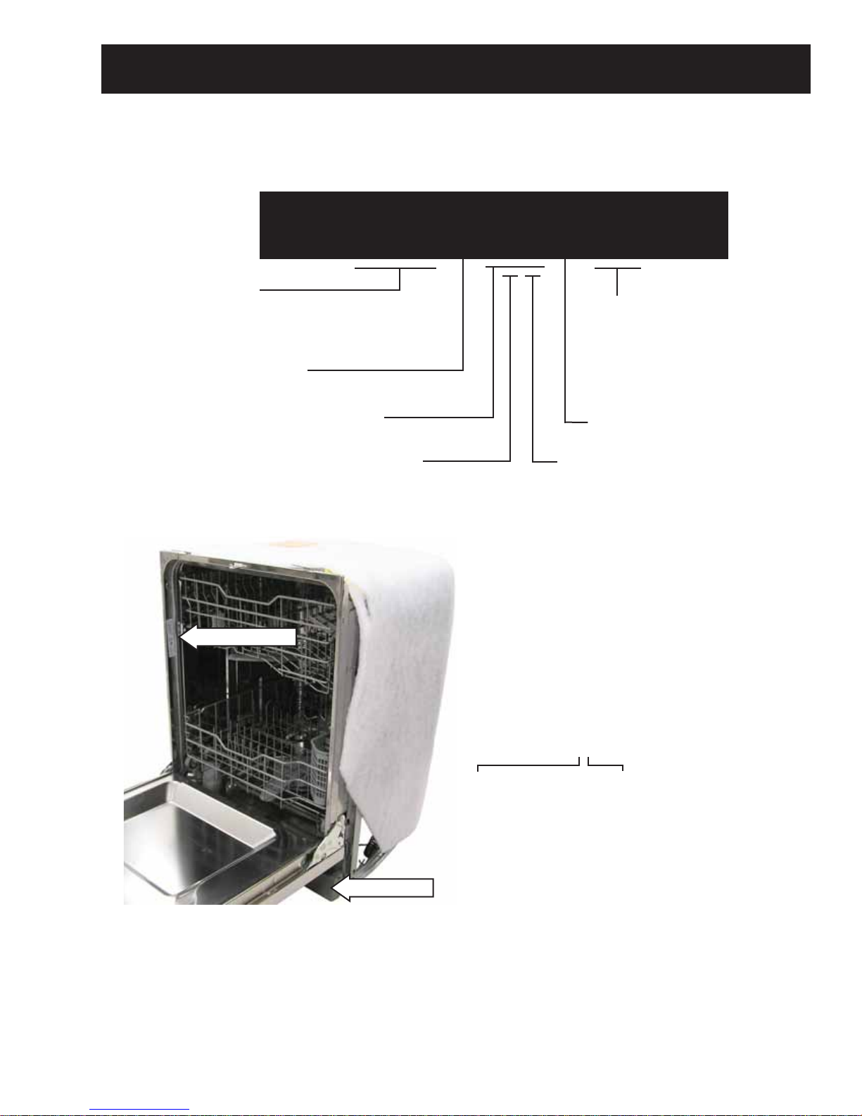
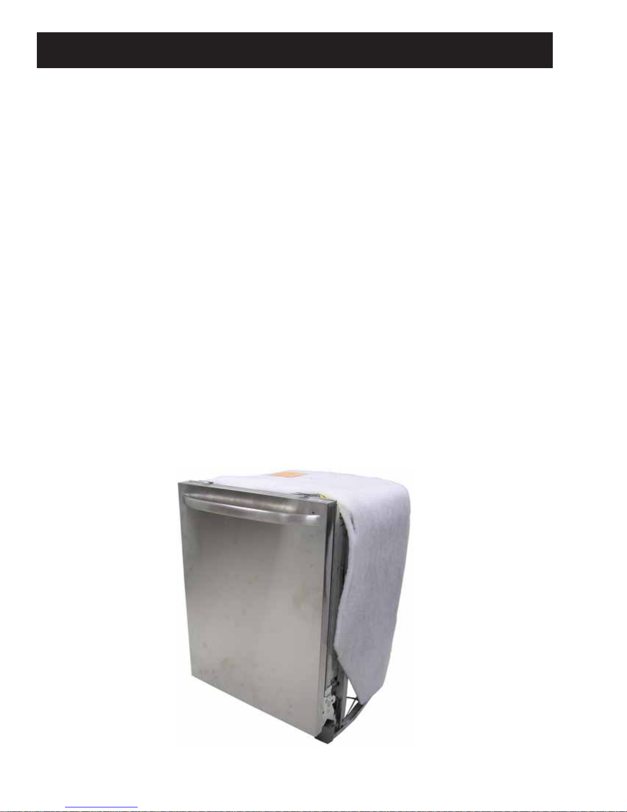
Front View
Door Panel
Component Locator Views
Control Panel
Insulation
Control Panel View
Access Panel
Door Latch
Control Assembly
(Continued next page)
– 13 –
 Loading...