


FVR-C9S-2UX
Instruction Manual
FVR-C9S-2UX Drive Series
Three-phase 230 VAC Input Type
1

FVR-C9S-2UX
CAUTION
•Make sure that you read this instruction manual thoroughly before installing, wiring, operating and inspecting this drive.
•Please make sure that this instruction manual accompanies the drive to the end user.
•Keep this instruction manual so that it will always be available for the duration of the drive’s operating life.
•Product specifications are subject to change without notice.
2
FVR-C9S-2UX
Thank you for purchasing the Fuji “FVR-C9S” drive, marketed by GE Fuji Drives USA, Inc. This instruction manual is included with the drive and equipment and is provided for the convenience of the end user. Please be sure it accompanies the drive.
CONTENTS |
|
|
0. |
Safety Precautions .................................... |
4 |
1. |
Inspection Upon Receipt .......................... |
6 |
2. |
Part Names ............................................... |
7 |
3. |
Warning and Caution ................................ |
7 |
4. |
Specifications ........................................... |
8 |
5. |
External Dimensions ............................... |
10 |
6. |
Installation Instructions ........................... |
13 |
7. |
Wiring ...................................................... |
13 |
8. |
Basic Wiring Diagrams ............................ |
15 |
9. |
Application of Wiring and Equipment ..... |
17 |
10. |
Terminal Function Explanation ................ |
18 |
11. |
Operation ................................................ |
20 |
12. |
Keypad Panel .......................................... |
22 |
13. |
Function Explanation .............................. |
24 |
14. |
Protective Functions ............................... |
35 |
15. |
Warranty Parts and Service .................... |
36 |
3
FVR-C9S-2UX
0. Safety Precautions
Before carrying out installation, wiring, maintenance or inspection of the drive, read this instruction manual thoroughly to gain a full understanding of the correct operation procedures. Make sure that you have read all product details, safety information, warnings and cautions before use. The following classifications for warnings and cautions are used throughout this manual.
WARNING:
Do not let any scraps of thread, paper, sawdust, dirt, metal shavings or other foreign objects get inside the drive or onto the cooling fins, otherwise fire or problems with operation may result.
Do not install and operate the drive if it is damaged or if some of the parts are missing. Doing so may result in severe personal injury.
Do not touch the drive cooling fin because the cooling fin reaches high temperatures during operation, otherwise personal injury may result.
Denotes operating procedures and practices that may result in severe injury or loss of life if not correctly followed.
CAUTION:
Denotes operating procedures and practices that, if not strictly observed, may result in personal injury or damage to the equipment.
WIRING
WARNING:
FIRE AND ELECTRIC SHOCK HAZARD.
When connecting the drive to a power supply, be sure to connect it via a circuit breaker, a leakage current breaker or a fuse, otherwise fires may result.
WARNING:
FIRE AND PERSONAL INJURY HAZARD
This drive is designed for variable-speed operation of three-phase induction motors. It cannot be used with single-phase motors or for any other applications, otherwise fire may result.
The drive cannot be used by itself for elevators, life-preservation equipment or other equipment which is directly related to human safety. In such situations, sufficient consideration should be given to overall system configuration, not just to the drive, otherwise serious accidents could result.
INSTALLATION
WARNING:
FIRE AND PERSONAL INJURY HAZARD
Install the drive to a non-flammable surface such as a metal surface, otherwise fires may result.
Do not place the drive near flammable materials, otherwise fires may result.
Do not hold the drive by its cover when transporting. The drive could be damaged and cause injury to personnel.
AC input fuses are required to validate the UL listing of this device.
Use only fuses and circuit breakers with rated capacities that are suitable for use with the drive. Failure to do so may result in fire.
Connect the drive with a secure ground, otherwise electric shocks or fires may result.
Wiring work should only be carried out by suitably qualified personnel, otherwise electric shocks may result.
Make absolutely sure that the power supply is turned off (open) before wiring, otherwise electric shocks may result.
Wiring work should only be carried out after the drive has been installed, otherwise electric shocks or injury may result.
4
FVR-C9S-2UX
CAUTION:
Check that the phase and voltage of the AC power supply being connected matches the input phase and rated input voltage of the drive. Using an improper power supply may cause injury or damage to the equipment.
Do not connect AC power to the output terminals (U, V, W) otherwise injury may result.
The drive, motor and wiring produce electromagnetic noise during operation. Make sure that this does not interfere with the operation of sensors or other equipment nearby, otherwise accidents may result.
OPERATION
WARNING:
ELECTRIC SHOCK HAZARD
Always install the drive cover before turning on the power supply. In addition, do not remove the drive cover while the power is on. Failure to observe these precautions may result in electric shocks.
Do not operate any of the switches with wet hands, otherwise electric shocks may result.
WARNING:
FIRE AND PERSONAL INJURY HAZARD
If the retry function has been activated and a trip occurs, the drive will restart automatically depending on the cause of the trip. Make sure that the system is set up properly so that there will be no danger to personnel when the drive starts.
The STOP key is only effective when keypad panel operation has been selected in the function settings. A separate switch should be installed for emergency stopping purposes.
If an alarm reset is carried out while a run signal (FWD/REV) is being input, the drive will suddenly restart. Always check that the run signal is not being input before carrying out the alarm reset, otherwise accidents may occur.
Never touch the drive terminals while the power is fed to the drive, regardless of whether the drive is running or not.
CAUTION:
Do not touch the cooling fins, as they become hot during drive operation.
Because it is relatively easy to set the drive to high speed operation, be sure to check the capacity of the motor and the equipment being operated before changing the drive function setting.
The drive braking function cannot be substituted for mechanical means. Attempting to do so may result in injury.
MAINTENANCE, INSPECTION AND PART REPLACEMENT
WARNING:
ELECTRIC SHOCK HAZARD
Wait at least five minutes after turning off the power before carrying out inspection. Check that the charge indication lamp has gone out. Do not touch the drive parts if the lamp is still lit, otherwise electric shocks may result.
Maintenance, inspection and parts replacement should only be carried out by suitably qualified personnel. Remove any metallic accessories such as watches and rings before starting work, and use only properly insulated tools, otherwise electric shocks may result.
DISPOSAL
CAUTION
Disposal of the drive should be entrusted to a suitably-qualified disposal agency, otherwise injury may result.
PACKING
CAUTION
Do not stand or sit on the drive as injury may result.
The number of packing cartons that can be stacked together is printed on the packing container. Do not stack the containers any higher than this or injury may result.
5

FVR-C9S-2UX
UL/CSA
WARNING / AVERTISSEMENT
Hazard of electrical shock. Disconnect incoming power before working on this control.
Risque de choc electrique. Couper l’alimentation avant le depannage de sette commande.
More than one live circuit. See diagram. Cet equipment renferme plusieurs circuits sous tension. Voir le schema
CAUTION ATTENTION
Dangerous voltage exists until charge light is off. Prede tensions dangereuses tant que le voyant n’est pas eteint.
Suitable for use on a circuit capable of delivering not more than 5,000 rms symmetrical amperes. 240V maximum.
•Use 60/75° C copper wire only.
•Use Class 1 wire only.
•Open type equipment
•Tightening torque and wire range for field wiring terminals are as follows:
Model |
Required |
Wire |
|
torque (N.m) |
range |
FVRF12C9S-2UX |
0.98 |
14 |
FVRF25C9S-2UX |
0.98 |
14 |
FVRF50C9S-2UX |
0.98 |
14 |
FVR001C9S-2UX |
0.98 |
14 |
FVR002C9S-2UX |
0.98 |
14 |
FVR003C9S-2UX |
0.98 |
14 |
FVR005C9S-2UX |
1.777 |
12 |
Control board |
|
|
terminal |
0.7 |
24 |
Use the listed quick-acting fuse in series. Factory recommendation is a Bussman type, JKS or equivalent. Fuses are required to validate the UL and CSA listings.
Model |
Dist. fuse size,600V |
FVRF12C9S-2UX 5
FVRF25C9S-2UX 5
FVRF50C9S-2UX 5
FVR001C9S-2UX 10
FVR002C9S-2UX 20
FVR003C9S-2UX 20
FVR005C9S-2UX 30
Field wiring connection shall be made by a UL listed and CSA Certified closed-loop terminal connector sized for the wire gauge involved.
Connector must be fixed using the crimp tool specified by the connector manufacturer.
OTHER
WARNING:
FIRE AND PERSONAL INJURY HAZARD
Do not carry out any modifications to the drive. Doing so may result in electric shock and injury.
GENERAL CAUTION
All of the illustrations in this instruction manual show the drive with the covers and other protective equipment removed in order to facilitate explanation of detailed parts of the drive. Be absolutely sure to return all covers and protective equipment to the prescribed positions before operating the drive, and make sure that all operations are carried out in accordance with the instructions in this manual.
1. Inspection Upon Receipt
Please inspect the following items upon receipt of your drive.
•Check the name plate to insure the specifications correspond to those ordered.
•Inspect the unit for damage which may have occurred during shipping.
If you have any problems or questions regarding the drive, please contact the nearest Fuji sales office or the distributor where the unit was purchased.
Nameplate
|
|
|
|
|
|
|
|
|
|
1 |
||||
TYPE |
|
|
|
|
|
|
|
|
|
|||||
|
|
|
FVRF 12C9S-2UX |
|
|
|
|
|
||||||
|
|
|
|
|
|
|
||||||||
SOURCE |
|
|
|
|
|
|
|
|
2 3 4 |
|||||
|
|
3PH 200-230V 0.9A 50/60 HZ |
||||||||||||
|
|
|
|
|
||||||||||
OUTPUT |
|
|
|
|
5 6 7 |
|||||||||
3PH 200-230 0.7A 1/8HP 1-120HZ |
||||||||||||||
|
|
|||||||||||||
SER. NO. |
|
|
|
|
|
|
8 |
|||||||
|
|
|
|
|
||||||||||
|
|
|
|
|
|
|
|
|
|
|
|
|
|
|
|
|
|
Fuji Electric Co. Inc. Japan |
|
|
|
|
|
|
|
|
|
||
|
|
|
|
|
|
|
|
|
|
|
|
|
|
|
6

1. Type
Drive Series
FVR-C9S-2UX
3. Warning and Caution
F V R F 2 5 C 9 S 2 U X
 Power Series: 230V UX Series Applicable motor output (Hp)
2.Phase: 3PH - three-phase
3.Voltage range: 200V - 230V - AC200V Series
4.Frequency: 50/60Hz
5.Rated output capacity
6.Rated output current
7.Output frequency range: 1- 120 Hz
8.Serial No.
2. Part Names
4
2
PRG |
RUN |
|
RESET |
||
|
||
FUNC |
STOP |
|
DATA |
||
|
FVR-C9S
3
1
CLOSED OPEN
 4
4
5
Improper wiring will result in damage to, and failure of the unit. Please carefully note the items listed below, and use the unit as indicated.
WARNING AND CAUTION
1.Do not impress power supply voltage that exceeds the standard specification voltage permissible fluctuation. (Permissible voltage: AC200V - 230V)
2.Do not connect power supply to the drive output terminals (U, V, W). Connect power supply only to the power terminals (L1, L2 and L3)
3.Whenever removing the drive cover, always switch off the power supply. Do not switch on the power supply to the drive with the drive cover removed.
4.Do not touch the live part until the CRG lamp located above the main circuit terminals goes out.
5.Avoid using a magnetic contactor (ON/ OFF) installed in the line side of the drive for RUN and STOP. Use the FWD-CM (forward) and REV-CM (reverse) terminals for RUN and STOP.
6.Do not connect a power factor correcting capacitor to the output side of the drive.
7.Do not perform a megger test between the drive terminals or on the control circuit terminals.
1.Drive Cover
2.Keypad Panel
3.Frequency Setting VR
4.Mounting Screw Holes
5.Drive Cover Screw
7
FVR-C9S-2UX
4. Specifications
Type (FVR _ _ _ C9S-2UX) |
|
|
F12 |
|
F25 |
F50 |
001 |
|
002 |
|
003 |
|
005 |
|
|
Applicable motor output1 |
|
[Hp] |
1/8 |
|
1/4 |
1/2 |
1 |
|
2 |
|
3 |
|
5 |
|
|
|
Rated capacity2 |
|
[kVA] |
0.28 |
|
0.56 |
1.0 |
1.6 |
|
2.8 |
|
4.0 |
|
6.6 |
|
|
Voltage |
|
[V] |
Three-phase 200-230V 50/60 Hz (Output voltage is proportional |
|
||||||||||
|
|
|
|
to input voltage) |
|
|
|
|
|
|
|
|
|
||
Output Rating |
Rated current |
|
[A] |
0.7 |
|
1.4 |
2.5 |
4.0 |
|
7.0 |
|
10.0 |
|
16.5 |
|
|
Overload current rating |
|
150% 1 min. |
|
|
|
|
|
|
|
|
|
|||
|
Rated frequency |
|
[Hz] |
50/60 Hz |
|
|
|
|
|
|
|
|
|
|
|
|
Phase, voltage, frequency |
|
Three-phase 200-230V 50/60 Hz |
|
|
|
|
|
|
||||||
|
Allowable variation in |
|
Voltage: =10 - 15% Frequency: 15% (Imbalance in power |
|
|
||||||||||
Input power |
voltage/frequency |
|
supply voltage: 3%) |
|
|
|
|
|
|
|
|
||||
supply |
Instantaneous voltage drop |
|
Drive is kept running if voltage is 165V or more. If voltage drops |
|
|||||||||||
|
withstanding capacity |
|
more than 165V from rated voltage, drive is run for 15ms.3 |
|
|
||||||||||
|
Required power supply |
[kVA] |
0.3 |
|
0.7 |
1.2 |
1.8 |
|
3.2 |
|
4.5 |
|
7.3 |
|
|
|
capacity |
|
|
|
|
|
|
||||||||
|
|
|
|
|
|
|
|
|
|
|
|
|
|
|
|
|
Adjustment |
Max. freq.4 |
[Hz] |
50-120 Hz Setting variable (in increments of 1 Hz) |
|
|
|||||||||
|
|
Base freq. |
[Hz] |
50-120 Hz Setting variable (in increments of 1 Hz) |
|
|
|||||||||
|
Starting freq. |
[Hz] |
1-6 Hz Setting variable (in increments of 1 Hz) |
|
|
|
|
||||||||
Output |
Accuracy |
|
|
Analog setting: ±1.0% of max. frequency (25±10°C) |
|
|
|||||||||
frequency |
|
|
|
Digital setting: ±0.01% of max. frequency (-10 - +50°C) |
|
|
|||||||||
|
Setting resolution |
|
Analog setting:1/255 of max. frequency |
|
|
|
|
|
|
||||||
|
|
|
|
|
|
(ex. 0.25 Hz / 60 Hz, 0.5 Hz / 120 Hz) |
|
|
|
|
|||||
|
|
|
|
Digital Setting: 0.1 Hz (99.9 Hz max) 1 Hz (100-120 Hz) |
|
|
|||||||||
|
Control method |
|
|
Sine wave PWM control |
|
|
|
|
|
|
|
|
|||
|
|
|
|
(Extremely low noise by high frequency carrier) |
|
|
|
|
|||||||
Control |
Operation |
|
|
Keypad operation: Operation control by RUN/STOP keys |
|
|
|||||||||
|
|
|
|
Terminal strip: |
Forward command. Reverse command. |
|
|
||||||||
|
|
|
|
|
|
|
Coast-to-stop command. Reset. |
|
|
||||||
|
|
|
|
|
|
|
External alarm. |
|
|
|
|
|
|
||
1) "Applicable motor" indicates a standard 4-pole motor. |
|
|
|
|
|
|
|
|
C92-2-13 |
||||||
|
|
|
|
|
|
|
|
|
|
||||||
2)"Rated capacity" indicates a capacity at 230V rating.
3)This applies to the case where momentary power failure occurs under such conditions that rated voltage is inputted and load factor is 85%.
4)Shows the case where an applicable motor equipped with an AC reactor (option) on the input side is used.
8
FVR-C9S-2UX
Type (FVR _ _ _ C9S-2UX) |
|
F12 |
|
F25 |
F50 |
|
001 |
002 |
|
003 |
|
005 |
|
Applicable motor output1 |
[Hp] |
1/8 |
|
1/4 |
1/2 |
|
1 |
2 |
|
3 |
|
5 |
|
|
Frequency setting |
|
Key operation: |
Setting with UP/DOWN keys |
|
|
|
||||||
|
|
|
Potentiometer: |
Terminal for 1-5K ohm VR is provided |
|
||||||||
|
|
|
Analog signal: |
0-5 VDC 0-10 VDC |
|
|
|
||||||
|
|
|
|
|
|
(input resistance = 22k ohm) |
|
|
|
||||
|
Display |
Run mode |
Output frequency is displayed. (3 digit LED) |
|
|
|
|||||||
|
|
Fault mode |
Cause of fault is displayed. |
|
|
|
|
|
|
||||
|
|
Other |
LED comes on with charging voltage applied. |
|
|
|
|||||||
|
Acceleration/Deceleration time |
0-60s (Variable setting) Acceleration time and deceleration |
|
||||||||||
Control |
|
|
time can be set independently. |
|
|
|
|
|
|||||
|
Voltage frequency characteristics |
Setting of maximum frequency/base frequency is variable. |
|
||||||||||
|
Restart after momentary power failure |
"Automatic restart" setting makes it possible to keep motor |
|
||||||||||
|
|
|
running and restart drive in case of a momentary power failure. |
||||||||||
|
High Limiter & Low Limiter |
Upper limit and lower limit of frequency can be set. |
|
|
|
||||||||
|
Bias setting |
|
Bias setting is possible with respect to analog frequency setting. |
||||||||||
|
Jump frequency |
|
Three jump points and one jump width can be set. |
|
|
|
|||||||
|
Torque boost |
|
Setting variable in 32 steps. |
|
|
|
|
|
|
||||
|
Starting torque |
[%] |
150% for 60 seconds |
|
|
|
|
|
|
||||
|
Braking torque5 |
[%] |
150% 1 min. |
100% 1 min. |
50% 1 min. |
|
30% 1 min. |
||||||
Braking |
DC brake |
|
Brake starting frequency: 3 Hz (fixed) |
|
|
|
|||||||
|
|
|
Setting of braking current / braking time is variable. |
|
|||||||||
|
Overload |
|
Detects overload current and stops drive. |
|
|
|
|||||||
|
Momentary overcurrent |
|
Protects drive In case of ground fault (detects at start) and |
|
|||||||||
|
|
|
short circuit of output circuit. |
|
|
|
|
|
|
||||
|
Overvoltage |
|
Detects overvoltage of DC bus and stops drive. |
|
|
|
|||||||
Protection |
Overheating of cooling element |
Detects abnormal temp. rise of cooling element and stops drive. |
|||||||||||
|
Motor protection |
|
Protects standard 4-pole motor and forced-air cooled motor by |
||||||||||
|
|
|
means of electronic thermal overload relay. |
|
|
|
|||||||
|
Alarm protection |
|
Outputs contact signal in case of a trip for protection |
|
|||||||||
|
|
|
(1c contact capacity: AC250V |
0.3A |
cos = 0.3) |
|
|
|
|||||
|
Installation location |
|
Indoor at an altitude of 3283 feet (1000m) or less and free of |
|
|||||||||
|
|
|
dust, corrosive gas and oil mist. |
|
|
|
|
|
|||||
|
Ambient temperature |
|
-10 to 50°C |
|
|
|
|
|
|
|
|
|
|
|
Ambient humidity |
|
20 -90% RH (There shall be no dew condensation) |
|
|
|
|||||||
Environment |
Vibration |
|
19 feet/s2 (5.9m/s2) or less |
|
|
|
|
|
|
||||
|
|
|
Vibration frequency: 5 - 55 Hz |
|
|
|
|
|
|
||||
|
Storage temperature |
|
-25 to 65°C |
|
|
|
|
|
|
|
|
|
|
|
Atmospheric pressure |
|
Operation/storage: min 900 mb (equivalent to 3283 feet (1000m) |
||||||||||
|
|
|
Transport: min 660 mb (equivalent to 10720 feet (3265m) |
|
|||||||||
|
Enclosure |
|
IP20 |
|
|
|
|
|
|
|
|
|
|
Cooling method |
|
|
Self-cooling |
|
Forced-air cooling |
|
|||||||
5) This indicates average braking torque of a single motor. (Value varies according to motor efficiency.)
9
FVR-C9S-2UX
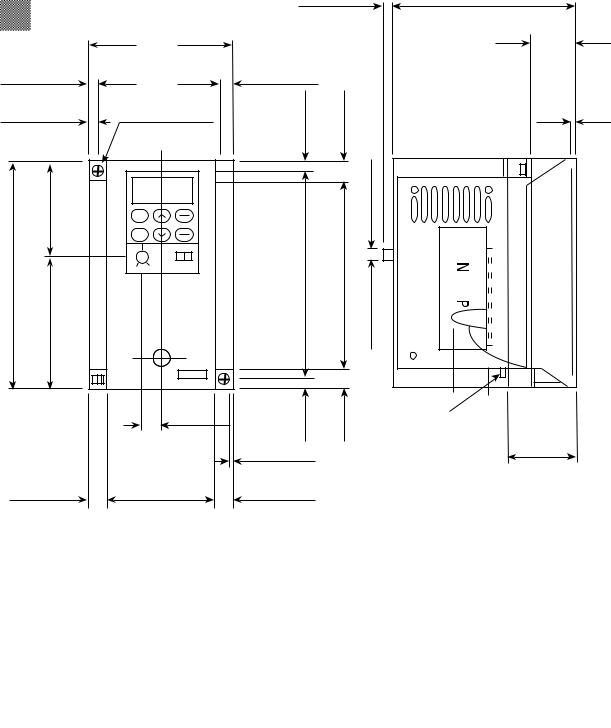
5. External Dimensions
|
|
|
0.24 (6.2) |
D |
|
3.15 (80) |
|
|
D2 |
|
|
|
|
|
0.26 (6.5) |
2.64 (67) |
0.26 (6.5) |
|
|
|
0.20(5) |
0.39(10) |
|
|
.06 (1.5) |
(2 - 5 X 6.2) |
0.06 (1.5) |
||
2 - 0.20 X 0.24 |
|
|
||
1.97 (50) |
|
|
|
0.24 (6.2) |
4.72 (120) |
|
4.33 (110) |
3.94 (100) |
|
2.76 (70) |
|
|
|
|
|
0.43 (11) |
0.20(5) |
(10)0.39 |
TERMINAL M3.5 |
|
|
|
||
|
|
|
|
|
|
|
0.06 (1.5) |
|
D1 |
|
|
|
|
|
0.39 (10) |
2.36 (60) |
0.39 (10) |
|
|
DWG 1: FVRF12C9S-2UX to FVROO1C9S-2UX
|
Rated Current |
|
External Dimensions: inches (mm) |
DWG No. |
|||
Type |
[A] |
|
D |
D1 |
D2 |
|
|
FVRF12C9S-2UX |
0.7 |
|
2.38 (60.5) |
0.89 (22.5) |
0.39 (10) |
|
|
FVRF25C9S-2UX |
1.4 |
|
2.58 (65.5) |
1.08 (27.5) |
0.59 (15) |
DWG 1 |
|
FVRF50C9S-2UX |
2.5 |
|
2.97 (75.5) |
1.48 (37.5) |
0.98 (25) |
|
|
FVR001C9S-2UX |
4.0 |
|
|
3.96 (100.5) |
2.46 (62.5) |
1.97 (50) |
|
|
|
|
|
|
|
|
|
10
FVR-C9S-2UX
0.24 (6.2)
2 - dia. 0.20 (2 - dia. 5)
1.97 (50)
5.12 (130) 3.15 (80)
0.20 (5)
0.45 (11.5)
|
|
0.24 (6.2) |
D |
|
|
|
D2 |
4.33 (110) |
|
|
|
3.86 (98) |
0.24 (6.2) |
|
|
|
|
|
|
|
0.18 (4.5) |
(11.5)0.45 |
0.24 (6.2) |
|
(6)0.24 |
||
|
|
|
|
|
|
|
0.24 (6.2) |
|
4.65 (118) |
4.21 (107) |
|
|
0.24(6.2) |
(11.5)0.45 |
D1 |
|
|
|
TERMINAL M3.5 |
|
0.43 (11) |
|
|
3.43 (87) |
0.45 (11.5) |
|
|
|
|
|
|
DWG 2: FVR002C9S to FVR003C9S-2UX
|
Rated Current |
External Dimensions: inches (mm) |
DWG No. |
||
Type |
[A] |
D |
D1 |
D2 |
|
FVR002C9S-2UX |
7.0 |
5.14 (130.5) |
3.05 (77.5) |
2.56 (65) |
DWG 2 |
FVR003C9S-2UX |
10.0 |
5.53 (140.5) |
3.05 (77.5) |
2.56 (65) |
|
2-'005
11

FVR-C9S-2UX
External Dimensions cont.
0.24 (6.2)
2 - dia. 0.20 (2 - dia. 5)
2.01 (51)
7.09 (180) 5.08 (129)
0.20 (5)
0.45 (11.5)
5.51 (140)
5.04 (128)
0.71 (18)
0.43 (11)
4.61 (117)
|
0.24 (6.2) |
5.45 (138.5) |
|
|
2.58 (65.5) |
2.87 (73) |
|
0.24 (6.2) |
2.09 (53) |
0.49 (12.5) |
|
(6.2)0.24 |
|||
(11.5)0.45 |
0.24 (6.2) |
||
|
|
||
|
0.24 (6.2) |
|
|
5.61 (168) |
5.18 (157) |
|
0.24(6.2) |
(11.5)0.45 |
TERMINAL M4 |
3.37 (85.5) |
|
|
||
|
|
0.47 (12) |
3.78 (96.1) |
0.45 (11.5) |
|
|
|
FVR005C9S-2UX
12
 Loading...