

Page 1

FPD2275W 22-inch Widescreen LCD Monitor
USERGUIDE
®
Page 2

Page 3

Contents
Chapter 1: Using Your Gateway
Flat-Panel Monitor . . . . . . . . . . . . . . . . . . . . . . . . . . . . . . . . . . . . . . . . . . . . . . 1
Connecting the monitor . . . . . . . . . . . . . . . . . . . . . . . . . . . . . . . . . . . . . . . . . . . . . . 2
Attaching the base . . . . . . . . . . . . . . . . . . . . . . . . . . . . . . . . . . . . . . . . . . . . 2
Connecting video inputs . . . . . . . . . . . . . . . . . . . . . . . . . . . . . . . . . . . . . . . . 3
Connecting USB cables . . . . . . . . . . . . . . . . . . . . . . . . . . . . . . . . . . . . . . . . . 5
Connecting power . . . . . . . . . . . . . . . . . . . . . . . . . . . . . . . . . . . . . . . . . . . . . 6
Connecting a security cable . . . . . . . . . . . . . . . . . . . . . . . . . . . . . . . . . . . . . 6
Setting up the optional stand . . . . . . . . . . . . . . . . . . . . . . . . . . . . . . . . . . . . . . . . . . 7
Attaching the USB stand . . . . . . . . . . . . . . . . . . . . . . . . . . . . . . . . . . . . . . . . 7
Adjusting monitor height tension . . . . . . . . . . . . . . . . . . . . . . . . . . . . . . . 10
Adjusting monitor tilt tension . . . . . . . . . . . . . . . . . . . . . . . . . . . . . . . . . . . 11
Connecting the USB hub . . . . . . . . . . . . . . . . . . . . . . . . . . . . . . . . . . . . . . . 12
Setting up the optional speaker bar . . . . . . . . . . . . . . . . . . . . . . . . . . . . . . . . . . . 12
Installing the speaker bar . . . . . . . . . . . . . . . . . . . . . . . . . . . . . . . . . . . . . . 13
Starting the monitor . . . . . . . . . . . . . . . . . . . . . . . . . . . . . . . . . . . . . . . . . . . . . . . . 14
Adjusting monitor settings . . . . . . . . . . . . . . . . . . . . . . . . . . . . . . . . . . . . . . . . . . . 14
Using the EzTouch menu buttons . . . . . . . . . . . . . . . . . . . . . . . . . . . . . . . 14
Using the shortcut menu . . . . . . . . . . . . . . . . . . . . . . . . . . . . . . . . . . . . . . 15
Using the main menu . . . . . . . . . . . . . . . . . . . . . . . . . . . . . . . . . . . . . . . . . 16
Using Picture-in-Picture (PIP) . . . . . . . . . . . . . . . . . . . . . . . . . . . . . . . . . . . 19
Changing Windows screen settings . . . . . . . . . . . . . . . . . . . . . . . . . . . . . . . . . . . . 20
Changing color depth and screen resolution . . . . . . . . . . . . . . . . . . . . . . 20
EzTune software . . . . . . . . . . . . . . . . . . . . . . . . . . . . . . . . . . . . . . . . . . . . . 21
Video modes . . . . . . . . . . . . . . . . . . . . . . . . . . . . . . . . . . . . . . . . . . . . . . . . 22
Power management . . . . . . . . . . . . . . . . . . . . . . . . . . . . . . . . . . . . . . . . . . . . . . . . 23
Energy declaration . . . . . . . . . . . . . . . . . . . . . . . . . . . . . . . . . . . . . . . . . . . 23
Maintaining . . . . . . . . . . . . . . . . . . . . . . . . . . . . . . . . . . . . . . . . . . . . . . . . . . . . . . . 23
Troubleshooting . . . . . . . . . . . . . . . . . . . . . . . . . . . . . . . . . . . . . . . . . . . . . . . . . . . 24
No power . . . . . . . . . . . . . . . . . . . . . . . . . . . . . . . . . . . . . . . . . . . . . . . . . . . 24
No picture . . . . . . . . . . . . . . . . . . . . . . . . . . . . . . . . . . . . . . . . . . . . . . . . . . 24
Display colors are wrong . . . . . . . . . . . . . . . . . . . . . . . . . . . . . . . . . . . . . . 24
Picture has shadows or “ghosts” . . . . . . . . . . . . . . . . . . . . . . . . . . . . . . . . 25
Color is not uniform . . . . . . . . . . . . . . . . . . . . . . . . . . . . . . . . . . . . . . . . . . 25
Image is not sized or centered correctly . . . . . . . . . . . . . . . . . . . . . . . . . . 25
The monitor has pixels that are always dark or too bright . . . . . . . . . . . 25
Speaker bar does not work . . . . . . . . . . . . . . . . . . . . . . . . . . . . . . . . . . . . 25
FAQs . . . . . . . . . . . . . . . . . . . . . . . . . . . . . . . . . . . . . . . . . . . . . . . . . . . . . . . . . . . . . 26
General . . . . . . . . . . . . . . . . . . . . . . . . . . . . . . . . . . . . . . . . . . . . . . . . . . . . . 26
How To . . . . . . . . . . . . . . . . . . . . . . . . . . . . . . . . . . . . . . . . . . . . . . . . . . . . 26
Technical . . . . . . . . . . . . . . . . . . . . . . . . . . . . . . . . . . . . . . . . . . . . . . . . . . . 27
Video/Display . . . . . . . . . . . . . . . . . . . . . . . . . . . . . . . . . . . . . . . . . . . . . . . . 28
Specifications . . . . . . . . . . . . . . . . . . . . . . . . . . . . . . . . . . . . . . . . . . . . . . . . . . . . . . 29
Appendix A: Safety, Regulatory, and Legal Information . . . . . . . . . . . . . . . . . . 31
Recycling . . . . . . . . . . . . . . . . . . . . . . . . . . . . . . . . . . . . . . . . . . . . . . . . . . . 33
i
Page 4

Contents
ii
Page 5

CHAPTER 1
Using Your Gateway
Flat-Panel Monitor
• Connecting the monitor
• Setting up the optional stand
• Setting up the optional speaker bar
• Starting the monitor
• Adjusting monitor settings
• Changing Windows screen settings
• Power management
• Maintaining
• Troubleshooting
• FAQs
• Specifications
1
Page 6
CHAPTER 1: Using Your Gateway Flat-Panel Monitor
Connecting the monitor
To set up the monitor, first attach the base, then make your cable connections.
Attaching the base
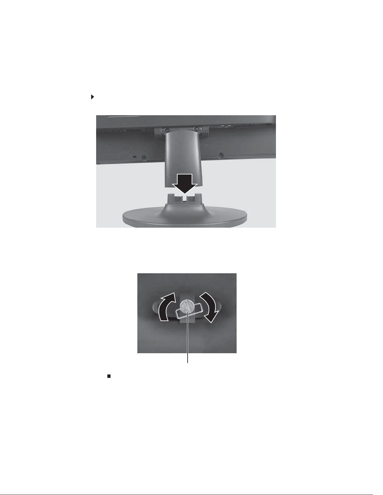
To attach the base:
1 Slide the monitor’s neck onto the base.
2 Place the monitor face-up on a stable surface. A non-slip mat on a tabletop is ideal. Let
the monitor neck hang down over the edge of the table.
3 Slide the neck onto the base.
4 Tighten the thumbscrew with your fingers (or a flat screwdriver) under the base to secure
the neck into place.
Thumbscrew
2
Page 7
Connecting video inputs
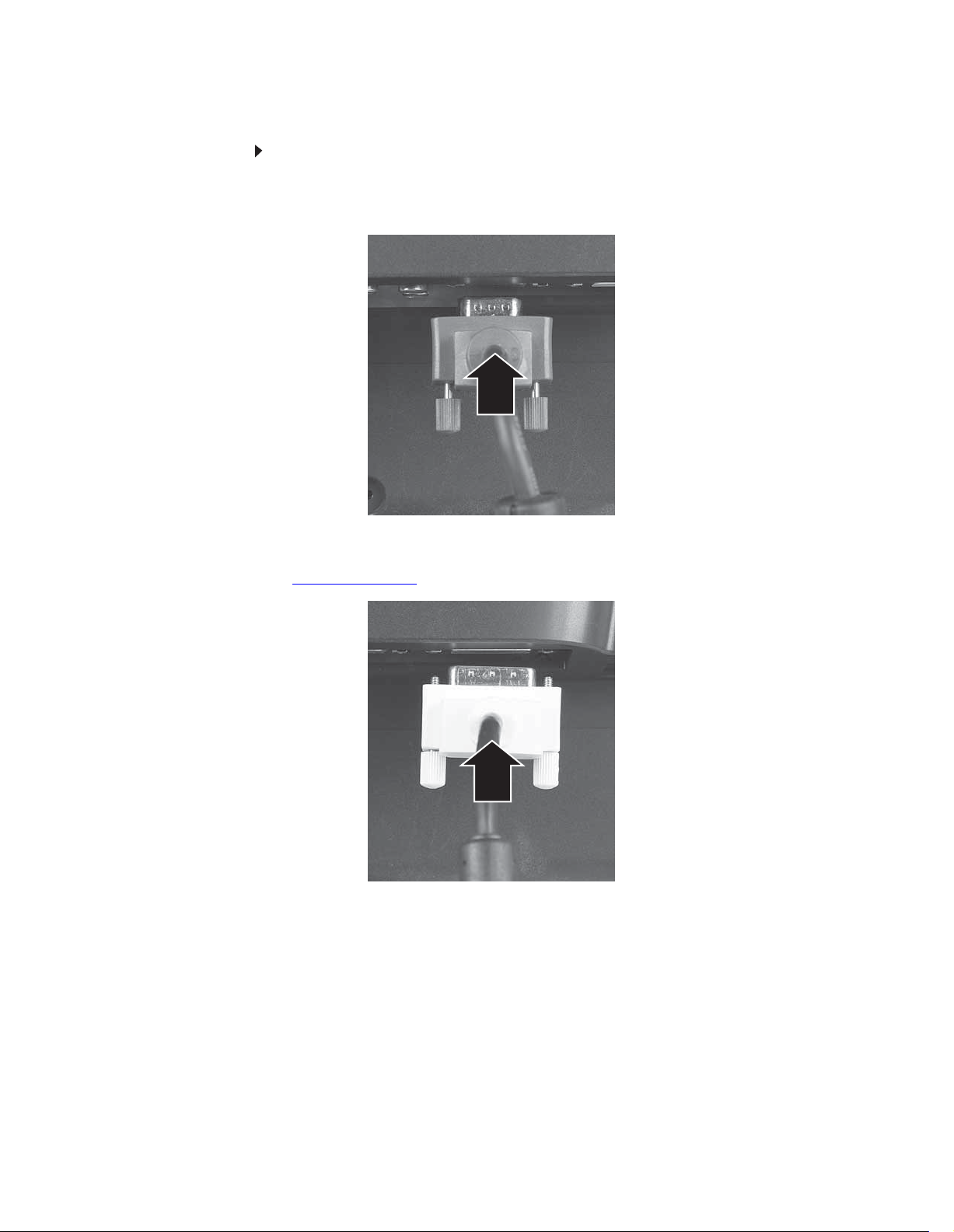
To connect video sources to your monitor:
1 Position your computer and the monitor so you can reach the back of each.
2 Connect the blue VGA video cable to the blue VGA video connector under the back of
the display.
www.gateway.com
- OR -
If your computer has a digital video connector (DVI), connect a DVI video cable (not included)
to the white connector under the back of the display. You can buy a DVI video cable from
www.gateway.com
.
3 Make sure that your computer is turned off, then connect the other end of the video cable
to the matching video port on the back of your computer.
3
Page 8

CHAPTER 1: Using Your Gateway Flat-Panel Monitor
4 Connect other video sources (such as a DVD player, video camera, or receiver) to the
appropriate video jacks on the back of the monitor.
Component red Pr jack
S-Video jack
Composite video in jack Component green Y jack
Component blue Pb jack
• For basic video quality, connect your video device’s composite video in jack to the
corresponding jack on the back of your monitor. (cable not included)
• For better video quality, connect your video device’s S-Video jack to the corresponding
jack on the back of your monitor. (cable not included)
• For best video quality, connect your video device’s component video (green Y,
blue Pb, and red Pr) jacks to the corresponding jacks on the back of your monitor.
(cables not included)
4
Page 9
Connecting USB cables
Your monitor has a built-in, four-port USB 2.0 hub that lets you conveniently connect USB devices.
Because your computer case may be under your desk or inside a cabinet, these monitor-mounted
USB ports can be much easier to access. To use the monitor’s USB ports, you must first connect
the monitor to a USB port on your computer. Because the USB hub uses power from the monitor,
it does not require its own power connection.
To connect USB cables:
Important
The built-in USB 2.0 hub provides only low-speed connections if its USB in
port is connected to a USB 1.1 port on your computer or on a USB hub.
Tip
Use the USB 2.0 ports on the back of the monitor for connecting USB devices
you want to keep connected most of the time, such as a keyboard, a mouse, or
a printer. Use the USB 2.0 ports on the side of the monitor for connecting USB
devices that are frequently disconnected, such as cameras, flash drives, and USB
hard drives.
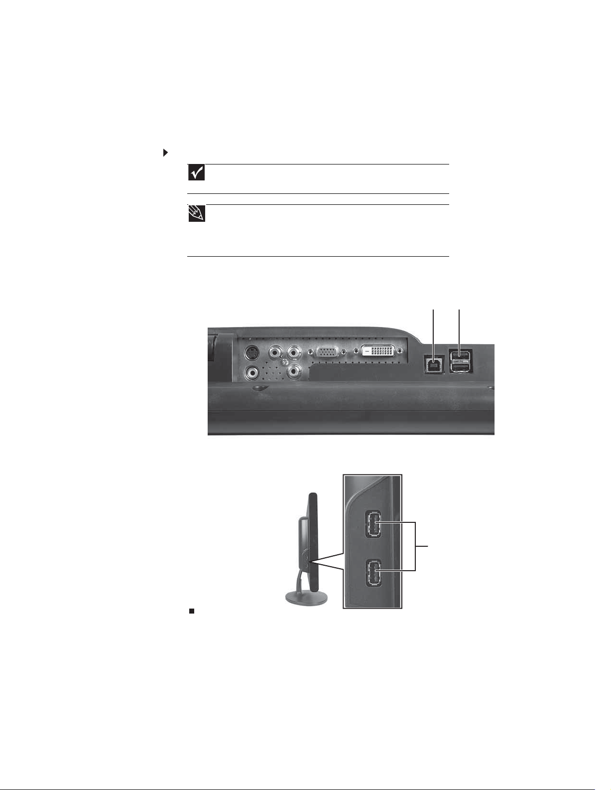
1 Connect the included USB cable to the USB in (“B” type) port on the back of your monitor,
then connect the other end of the cable to a USB 2.0 port on your computer.
www.gateway.com
USB in (“B” type) port USB ports
2 Connect any USB device to one of the available USB 2.0 ports on the left side or back of
the monitor.
USB ports
5
Page 10
Connecting power
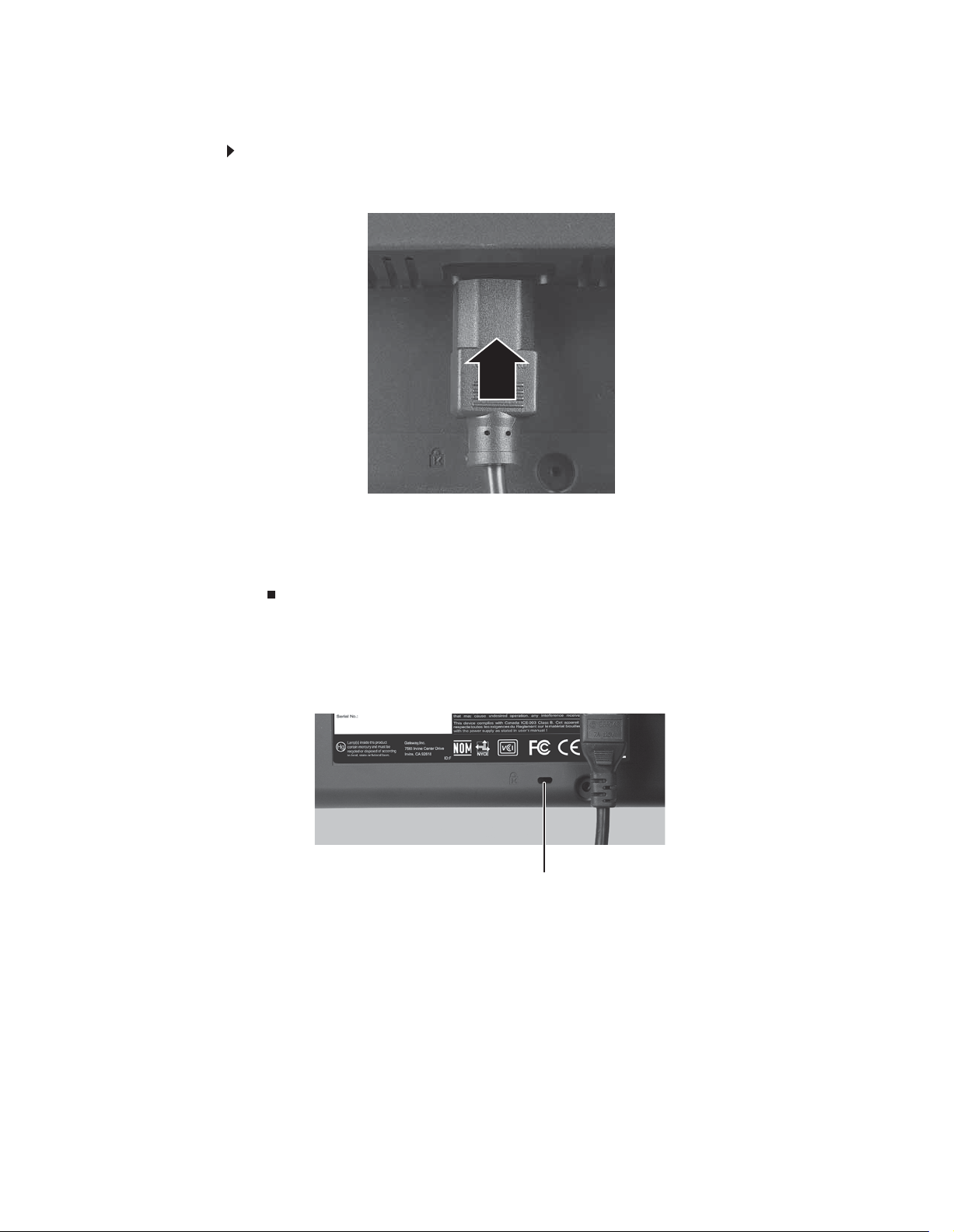
To connect power:
1 Position your monitor so you can reach the back, then connect the power cord to the power
2 Plug the power cord into a correctly grounded power outlet. We recommend using a surge
3 To make sure that the monitor’s power is correctly connected, check the power button
CHAPTER 1: Using Your Gateway Flat-Panel Monitor
connector under the back of the monitor.
protector to protect your monitor from voltage spikes.
on the front button panel. The power icon on the power button should be glowing purple.
If the power icon is not visible, power is not connected.
Connecting a security cable
You can secure your monitor to your computer desk (or to another heavy object) with a cable
lock. To connect a cable lock, follow the cable lock’s instructions to connect it to the Kensington
lock slot on the back of your monitor (cable lock not included).
Kensington lock slot
6
Page 11
www.gateway.com
Setting up the optional stand
Attaching the USB stand
In the United States, you can buy an adjustable USB stand from www.gateway.com. The stand
can be adjusted for height, tilt, and screen rotation. With EzTune software installed on your
computer, a sensor inside your monitor detects the rotation mode (portrait or landscape) your
monitor is in, and rotates the screen image accordingly.
When the stand is connected to your computer’s USB port, you can connect up to four USB devices
to the USB 2.0 ports on the stand. Including the ports on your monitor, you could have a total
of eight easy-to-access USB ports on your monitor and stand together.
To attach the adjustable stand:
1 Make sure that the monitor is turned off.
2 Place the monitor face-up on a stable surface. A non-slip mat on a tabletop is ideal. Let
the monitor base hang down over the edge of the table.
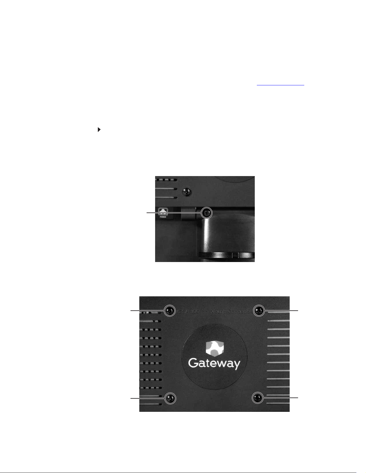
3 Remove the two screws from the neck hinge, then remove the neck from the LCD panel.
Do not discard the screws.
Screw
4 Place the hinge cover over the hinge, then attach the hinge cover using the screws you
removed from the original neck hinge. The hinge cover came with your monitor.
5 Remove the four small screws from the back of the LCD panel. Do not discard the four
screws.
Screw Screw
Screw
Screw
7
Page 12

CHAPTER 1: Using Your Gateway Flat-Panel Monitor
6 Slide the adjustable stand’s neck onto the base.
7 Tighten the thumbscrew with your fingers (or a flat screwdriver) under the base to secure
the neck into place.
Thumbscrew
8 With the stand facing you, press the mounting bracket lever to the left and hold it, then
remove the bracket from the stand.
8
Page 13

www.gateway.com
9 Attach the bracket to the LCD panel using the four screws you removed previously.
Screws
Screws
10 Slide the neck’s bracket slot onto the bracket’s mounting tab.
11 Press the bracket lever to the right and hold it, then lower the neck into place and release
the lever.
9
Page 14

CHAPTER 1: Using Your Gateway Flat-Panel Monitor
Adjusting monitor height tension
The stand is factory adjusted to maintain the height for your monitor. However, if it does not
stay in place when you let go, you need to change the stand’s height tension. You also need to
adjust the stand if the amounts of force required to raise and lower the monitor are not equal.
To adjust your monitor’s height tension:
1 Press the screwdriver access hole cap from below the base to remove it from the base.
Screwdriver access cap
2 Insert a Phillips screwdriver through the access hole in the base and onto the height tension
screw (on the back of the stand, in the slot above the USB In port).
Height tension screw
3 Adjust the height tension screw so the monitor stays in place when you let go. If the monitor
lowers by itself when you let go, turn the screw clockwise several complete turns. If the
monitor rises when you let go, turn the screw counter-clockwise several complete turns.
You may need to turn the screw several times before the tension is correct for your size
of monitor.
4 Adjust the height tension screw so the raising and lowering forces are equal. After the
forces are equalized, turn the tension screw clockwise two to four turns to slightly decrease
the lifting tension.
5 For optimum viewing, adjust the height so the top of the monitor is about 1 inch (2.5 cm)
below eye level.
10
Page 15

Adjusting monitor tilt tension
To adjust your monitor’s tilt tension:
• Adjust the tilt tension screw (on the top of the stand) so the monitor stays in place when
you let go. If the monitor changes its tilt angle when you let go, turn the screw clockwise
one complete turn to increase the tension.
www.gateway.com
Tilt tension screw
Ergonomic guidelines
The recommended screen positioning is based upon the following guildelines. These guidelines
are based on available scientific literature and published standards.
Screen height
The recommended screen height for displays (except in special circumstances, such as for bifocal
use) is that the top of the display should be set at or slightly below (about 1 inch or 25 mm)
your eye level while you are sitting in a comfortable working posture. This guideline places the
center of the screen at an ideal 15° to 20° viewing angle for most desktop displays. If the display
has multiple users, the screen height should be easily adjustable to accommodate each user’s
height and preference.
Screen tilt
The screen should be tilted so your line of sight is perpendicular to the screen. This angle creates
the most consistent viewing distance when scanning from the top of the screen to the bottom.
You may need to adjust lighting to avoid screen glare when the screen is tilted upward.
Screen distance from user
The screen should first be placed at arm’s length from the user, then adjusted back and forth
to suit individual preference.
11
Page 16

CHAPTER 1: Using Your Gateway Flat-Panel Monitor
Connecting the USB hub
The optional USB stand has a built-in, 4-port, USB 2.0 hub. To use these USB connectors, you
need to connect the hub to power and to your computer.
To connect your USB stand’s built-in USB hub:
1 Plug the included USB cable into the USB In port on the back of your USB stand and into
a USB 2.0 port on your computer. If you connect the stand to a USB 1.1 port on your
computer, the stand’s USB hub operates in USB 1.1 mode.
USB In port
Power connector USB 2.0 ports
2 To provide full power to your stand’s USB ports, connect the AC power adapter to the power
connector on the back of your USB stand and into an AC power outlet.
Setting up the optional speaker bar
Power/Volume control
Power indicator
Headphone jack
Microphone jack Headphone jack
Kensington lock slot
12
Bass port Bass port
Page 17

Installing the speaker bar
To install the speaker bar:
Tip
When using the speaker bar with a DVI connection, we recommend that you
use the right-angle DVI cable so the speaker bar does not obstruct the cable.
1 Tilt the screen back, then center the speaker bar below the screen. Make sure that the
speakers face forward.
2 Tighten the two thumbscrews on the back of the speaker bar.
www.gateway.com
3 Connect the speaker bar’s USB power cord to any available USB port on your computer.
4 Connect the speaker bar’s headphone (green) and microphone (pink) cables to your
computer’s headphone and microphone jacks.
5 If it is not already on, turn on your computer.
6 Turn on the speaker bar by rotating the power/volume knob clockwise.
13
Page 18

CHAPTER 1: Using Your Gateway Flat-Panel Monitor
Starting the monitor
To start the monitor:
1 Press the power button on the front of monitor. The power LED on the power button
changes from purple (off) to blue (on).
2 Turn on your computer. After your computer is running, the power LED on the monitor’s
power button should be blue. Allow about 10 seconds for the display image to appear. If
the power LED is not blue or you do not see a display image, check the connections. For
more troubleshooting information, see “Troubleshooting” on page 24.
3 Adjust the tilt of the monitor for the best viewing angle.
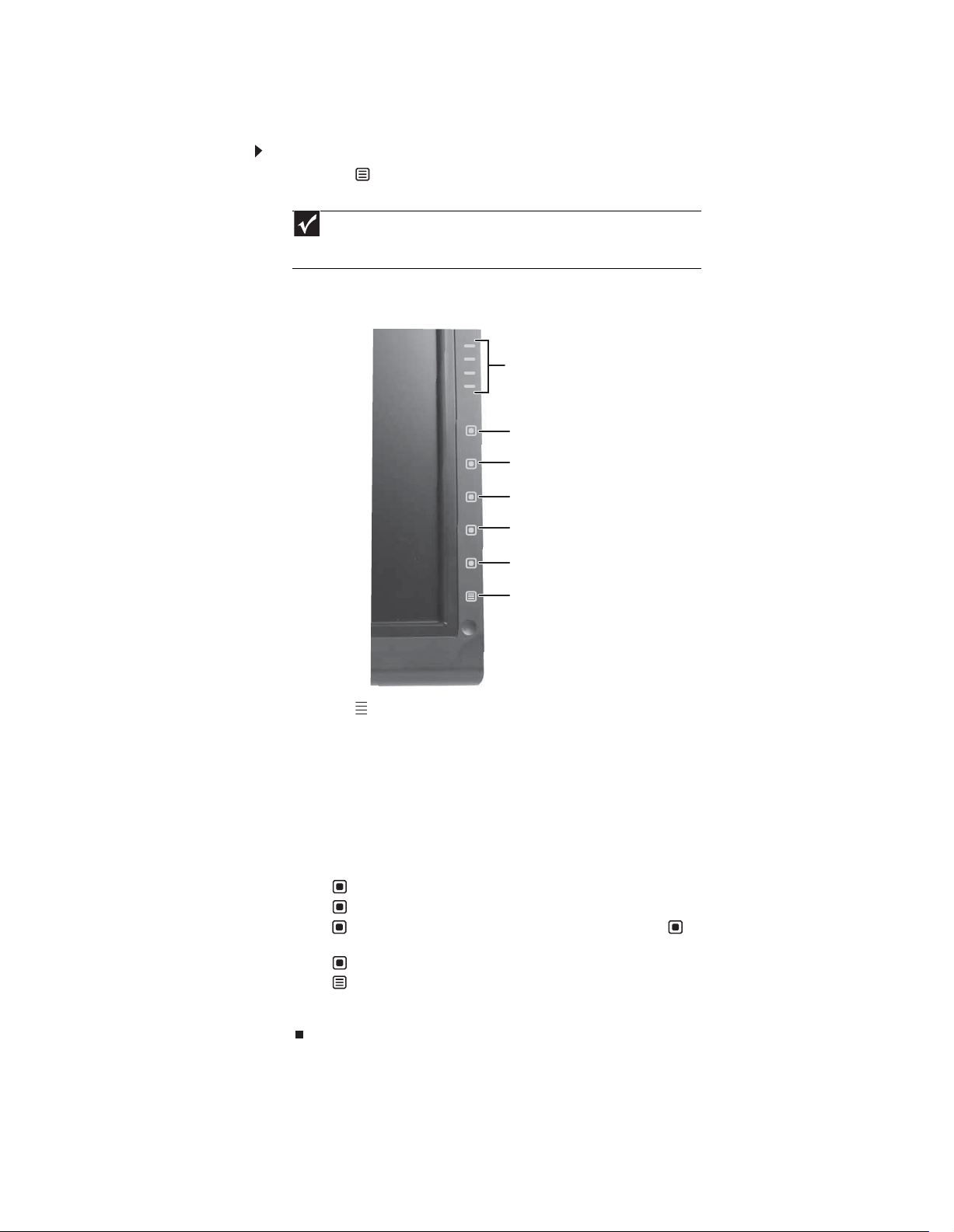
4 After you see the Windows desktop, press the (Menu) button on the front of your
monitor, then press (Auto) to automatically adjust your display image to the ideal
settings.
5 To mute the volume of the sounds accompanying button presses, press the (Menu)
button on the front of your monitor, press (Main Menu), press (Advanced), press
(Audio Feedback), then press the lower (Adjust) buttons until the volume bar is at
the bottom of the scale.
6 Use the on-screen display (OSD) to adjust other monitor settings. For more information,
see “Adjusting monitor settings” on page 14.
Adjusting monitor settings
Use the monitor controls (located on the monitor itself) and computer controls (accessible through
Windows) to adjust the display image. For more information about computer controls, see
“Changing Windows screen settings” on page 20.
Using the EzTouch menu buttons
This monitor features an on-screen display (OSD) and EzTouch menu buttons that let you adjust
contrast, brightness, and other settings for the monitor. The monitor saves changes you make
to the settings, even if you turn off the monitor.
Your monitor has two levels of menus, and the functionality of the touch buttons depends on
the menu that is currently open:
• The shortcut menu lets you quickly change some of the most commonly accessed settings.
• The main menu lets you precisely adjust all levels of settings.
14
Page 19
Using the shortcut menu
To use the shortcut menu:
1 Press the (Menu) button on the front of your monitor. The rest of the button icons light
up and the shortcut menu opens.
Important
The buttons are very sensitive, and may be “pressed” by holding your finger
just above its surface. To completely “release” a touch button, make sure that you
lift your finger well away from the button.
2 To use an EzTouch menu button, lightly touch its icon. For adjusting a setting’s values, you
can press and hold touch buttons as you would conventional buttons.
www.gateway.com
Theme Select
Input Select
Auto
PIP On
PIP Settings
Cancel
Main Menu
• Press the (Theme Select) buttons to cycle through the preset video themes (brightness,
contrast, and temperature configurations):
• User
• Movie
• Game
• Picture
• Web
• Warm
• Cool
• Press (Input Select) to cycle through the available video sources.
• Press (Auto) to automatically adjust your display image to the ideal settings.
• Press (PIP On) to turn on Picture-in-Picture, and press (PIP Settings) to adjust the
PIP position, size, and other advanced PIP settings.
• Press (Cancel) to exit the shortcut menu.
• Press (Main Menu) to open the main menu.
• To turn off the button icons and close the menu, wait about ten seconds without pressing
a button.
15
Page 20

Using the main menu
To use the main menu:
1 Press the (Menu) button on the front of your monitor. The rest of the button icons light
up and the shortcut menu opens.
holding your finger just above its surface. To completely “release” a touch button,
make sure that you lift your finger well away from the button.
2 To use a button, lightly touch its icon. For adjusting a setting’s values, you can press and
hold touch buttons as you would conventional buttons.
3 Press (Main Menu). The main menu opens.
CHAPTER 1: Using Your Gateway Flat-Panel Monitor
Important
The EzTouch menu buttons are very sensitive, and may be “pressed” by
Choose option or mode, Adjust
setting
Select
Back
Menu or Menu Off
Tip
While the OSD is active, on-screen labels appear next to the buttons to help
you identify them.
4 Press the (Choose Option) buttons to highlight a setting, then press (Select) to open
the selected menu or setting.
5 Press the (Adjust) buttons to adjust the setting or change the option.
6 Press (Back) to return to a previous menu.
7 When you have finished making all adjustments, press (Menu Off) to exit.
16
Page 21

OSD Menu Description
www.gateway.com
Main menu
Picture menu
PIP Settings menu
Auto—Automatically adjusts your monitor to its optimum settings. (VGA input only)
Picture—Opens the Picture menu, where you can adjust brightness, contrast, and gamma.
PIP—Opens the PIP Settings menu, where you can adjust the source, position, size, and
transparency of the Picture-in-Picture image.
Video adjust—Opens the Video Adjust menu, where you can adjust the RGB (red, green, and blue)
values of the video image from a source such as composite video, S-Video, or component video.
Geometry—Opens the Geometry menu, where you can adjust image size and minimize distortions.
(VGA input only)
Advanced—Opens the Advanced menu, where you can adjust color balance, change the OSD
language, and display information about current monitor settings.
Reset—Resets the monitor to its factory settings for the currently displayed input.
Brightness—Adjusts the amount of light in the darkest portion of the picture. Use the lowest
brightness setting you are comfortable with to maximize the life of the monitor backlights. You may need
to readjust brightness after the monitor warms up.
Contrast—Adjusts the level of white between the lightest and darkest portions of an image.
Gamma—Customizes the gamma level. High gamma levels increase white levels and low gamma
levels increase contrast.
PIP Display—Toggles the display of the PIP window.
Source—Sets the source of the video used in the PIP window.
Position—Sets the position of the PIP window on the main screen.
Size—Sets the size of the PIP window.
Transparency—Sets the transparency of the PIP window. The PIP window can be from almost
transparent to completely opaque. When the PIP window is transparent, you are able to see through
the PIP video display to your Windows desktop, which makes it easier to access your computer programs
while watching video.
Swap—Switches the PIP image to the main image, and the main image to the PIP image.
PIP Picture—Opens a menu where you can set the PIP brightness, contrast, saturation, and
tint/hue.
17
Page 22

OSD Menu Description
CHAPTER 1: Using Your Gateway Flat-Panel Monitor
Video Adjust menu
Unless otherwise indicated, these settings apply only to SD (standard definition) video at 480i and below.
Where “PC input” is indicated, the resolutions that apply are from 800 × 600 to 1680 × 1050.
Sharpness—Adjusts sharpness for video images.
Video Scaling—Sets video aspect ratios and scaling between Wide, Zoom, 1:1, and Panoramic
modes. PC input: sets resolution aspect ratios and scaling between Wide, Zoom, and 1:1.
Wide mode stretches a standard broadcast or full-frame image to fill the
entire screen. Widescreen (1.76:1) images fill the entire screen without
distortion, while widescreen (1.85:1 and 2.35:1) images appear without
distortion but with black bars at the top and bottom. PC input: Stretches the
image to fit the entire screen.
Zoom mode crops off a portion of a widescreen image in order to fill
the entire screen with a distortion-free and black bar-free image. PC input:
Zooms the image to fill the screen from top to bottom with black bars on the
left and right sides of the image.
1:1 mode preserves the movie’s original aspect ratio, so a standard broadcast
or full-frame movie appears with black bars on the left and right of the image.
PC input: Preserves the original aspect ratio of the resolution by using black bars
on the left and right sides and variable sizes of black bars on the top and bottom
of the image (depends on resolution).
Panoramic mode uses selective distortion to stretch a standard broadcast
or full-frame image to fill the entire screen. Unlike Wide mode, Panoramic
mode stretches only the left and right sides of the image, and leaves the center
of the image distortion free.
Noise Reduction—Uses noise reduction filters that adapt to the amount
of noise and motion from the video source.
Film Mode Detection—Film Mode Detection detects frame rates of the source image and adapts
the frame rate of the display for ultimate image quality. Bad Edit Detection and Correction corrects
incorrectly synchronized video.
Auto Video Enhance—Enables DCDi, Cross Color Reduction, and MADI for optimized video
performance.
DCDi by Faroudja—Directional Correlation De-interlacing reduces jagged edge artifacts on diagonal lines.
Cross Color Reduction—Reduces cross-color artifacts, such as unintentional flashing colors or rainbow
patterns, that result from composite video signals.
MADI—Motion-Adaptive De-Interlacing ensures a more static (flicker-free) display image for image
sections not containing moving elements, and ensures smoother edges for moving elements.
18
Page 23

OSD Menu Description
www.gateway.com
Geometry menu
Advanced menu
H Position—Moves the display image left and right. You can also press the Auto button to configure
the vertical and horizontal position automatically.
V Position—Moves the display image up and down. You can also press the Auto b utto n t o c onf ig ure
the vertical and horizontal position automatically.
Clock—Minimizes any vertical bars or stripes visible on the screen background. The horizontal
screen size will also change.
Phase—Minimizes any horizontal distortion and clears or sharpens the displayed characters.
Color—Customizes the color levels.
Language—Changes the language of the OSD.
LED Mode—Changes the brightness of the Standby and Power LED to Day Mode or Nite Mode.
When watching movies in a darkened room, you may want to change the LED mode to Nite Mode to
avoid an over-bright, distracting power LED indicator.
DVI Video mode—Changes the DVI video mode by enabling either RGB Color Space (used for
digital input) and YUV Color Space (used for analog TV input such as NTSC, PAL, and SECAM).
Audio Feedback—Changes the volume of the sounds that accompany button presses. Decrease
all the way down to completely mute the button tones.
Information—Displays current screen resolution and input source for the main display.
Resolution reminder—If the computer display input (VGA and DVI) is not set to 1680 × 1050,
displays a reminder that you should change your computer’s settings to use the optimum 1680 × 1050
resolution. If you prefer using your monitor at a resolution less than 1680 × 1050, use this option to turn
off the Resolution Reminder. For information on changing your computer’s display resolution, see
“Changing Windows screen settings” on page 20.
Reset All—Resets all values to the factory settings.
Using Picture-in-Picture (PIP)
Picture-in-Picture (PIP) is a convenient way to view video from multiple video sources at the same
time. Refer to the following chart to determine which combinations of video sources can be used
as a PIP display.
PIP display
Main display
VGA - OK OK* OK OK
DVI OK - OK OK OK
Component (Y Pb Pr) No OK - OK OK
S-Video OK OK OK - No
Composite OK OK OK No -
* Only 480i component (Y Pb Pr) video can be use d with VGA as a PIP. With this combination, the Swap feature is not available. To switch to full-screen component video when 480i content is
used as a PIP, press the Input button on the side of the monitor.
If a 480p source is input to the Y Pb Pr jacks and Y Pb Pr is a PIP display within a VGA main display, then the PIP image will be distorted. Change the output of your external Y P b Pr device to 480i
if PIP is required with VGA to eliminate the PIP distortion. For more information, see your Y P b Pr device’s user guide.
** For some video resolutions, refresh rates, and video scaling modes, PIP may not be allowed. If you receive a message that PIP is not available, try the following:
■
Adjust the refresh rate in Windows to 60 Hz. See Windows online Help for more information.
■
Adjust the video scaling mode to Wide on the monitor.
■
Change the resolution of the Windows desktop to match the monitor’s full resolution of 1680 × 1050. For more information see “Changing color depth and screen resolution” on page 20.
VGA** DVI** Component (Y Pb Pr) S-Video Composite
19
Page 24
CHAPTER 1: Using Your Gateway Flat-Panel Monitor
Changing Windows screen settings
Adjusting the color depth and screen area are two of the most basic display settings you may
need to change. You can also adjust settings such as the screen background and screen saver.
Changing color depth and screen resolution
Color depth and screen resolution are two of the most basic monitor settings you may need to
change to suit your needs.
Color depth is the number of colors your computer uses to display images on your monitor. Most
images look best displayed with the maximum number of colors available. If the color in your
images seems “false” or “jumpy,” especially after you have played a game or run a video-intensive
program, check the color depth setting and return it to the highest color setting, if necessary.
Screen resolution is the number of pixels (individual colored dots) your computer uses to display
images on your monitor. The higher the resolution, the more information and screen components
(such as icons and menu bars) can be displayed on the monitor.
Help
For more information about adjusting the screen, click Start, then click Help and
Support. Type adjusting monitor settings in the Search Help box, then press E
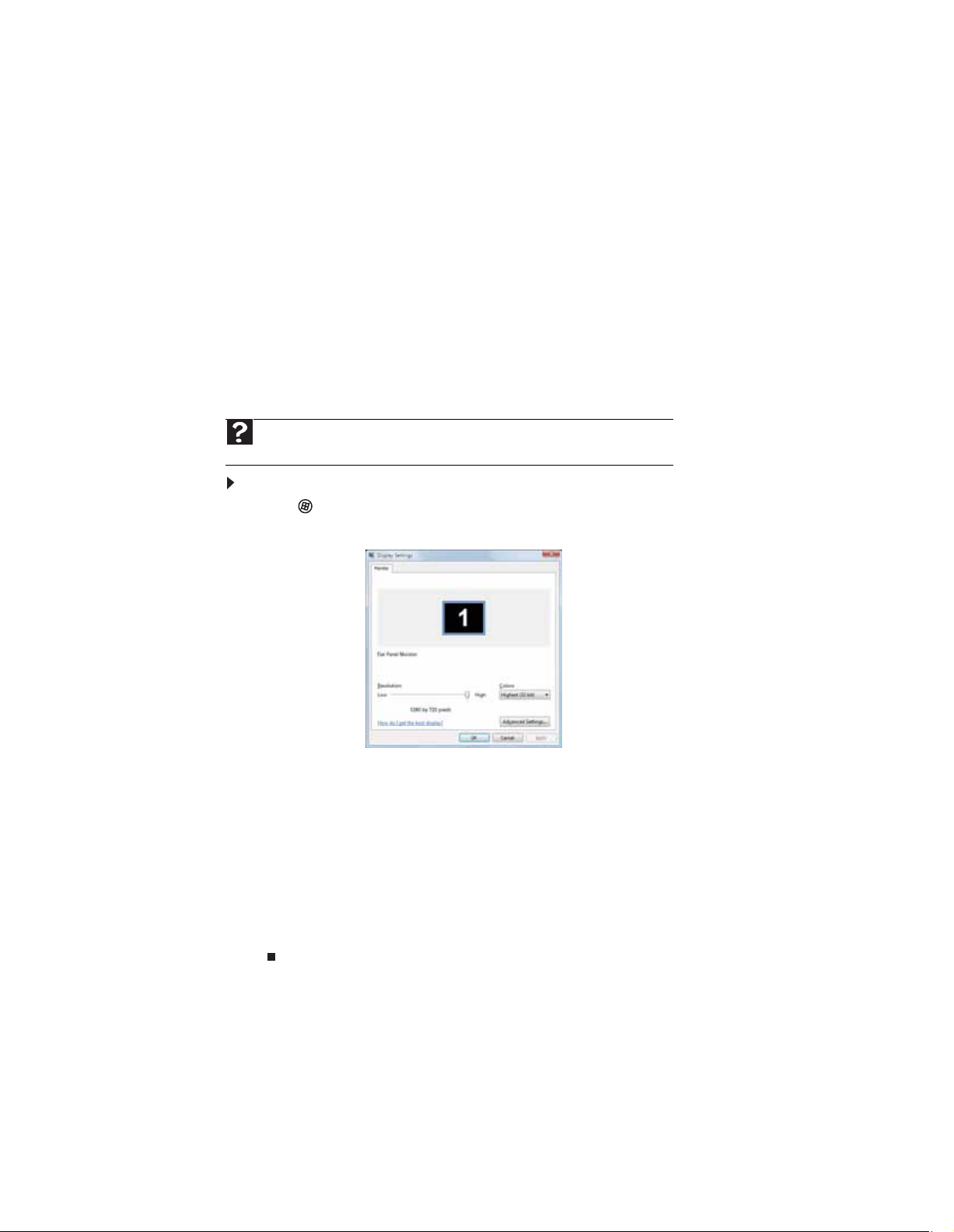
To change the color depth or screen resolution:
1 Click (Start), Control Panel, then under Appearance and Personalization, click Adjust
Screen Resolution. The Display Settings dialog box opens.
NTER.
20
2 To change the color depth, click the Colors list, then click the color depth you want.
• Low (8-bit) = 256 colors
• Medium (16-bit) = 65,500 colors
• Highest (32-bit) = 16,700,000 colors
3 To change the screen resolution, drag the Resolution slider to the size you prefer.
4 Click Apply. If the new settings do not look right, click No. If the new settings make the
screen illegible and you cannot click No, the settings return to their previous values after
several seconds.
5 Click OK, then click Yes to save your changes.
Page 25
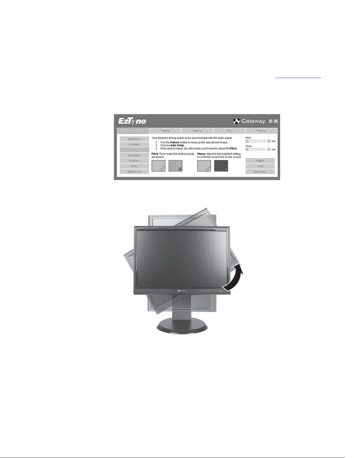
EzTune software
When installed onto your computer, EzTune™ software lets you control many of the monitor
settings from your computer. With EzTune, you can:
• Change the orientation of the image (landscape to portrait) by just rotating the screen
• Change brightness, contrast, and color balance
• Change screen geometry
• Set the display position and resolution
For more information, see the program’s CD or the installed program’s online help.
www.gateway.com
(requires the optional height-adjustable stand available in the U.S. at www.gateway.com
)
Using landscape and portrait modes (requires optional height-adjustable stand)
EzTune automatically switches the display to the appropriate mode (landscape or portrait) when
you rotate the screen. This feature works only with VGA or DVI input (the OSD itself does not
rotate into portrait mode).
While using portrait mode:
• Full-screen video may display incorrectly or be slow.
• Video games or other full-screen applications may not be fully compatible.
• Some programs are not able to recognize and adapt to your monitor’s portrait mode. If
you experience problems with a program while using portrait mode, switch to landscape
mode and restart the program.
21
Page 26

Video modes
CHAPTER 1: Using Your Gateway Flat-Panel Monitor
Your monitor supports several video modes. If you do not use the best mode for the monitor,
the display image may look slightly “fuzzy.”
Mode Resolution Horizontal
frequency (kHz)
1 720 × 400 31.469 70 N
2 640 × 480 31.469 60 Y
3 640 × 480 37.9 72 N
4 640 × 480 37.5 75 N
5 800 × 600 35.1 56 N
6 800 × 600 37.879 60 Y
7 800 × 600 48.1 72 N
8 800 × 600 46.875 75 N
9 1024 × 768 48.363 60 Y
10 1024 × 768 56.5 70 N
11 1024 × 768 60.123 75 N
12 1152 × 864 67.5 75 N
13 1280 × 1024 64 60 Y
14 1280 × 1024 80 75 N
Vertical
frequency (Hz)
Available in DVI
mode
15 1400 × 1050 65.317 60 Y
16 1400 × 1050 82.278 75 N
17 1440 × 900 55.935 60 Y
18 1440 × 900 70.635 75 N
19 1680 × 1050 65.29 60 Y
20 1680 × 1050 74.9 75 N
22
Page 27

Power management
Energy declaration
When connected to a computer that supports the VESA Display Power Management Signaling
(DPMS) Protocol, the monitor can conserve significant energy by reducing power consumption
during periods of non-use. When your computer goes into the energy saving mode, the monitor
will then enter the Active Off mode (sleep). In the Active Off mode the Power LED will still show
orange.
Use these conventions and the power can be reduced to the following levels:
VESA State LED Indicator Power Consumption
On Blue <75 W
Standby Orange <5 W
Off Purple ≤ 2W
To “wake” the monitor when it is in Standby/Active Off mode, move the mouse or press any
keyboard key.
You can change the monitor’s power management settings using the Windows Control Panel.
To access the monitor’s power management options:
1 Click Start, then click Control Panel. The Control Panel window opens. If your Control Panel
is in Category View, click Performance and Maintenance.
2 Click/Double-click Power Options. The Power Options Properties dialog box opens.
3 Click Turn off monitor to open the list of values for this setting, then click the amount
of time you want to wait for the monitor to change to Standby mode.
4 Click OK. Your settings are saved, and the dialog box closes.
www.gateway.com
Maintaining
To keep the monitor in optimal working order:
• Do not block the ventilation holes.
• Do not expose the monitor to rain or use near water.
• Keep the monitor away from radiators or heat vents.
• Keep the monitor out of direct sunlight.
• To clean the monitor, use a soft cloth slightly moistened with water only. Wipe the cabinet,
Caution
Do not use any type of abrasive pad or glass cleaner. You will permanently
scratch the screen.
screen, and controls.
23
Page 28

CHAPTER 1: Using Your Gateway Flat-Panel Monitor
Troubleshooting
Important
Make sure that the monitor has warmed up for approximately 30 minutes before
making any judgments about the picture quality.
If you have problems with the monitor, the information in this troubleshooting section may help
you solve them.
No power
Make sure that the power cord is connected correctly to both the back of the monitor and the
wall outlet. For more information about connecting the power cord, see “Connecting the monitor”
on page 2.
No picture
• Press (Menu), then (Input Select) to make sure that you have selected the correct
video source.
• Make sure that the power cord is connected correctly to both the back of the monitor and
the wall outlet. For more information about connecting the power cord, see “Connecting
the monitor” on page 2.
• Make sure that the video cable is connected securely to the back of the monitor and
computer. For more information about connecting the video cable, see “Connecting the
monitor” on page 2.
• Make sure that the monitor is turned on.
• If the power LED is orange:
• Make sure that your computer is turned on.
• Move the mouse or press any key on the keyboard to bring the monitor out of sleep
mode.
• Restart your computer with the monitor turned on.
• Make sure that the video cable is not damaged.
• Check the end of the video cable for any pins that might be bent or pushed in.
• Turn off the monitor and unplug the video cable from the back of your computer. Turn
the monitor back on and wait for ten seconds. If the monitor is functioning correctly, a
“No Signal” message appears. For more information about connecting the video cable, see
“Connecting the monitor” on page 2.
Display colors are wrong
• Press (Menu), then (Auto) to automatically adjust the display image to the
ideal settings.
• Restart your computer with the monitor turned on.
• Make sure that the video cable is connected securely to the back of the monitor and your
computer. For more information about connecting the video cable, see “Connecting the
monitor” on page 2.
• Make sure that the video cable is not damaged.
• Check the end of the video cable for any pins that might be bent or pushed in.
24
Page 29

www.gateway.com
Picture has shadows or “ghosts”
• Press (Menu), then (Auto) to automatically adjust the display image to the
ideal settings.
• Remove any extension cables or switchboxes.
• Make sure that the video cable is connected securely to the back of the monitor and your
computer. For more information about connecting the video cable, see “Connecting the
monitor” on page 2.
• Make sure that the video cable is not damaged.
• Check the end of the video cable for any pins that might be bent or pushed in.
• Make sure that your monitor connection is using the VGA cable that came with your
monitor.
Color is not uniform
• Press (Menu), then (Auto) to automatically adjust the display image to the
ideal settings.
• Make sure that the monitor warms up for at least 30 minutes before making a final
judgment about color uniformity or brightness.
Image is not sized or centered correctly
• Press (Menu), then (Auto) to automatically adjust the display image to the
ideal settings.
• Use the position controls to adjust the image. For instructions on how to adjust the display
image position, see “Adjusting monitor settings” on page 14.
The monitor has pixels that are always dark or too bright
• This condition is normal and inherent in the TFT technology used in active-matrix LCD
screens. Gateway’s inspection standards keep these to a minimum. If you feel these pixels
are unacceptably numerous or dense on your display, contact Gateway Customer Care to
identify whether a repair or replacement is justified based on the number of pixels affected.
Speaker bar does not work
I installed the speaker bar, but no sound is coming out of the speakers.
• Make sure that the speaker bar power cord is plugged into a USB port on the back of your
computer.
• Make sure that the volume control knob on the front of the speaker bar is turned on. Turn
the knob clockwise to turn on the speakers and increase the volume. Turn the knob
counter-clockwise to decrease the volume and turn off the speakers. The speaker bar’s
power indicator lights blue when power is connected and the speakers are turned on.
I checked all the connections and the speaker volume control is on, but I still do not get any
sound.
• Your headphone/speaker jack may have been muted using Windows sound controls. To
check your headphone/speaker mute settings, click the speaker icon in the Windows
taskbar, or click Start, Control Panel, Sounds and Audio Devices, the Volume tab, then
click Advanced. For optimum volume control using the speaker bar, we recommend that
you set the Windows volume mid-way between the lowest and highest setting.
I want to plug in my headphones, but there is a headphone jack on both sides of the speaker
bar. Which should I use?
• You can use either jack or both jacks at the same time.
25
Page 30

FAQs
CHAPTER 1: Using Your Gateway Flat-Panel Monitor
The sound coming from the speakers sounds distorted.
• Turn down the volume until the distortion disappears.
• Check the audio output volume of the sound device the speaker bar is connected to. If
the audio device’s output volume is set too high, the speaker bar’s sound may always be
distorted. To adjust the audio device’s output volume, see the device’s user guide. To adjust
the volume in Windows XP, click the speaker icon in the Windows taskbar, or click Start,
Control Panel, Sounds and Audio Devices, the Volume tab, then click Advanced. For
optimum volume control using the speaker bar, we recommend that you set the Windows
volume mid-way between the lowest and highest setting.
I plugged my microphone into the speaker bar’s microphone jack, but my computer cannot
record any sound.
• Make sure that the speaker bar’s pink microphone plug is connected to the microphone
jack on your computer.
• Your microphone jack may have been muted using Windows sound controls. To check your
microphone’s mute settings, click the speaker icon in the Windows taskbar, or click Start,
Control Panel, Sounds and Audio Devices, the Volume tab, then click Advanced.
This section contains answers to frequently asked questions.
General
How To
What is DCDi® by Faroudja?
DCDi® by Faroudja is a video mode algorithm that stands for Directional Correlation
De-Interlacing. It was initially designed for fast-action video-based material. Its general purpose
is to reduce jagged edges along diagonal lines caused by interpolation. Utilizing this algorithm,
DCDi does not simply weave together two fields of video that match. DCDi creates new
information through interpolation which “smooths” the diagonal edges. DCDi constantly monitors
edge transitions and fills in any of the gaps that need smoothing.
I have the monitor connected to my notebook’s VGA port and I see no image on the screen.
You have two options:
• If your notebook supports dual displays, you can use both your notebook’s display
and this monitor in extended desktop multi-monitor mode. See Windows Help to learn
how to enable multiple monitors.
• You can also use this monitor as your primary monitor and not use the notebook’s
screen. Notebook computers typically have an FN key combination that lets you toggle
between your notebook’s display and an externally attached display. On Gateway
notebooks, this key combination is F
keys. See your notebook user guide for more information.
N+F4. The F4 key is located along the top row of
Setup
26
Why does the image looks stretched or fuzzy when I connect the monitor to my computer?
You must adjust the operating system’s display settings to match the monitor’s optimal (native)
1680 × 1050 setting. For information on adjusting settings in Windows XP, see “Changing color
depth and screen resolution” on page 20.
Page 31

www.gateway.com
I do not see 1680 × 1050 available in the Windows display control panel.
• Make sure that your video card can display at 1680 × 1050 resolution.
• This may be caused by older video drivers on your computer. See the Gateway support
Web site (support.gateway.com
go directly to your video card’s support Web site for the most up-to-date video drivers.
The Web sites for the major video card manufacturers are:
ATI®: http://www.ati.com
Intel®: http://www.intel.com
Nvidia®: http://www.nvidia.com
When I connect the monitor’s USB hub to my computer, I see an error message saying that
my USB hub may not be running at full speed.
This can happen if you connected the monitor’s high-speed USB 2.0 hub to a low-speed USB 1.1
hub or a USB 1.1 port on your computer. To use the monitor’s high-speed USB 2.0 capabilities,
you must connect the monitor to a USB 2.0 port on your computer.
When I run my games, I do not see support for widescreen displays. What can I do?
Newer games are adding support for widescreen displays as the widescreen format becomes
more popular. Check the game’s Web site for updates. You can also consult the following Web
site for specific settings and options to configure older games to support widescreen:
http://www.widescreengamingforum.com
Some adjustments may require you to make changes to the Windows System Registry. We
recommend making a complete system backup before changing the System Registry.
) for updated video drivers for your computer. You can also
.
Technical
Why do I see “noise” or “trash” on the screen?
When your display’s digital capabilities exceed a digital broadcast signal, the signal is increased
(up-converted) to match the display capabilities. Up-converting can cause “noise” or “trash.” The
signal on DVI-D is HDCP encoded. Stop and restart the source to allow renegotiation.
What is HDCP and how do I troubleshoot it?
High-bandwidth Digital Content Protection (HDCP) is a specification developed by the Intel®
Corporation to protect digital entertainment content that uses a digital visual interface (DVI).
HDCP encrypts the transmission of digital content (signal) between the video source (computer,
DVD player, or set-top box) and the digital display (monitor, digital television/DTV, or projector).
HDCP is not designed to prevent copying or recording of digital content, but only to protect the
integrity of the content as transmitted.
How does HDCP work?
Implementation of HDCP requires a license obtainable from the Digital Content Protection, LLC,
which then issues a set of unique secret device keys to all authorized devices. During
authentication, the receiving device only accepts content after it acknowledges the keys. To
further prevent stealing of the data or line tapping, the transmitter and receiver generate a shared
secret value that is constantly checked throughout the transmission. After authentication is
established, the transmitter encrypts the data and sends it to the receiver for decryption.
What happens if I lose signal to the display while watching a movie on a HDCP-equipped component?
The component must be restarted to establish renegotiation.
For example, while watching a movie on a HDCP-enabled DVD player, you change the receiving
device (DTV, monitor, or projector) input to watch broadcast TV, then change the input back to
watch the DVD movie. However, you are unable to watch the movie. This is because when the
input was changed, the receiver lost the HDCP signal. Restart the HDCP-enabled DVD player to
allow renegotiation.
What is the cause if a movie starts and then slowly fades to static?
The receiving device is not HDCP compatible or it is not negotiating correctly. Restart the video
source and re-plug all video cables from the source to the TV.
27
Page 32

Video/Display
CHAPTER 1: Using Your Gateway Flat-Panel Monitor
How do I know if a component is HDCP compliant?
If the video source device does not have a DVI or HDMI connection, it is not HDCP compliant.
When I display video from S-Video, composite, or component, why does the video look overly
compressed?
See your video device user manual to adjust the video or TV format output to 16:9. Setting this
option to 4:3 results in compressed video. This is done differently on all brands of video devices,
so it is important that you read your video device user guide or the help tools within your video
device’s software.
I see black bars on left and right of the video. Can I stretch the video to fit more of the screen?
Press the Menu button on the side of the display, select Video Adjust, then select Video Scaling.
To fill more of the screen, choose Wide, Zoom, or Panoramic modes.
Why when I try to use Picture in Picture (PIP) component video at 480p, 720p, or 1080i, either
no video is displayed or I see corrupted video?
This is a normal operation of the monitor. If you want to view component video in PIP, adjust
the video output of your external device to 480i.
Can I connect my game console to this monitor?
Yes. Using optional video cables (available from the Gateway Accessory Store Web site) you can
connect your game console directly to the monitor. If your game console supports Component
(YPbPr), this results in the best picture quality.
Can I connect the HDMI output of my external video device to the DVI port of the monitor?
Why would I want to do this?
Important
Although the HDMI interface supports audio, no audio is sent to the monitor. You
must separately connect the audio output of your video device to an external audio
amplifier.
Yes, you can buy an HDMI-to-DVI adapter cable from the Gateway Accessory Store. When using
the digital connection, your video content remains completely digital from your external video
device (such as a cable box, HD DVR, or DVD player). This results in a superior digital image. Also,
in this configuration the PIP can support the input of all HD resolutions.
28
Page 33

Specifications
Specifications are subject to change without notice or obligation. Many products for Gateway
and its subsidiaries are custom engineered by our suppliers to Gateway specifications and may
vary from similarly marketed products.
www.gateway.com
Panel size
Panel type
Pixel resolution
Pixel pitch
Aspect ratio
Brightness
Contrast ratio
Viewing angles
Response time
Frequency
Lamp type/life
Colors
OSD languages
Connections and inputs
22 inches (diagonal)
22-inch viewable
TFT active matrix TN
Anti-glare coating
1680 × 1050 (native) (60 Hz)
0.0111 × 0.0111 inches (0.282 mm × 0.282 mm)
16:10
300 cd/m
2
700:1
160° horizontal, 160° vertical
5ms (typical)
Horizontal: 64.674-64.8 KHz
Vertical: 59.883-60 Hz
40,000 -50,000 hours (minimum)
16.7 million
English, French, Spanish, Italian, Japanese
■
Analog (VGA): 15-pin mini d-sub VGA
■
Digital (DVI-D): 24-pin DVD-D (supports 480p, 720p, and 1080i).
Includes HDCP (High-bandwidth Digital Content Protection)
■
Composite video
■
S-Video
■
Component Y Pb Pr (supports 480i, 480p, 720p, and 1080i)
■
AC power input
■
USB 2.0 B-type (input)
■
USB 2.0 A-type (output ×4)
Included cables
Power consumption
Power input
Certifications
Wall mount bracket
Weight
Dimensions
Temperature
15-pin mini d-sub analog VGA (right-angle)
USB A-B
Power (right-angle)
Normal operation: <75 W
Standby mode: <5 W
Off: <2 W
100~240 VAC, 50/60 Hz (built-in power supply)
UL, cUL, FCC Class B, CE, PSE, NOM, VCCI, TCO’99
VESA 4×3.937 inches (4×100mm)
Net weight (with stand): 17.42 lbs. (7.9 kg)
Gross weight (with packaging): 18.75 lbs. (8.5 kg)
20.24 × 20.24 × 10.08 inches (514 × 514 × 256 mm)
Operating: 41~95°F (5~35°C)
Storage: -4~140°F (-20~60°C)
29
Page 34

CHAPTER 1: Using Your Gateway Flat-Panel Monitor
Humidity
Altitude
Security
Operating: 20~80% (non-condensing)
Storage: 5~90% (non-condensing)
Operating: 12,000 feet (3,658 m)
Storage: 40,000 feet (12,192 m)
Kensington lock slot
30
Page 35

APPENDIX A
Safety, Regulatory, and Legal
Information
• Important safety information
• Environmental information
• Regulatory compliance statements
• Notices
31
Page 36
APPENDIX A: Safety, Regulatory, and Legal Information
Important safety information
War ning
Always follow these instructions to help guard against personal injury and damage to your Gateway
product.
War ning
Do not use Gateway products in areas classified as hazardous locations. Such areas include patient care
areas of medical and dental facilities, oxygen-laden environments, or industrial facilities.
Your Gateway product is designed and tested to meet the latest standards for safety of information technology equipment.
However, to ensure safe use of this product, it is important that the safety instructions marked on the product and in the
documentation are followed.
Setting up your system
■
Read and follow all instructions marked on the product and in the documentation before you operate your system. Retain all
safety and operating instructions for future use.
■
Do not use this product near water or a heat source such as a radiator.
■
Set up the system on a stable work surface.
■
The product should only be operated from the type of power source indicated on the rating label.
■
If your product has a voltage selector switch, make sure that the switch is in the proper position for your area. The voltage
selector switch is set at the factory to the correct voltage.
■
Openings in the monitor case are provided for ventilation. Do not block or cover these openings. Make sure you provide
adequate space, at least 6 inches (15 cm), around the system for ventilation when you set up your work area. Never insert
objects of any kind into the monitor ventilation openings.
■
Some products are equipped with a three-wire power cord to make sure that the product is properly grounded when in use. The
plug on this c ord will on ly fit in to a ground ing-type o utlet. T his is a safet y feature. If you are una ble to in sert the pl ug into an
outlet, contact an electrician to install the appropriate outlet.
■
If you use an extension cord with this system, make sure that the total ampere rating on the products plugged into the extension
cord does not exceed the extension cord ampere rating.
■
If your system is fitted with a TV Tuner, cable, or satellite receiver card, make sure that the antenna or cable system is electrically
grounded to provide some protection against voltage surges and buildup of static charges.
Care during use
War ning
To prevent electric shock, never remove the cover. No user serviceable parts inside. Refer servicing to
qualified service personnel.
■
Do not walk on the power cord or allow anything to rest on it.
■
Do not spill anything on the system. The best way to avoid spills is to avoid eating and drinking near your system.
■
Do not expose the monitor to rain or use near water. If the monitor does get exposed to moisture, unplug it and allow it to dry
for 24 hours. Call Gateway Customer Care for advice on whether the monitor is safe to turn back on.
■
When the monitor is turned off, a small amount of electrical current still flows through the monitor. To avoid electrical shock,
always unplug all power cables and modem cables from the wall outlets before cleaning the system.
■
Unplug the system from the wall outlet and refer servicing to qualified personnel if:
■
The power cord or plug is damaged.
■
Liquid has been spilled into the system.
■
The system does not operate properly when the operating instructions are followed.
■
The system was dropped or the cabinet is damaged.
■
The system performance changes.
Replacement parts and accessories
Use only replacement parts and accessories recommended by Gateway.
32
Page 37
www.gateway.com
Environmental information
Recycling
Mercury Warning
Lamp(s) inside this product contain mercury and must be recycled or disposed of according to local, state,
or federal laws.
Hg
The product you have purchased contains extracted natural resources that have been used in the manufacturing process. This
product may contain substances known to be hazardous to the environment or to human health.
To prevent releases of harmful substances into the environment and to maximize the use of our natural resources, Gateway
provides the following information on how you can responsibly recycle or reuse most of the materials in your “end of life” product.
Waste Electrical and Electronic Equipment (commonly known as WEEE) should never be disposed of in the municipal waste
stream (residential garbage collection). The “Crossed-Out Waste Bin” label affixed to this product is your reminder to
dispose of your “end of life” product properly.
Substances such as glass, plastics, and certain chemical compounds are highly recoverable, recyclable, and reusable. You
can do your part for the environment by following these simple steps:
■
When your electrical or electronic equipment is no longer useful to you, “take it back” to your local or regional waste collection
administration for recycling.
■
In some cases, your “end of life” product may be “traded in” for credit towards the purchase of new Gateway equipment. Call
Gateway to see if this program is available in your area.
■
If you need further assistance in recycling, reusing, or trading in your “end of life” product, you may contact us at the Customer
Ca re number l iste d in your pro duct ’s u ser gu ide and w e will be glad t o help yo u with yo ur effort.
Finally, we suggest that you practice other environmentally friendly actions by understanding and using the energy-saving features
of this product (where applicable), recycling the inner and outer packaging (including shipping containers) this product was
delivered in, and by disposing of or recycling used batteries properly.
With your help, we can reduce the amount of natural resources needed to produce electrical and electronic equipment, minimize the
use of landfills for the disposal of “end of life” products, and generally improve our quality of life by ensuring that potentially
hazardous substances are not released into the environment and are disposed of properly.
For additional recycling information specific to your area, please go to www.gateway.com/recycle
.
Regulatory compliance statements
United States of America
Federal Communications Commission (FCC) Unintentional emitter per FCC Part 15
This device has been tested and found to comply with the limits for a Class B digital device, pursuant to Part 15 of the FCC rules.
These limits are designed to provide reasonable protection against harmful interference in a residential installation. This equipment
generates, uses, and can radiate radio frequency energy and, if not installed and used in accordance with the instructions, may
cause harmful interference to radio or television reception. However, there is no guarantee that interference will not occur in a
particular installation. If this equipment does cause interference to radio and television reception, which can be determined by
turning the equipment off and on, the user is encouraged to try to correct the interference by one or more of the following
measures:
■
Reorient or relocate the receiving antenna
■
Increase the separation between the equipment and receiver
■
Connect the equipment to an outlet on a different circuit from that to which the receiver is connected
■
Consult the dealer or an experienced radio/TV technician for help.
Compliance Accessories: The accessories associated with this equipment are: shielded video cable. These accessories are required
to be used in order to ensure compliance with FCC rules.
33
Page 38

Canada
APPENDIX A: Safety, Regulatory, and Legal Information
FCC declaration of conformity
Caution
Changes or modifications not expressly approved by Gateway could void the FCC compliance and negate
your authority to operate the product.
California Proposition 65 Warning
This product contains chemicals, including lead, known to the State of California to cause cancer, birth
defects or reproductive harm.
Responsible party:
Gateway, Inc.
7565 Irvine Center Drive
Irvine, CA 92618 USA
This device complies with Part 15 of the FCC Rules. Operation of this device is subject to the following two conditions: (1) this device
may not cause harmful interference, and (2) this device must accept any interference received, including interference that may
cause undesired operation.
Industry Canada (IC) Unintentional emitter per ICES-003
This digital apparatus does not exceed the Class B limits for radio noise emissions from digital apparatus as set out in the radio
interference regulations of Industry Canada.
Le présent appareil numérique n’émet pas de bruits radioélectriques dépassant les limites applicables aux appareils numériques de
Classe B prescrites dans le règlement sur le brouillage radioélectrique édicté par Industrie Canada.
Notices
© 2007 Gateway, Inc.
All rights reserved.
Gateway, Inc.
7565 Irvine Center Drive
Irvine, CA 92618 USA
All Rights Reserved
This publication is protected by copyright and all rights are reserved. No part of it may be reproduced or transmitted by any means
or in any form, without prior consent in writing from Gateway.
The information in this manual has been carefully checked and is believed to be accurate. However, changes are made periodically.
These changes are incorporated in newer publication editions. Gateway may improve and/or change products described in this
publication at any time. Due to continuing system improvements, Gateway is not responsible for inaccurate information which may
appear in this manual. For the latest product updates, consult the Gateway Web site at www.gateway.com
be liable for direct, indirect, special, exemplary, incidental, or consequential damages resulting from any defect or omission in this
manual, even if advised of the possibility of such damages.
In the interest of continued product development, Gateway reserves the right to make improvements in this manual and the
products it describes at any time, without notices or obligation.
Trademark acknowledgments
Gateway and eMachines are trademarks or registered trademarks of Gatewa y, Inc. in the Un ited Sta tes and o ther cou ntries. Al l other
brands and product names are trademarks or registered trademarks of their respective companies.
. In no event will Gateway
34
Page 39

Page 40

MAN FPD2275W USR GDE R1 1/07
 Loading...