

Page 1
Gateway Solo 1450
Service Guide
Page 2

Page 3

Contents
Replacing Components in Your Gateway Solo 1450 . . . . . . . . . . . . . 1
About this guide . . . . . . . . . . . . . . . . . . . . . . . . . . . . . . . . . . . . . . . . . . . . . . . . . . . . . 1
Identifying components . . . . . . . . . . . . . . . . . . . . . . . . . . . . . . . . . . . . . . . . . . . . 2
Preparing your work space . . . . . . . . . . . . . . . . . . . . . . . . . . . . . . . . . . . . . . . . . . . . 3
Preventing static electricity discharge . . . . . . . . . . . . . . . . . . . . . . . . . . . . . . . . 4
Preparing your notebook . . . . . . . . . . . . . . . . . . . . . . . . . . . . . . . . . . . . . . . . . . 5
Replacing the hard drive kit . . . . . . . . . . . . . . . . . . . . . . . . . . . . . . . . . . . . . . . . . . . 6
Replacing the hard drive in the hard drive kit . . . . . . . . . . . . . . . . . . . . . . . . . . . . . 8
Adding or replacing memory modules . . . . . . . . . . . . . . . . . . . . . . . . . . . . . . . . . . 11
Replacing the modem . . . . . . . . . . . . . . . . . . . . . . . . . . . . . . . . . . . . . . . . . . . . . . . 15
Replacing the keyboard cover . . . . . . . . . . . . . . . . . . . . . . . . . . . . . . . . . . . . . . . . . 19
Replacing the hinge covers . . . . . . . . . . . . . . . . . . . . . . . . . . . . . . . . . . . . . . . . . . . 21
Replacing the LCD panel assembly . . . . . . . . . . . . . . . . . . . . . . . . . . . . . . . . . . . . 24
Replacing the LCD lid latch . . . . . . . . . . . . . . . . . . . . . . . . . . . . . . . . . . . . . . . . . . 27
Replacing the keyboard . . . . . . . . . . . . . . . . . . . . . . . . . . . . . . . . . . . . . . . . . . . . . . 32
Replacing the cooling assembly . . . . . . . . . . . . . . . . . . . . . . . . . . . . . . . . . . . . . . . 37
Replacing the CD or DVD drive . . . . . . . . . . . . . . . . . . . . . . . . . . . . . . . . . . . . . . . 42
Replacing the palm rest assembly . . . . . . . . . . . . . . . . . . . . . . . . . . . . . . . . . . . . . 45
Replacing the diskette drive . . . . . . . . . . . . . . . . . . . . . . . . . . . . . . . . . . . . . . . . . . 51
Replacing the system board . . . . . . . . . . . . . . . . . . . . . . . . . . . . . . . . . . . . . . . . . . 56
i
Page 4

ii
Page 5

Replacing
Components in
Your Gateway
Solo 1450
About this guide
Use this service guide to help plan your maintenance tasks
for the Gateway Solo 1450 notebook. All tasks covered in
this guide can be performed by a field technician without
jeopardizing your notebook’s warranty.
For information on your notebook’s general maintenance,
technical support, safety notices, and regulatory notices,
see your Gateway user’s guide.
If you have suggestions regarding the content of this
guide, send an e-mail with the subject “Service Guide
Comments” to channel.services@gateway.com
© 2002 Gateway, Inc. All rights reserved. Gateway, Gateway Country, the Gateway
stylized logo, and the black-and-white spot design are trademarks or registered
trademarks of Gateway, Inc. in the United States and other countries. All other
brands and product names are trademarks or registered trademarks of their
respective companies.
www.gateway.com
.
1
Page 6

Please check out our eBay auctions for more great
deals on Factory Service Manuals:
Page 7
Chapter : Replacing Components in Your Gateway Solo 1450
Identifying components
Where screw measurements are shown, the first number indicates screw head
width, and the second number indicates screw length.
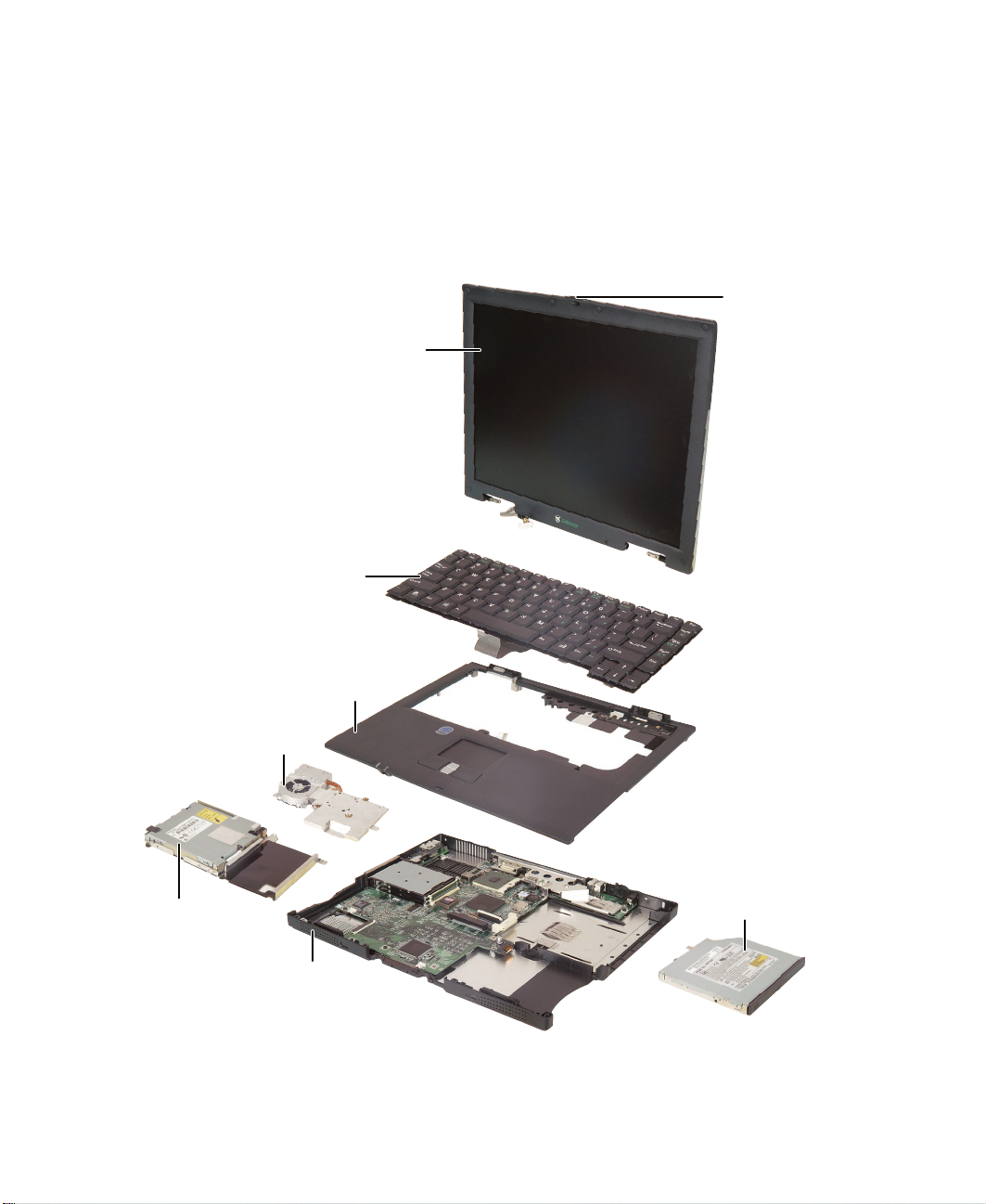
Use this chart to identify the main components of your notebook. For a
complete list of replaceable parts, see “Contents” on page i.
LCD panel assembly
(see page 24)
Keyboard
(see page 32)
LCD panel latch
(see page 27)
Cooling assembly
(see page 37)
Diskette drive
(see page 51)
2
Palm rest assembly
(see page 45)
CD or DVD drive
(see page 42)
System board
(see page 56)
www.gateway.com
Page 8

Preparing your work space
Bef ore perf orming mainte nance o n your n otebook , make s ure you r work s pace
and your notebook are correctly prepared.
■ Wear a grounding (ESD) wrist strap.
■ Use a grounded or dissipative work mat.
■ Use a stable and strong table.
■ Make sure the table top is large enough to hold each component as you
remove it.
■ Use bright lighting to make part identification easier.
■ Keep your work surface free from clutter and dust that may damage
components.
■ Use a magnetized screwdriver for removing screws.
■ As you remove components and screws, lay them toward the rear of your
work surface (behind your notebook) or far enough to the side that your
arms do not accidentally brush components onto the floor.
Preparing your work space
■ To help keep track of screws, try the following:
■ Place each component’s screws in their own section of a parts
sorter.
■ Place each component’s screws next to the component on your
work surface.
■ Print the first page of each task, then place the page toward the
rear of your work surface. As you remove screws, place the screws
in their respective boxes on the page. Where screw measurements
are shown, the first number indicates screw head width, and the
second number indicates screw length.
■ When you place flat-headed screws on your work surface, stand
them on their heads to prevent the screws from rolling off the table.
www.gateway.com
3
Page 9
Chapter : Replacing Components in Your Gateway Solo 1450
Preventing static electricity discharge
The components inside your notebook are extremely sensitive to static
electricity, also known as electrostatic discharge (ESD).
Caution ESD can permanently damage electrostatic discharge
sensitive components in your notebook. Prevent ESD
damage by following ESD guidelines every time you open
your notebook case.
Warning To avoid exposure to dangerous electrical voltages and
moving parts, turn off your notebook, remove the battery,
and unplug the power cord and modem cable before
opening the case.
Before replacing components, follow these guidelines:
Warning To prevent risk of electric shock, do not insert any object
into the vent holes of your notebook.
■ Turn off your notebook power.
■ Remove the battery and unplug the power cord.
■ Disconnect all peripheral devices and remove any PC Cards.
■ Wear a grounding wrist strap (available at most electronics stores) and
attach it to a bare metal part of your workbench or other grounded
connection.
■ Touch a bare metal surface on your workbench or other grounded object.
■ Avoid static-causing surfaces such as carpeted floors, plastic, and packing
foam.
■ Remove components from their antistatic bags only when you are ready
to use them. Do not lay components on the outside of antistatic bags
because only the inside of the bags provide electrostatic protection.
■ Always hold memory modules and modems by their edges, but avoid
touching the edge connectors and components on the cards.
■ Never slide any component over any surface.
4
www.gateway.com
Page 10
Preparing your notebook
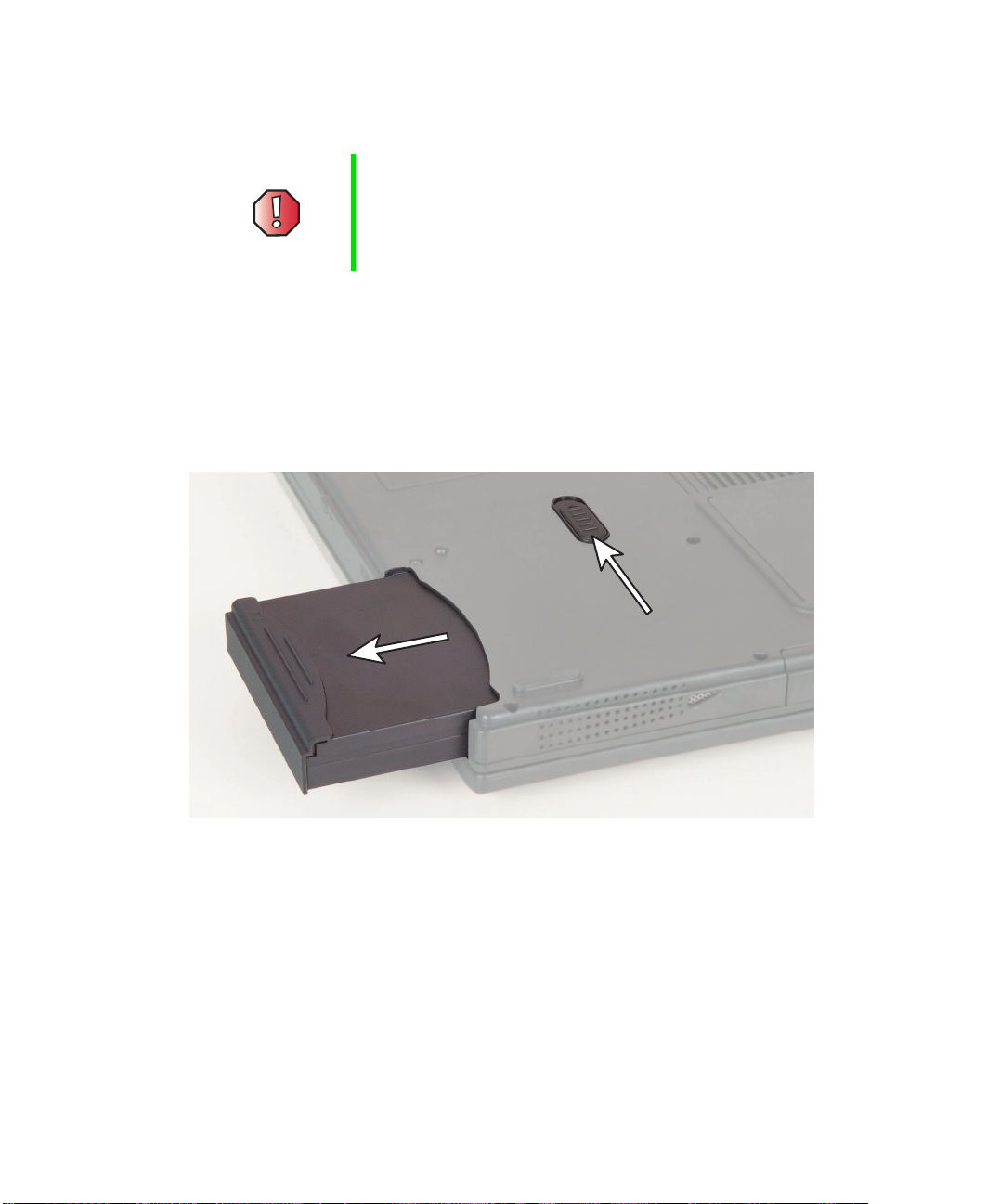
Warning To avoid exposure to dangerous electrical voltages and
moving parts, turn off your notebook, remove the battery,
and unplug the power cord and modem cable before
opening the case. Replace the cover before you restore
power or reconnect the modem cable.
To prepare your notebook for maintenance:
■ Make sure the CD or DVD drive and the diskette drive are empty.
■ Disconnect all peripheral devices and remove any PC Cards.
■ Turn off your notebook and unplug the power cable (if attached).
■ Turn over your notebook and remove the battery.
Preparing your work space
www.gateway.com
5
Page 11
Chapter : Replacing Components in Your Gateway Solo 1450
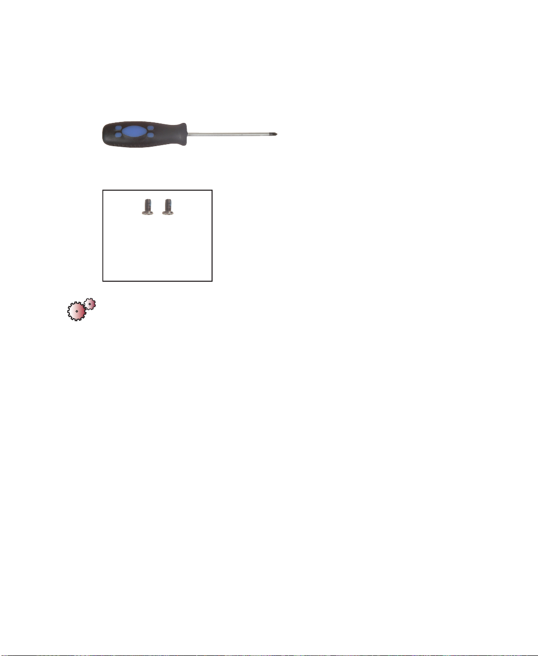
Replacing the hard drive kit
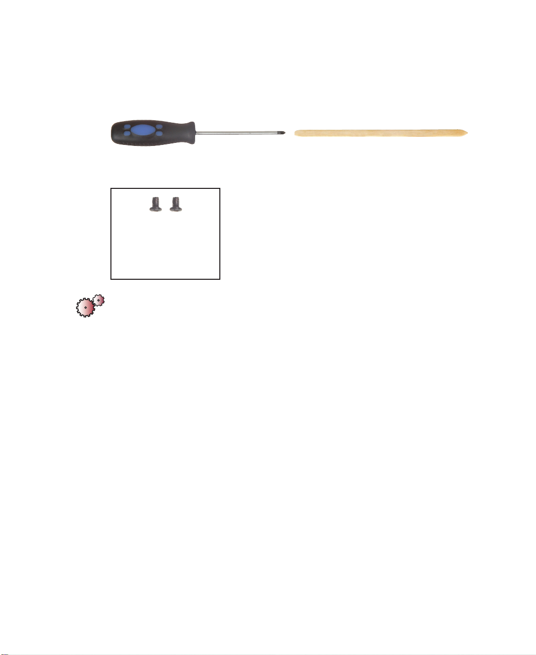
Tools you need to complete this task:
Phillips #0 screwdriver
Screws removed during this task:
2 black 2.5 × 5 mm
(hard drive)
To replace the hard drive kit:
1 Disconnect the power cord, remove the battery, and prepare your
notebook by following the instructions in “Preparing your notebook” on
page 5.
2 Turn your notebook over so that the bottom is facing up.
6
www.gateway.com
Page 12

Replacing the hard drive kit
3 Remove the two black screws that secure the hard drive kit to your
notebook.
Black screws
4 Slide the hard drive kit out of your notebook.
5 Insert the new hard drive kit and replace the two screws.
www.gateway.com
7
Page 13
Chapter : Replacing Components in Your Gateway Solo 1450
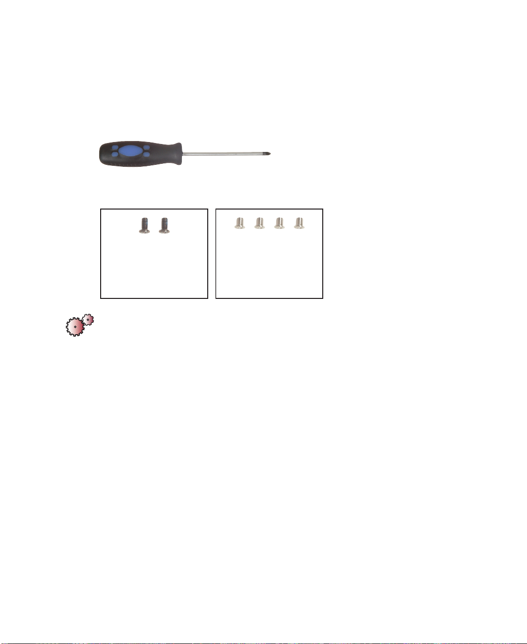
Replacing the hard drive in the hard drive kit
Tools you need to complete this task:
Phillips #0 screwdriver
Screws removed during this task:
2 black 2.5 × 5 mm
(hard drive)
4 chrome 3 × 3.5 mm
(hard drive)
To install a new hard drive into the kit:
1 Disconnect the power cord, remove the battery, and prepare your
notebook by following the instructions in “Preparing your notebook” on
page 5.
2 Remove the hard drive kit by following the instructions in “Replacing
the hard drive kit” on page 6.
8
www.gateway.com
Page 14
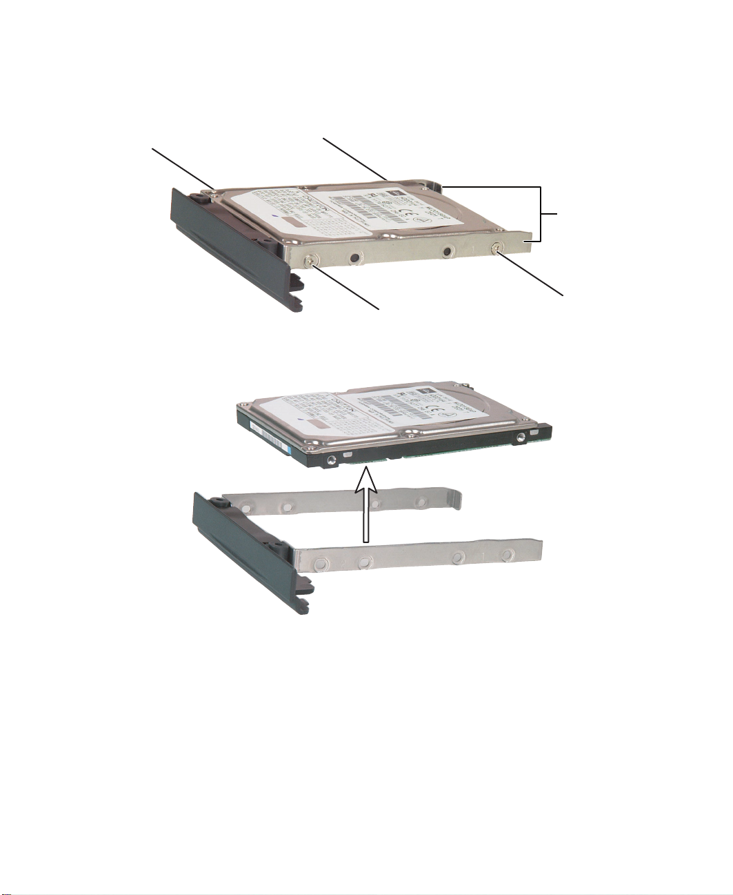
Replacing the hard drive in the hard drive kit
3 Remove the four screws that secure the hard drive to the hard drive kit
bracket.
Chrome screw
Chrome screw
Chrome screw
4 Remove the old drive from the bracket.
Bracket
Chrome screw
www.gateway.com
9
Page 15
Chapter : Replacing Components in Your Gateway Solo 1450
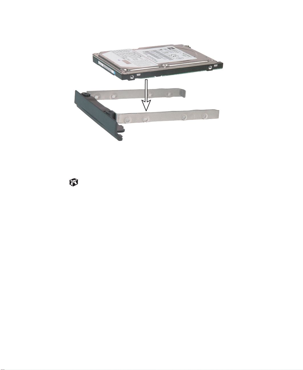
5 Insert the new drive into the bracket so that the screw holes line up.
6 Replace the four screws that secure the bracket to the drive.
7 Insert the hard drive kit into your notebook and replace the two screws
that secure the kit to your notebook.
10
www.gateway.com
Page 16
Adding or replacing memory modules
Adding or replacing memory
modules
Tools you need to complete this task:
Phillips #0 screwdriver
Important Use only PC100 (100 MHz) or PC133 (133 MHz) memory
modules.
To add or replace memory modules:
1 Disconnect the power cord, remove the battery, and prepare your
notebook by following the instructions in “Preparing your notebook” on
page 5.
2 Turn your notebook over so that the bottom is facing up.
www.gateway.com
11
Page 17
Chapter : Replacing Components in Your Gateway Solo 1450
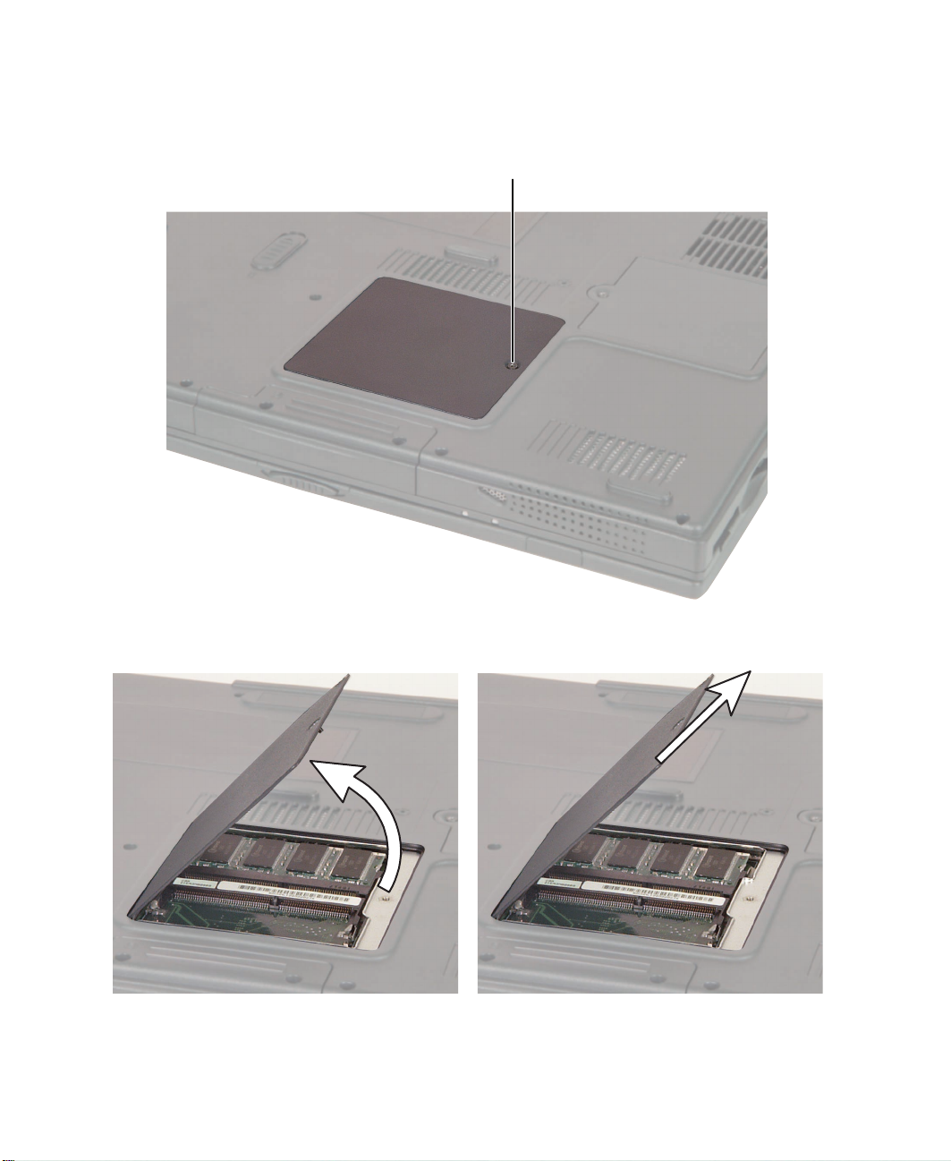
3 Loosen the captive screw that secures the memory cover. (The screw
cannot be removed.)
Captive screw
12
4 Tilt the screw side of the cover upward, then slide the cover out.
www.gateway.com
Page 18
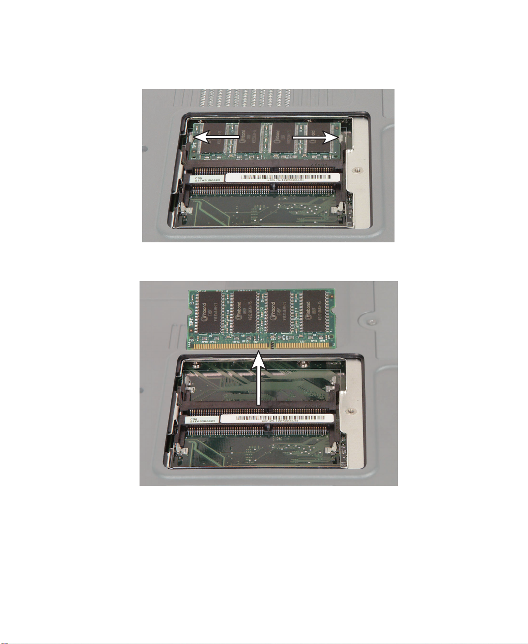
Adding or replacing memory modules
5 To remove a module, press outward on the clips at both ends of the
memory module until the module tilts upward.
6 Pull the memory module out of the slot.
www.gateway.com
13
Page 19
Chapter : Replacing Components in Your Gateway Solo 1450
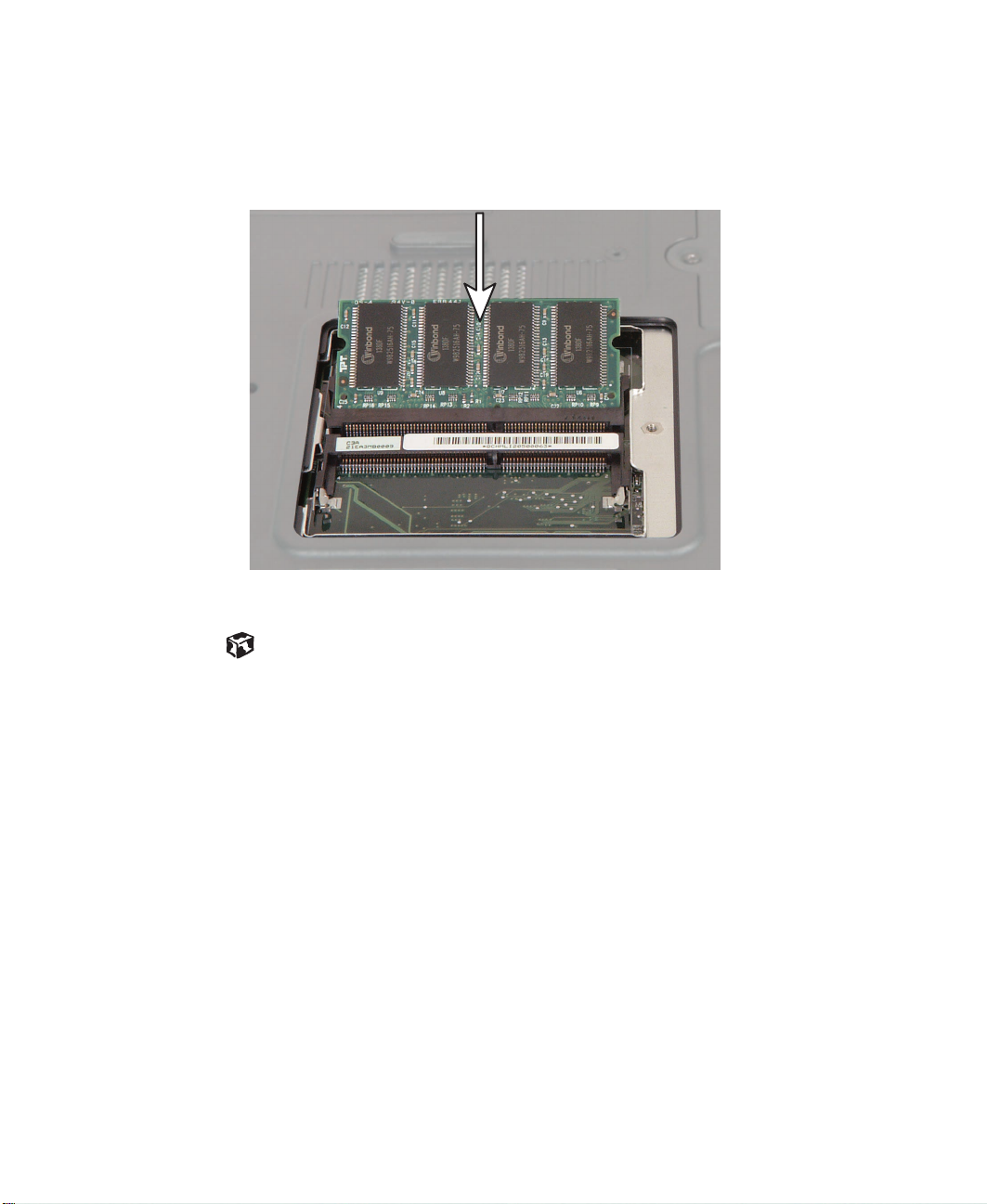
7 Hold the new or replacement module at a 30-degree angle and press it
into the empty memory slot. This module is keyed so that it can only
be inserted in one direction. If the module does not fit, make sure the
notch in the module lines up with the tab in the memory bay.
14
8 Replace the memory cover, then tighten the captive screw.
www.gateway.com
Page 20
Replacing the modem
Tools you need to complete this task:
Phillips #0 screwdriver Scribe or non-marring tool
Screws removed during this task:
2 black 2.5 × 4 mm
(modem)
To replace the modem:
Replacing the modem
1 Disconnect the power cord, remove the battery, and prepare your
notebook by following the instructions in “Preparing your notebook” on
page 5.
2 Turn your notebook over so that the bottom is facing up.
www.gateway.com
15
Page 21
Chapter : Replacing Components in Your Gateway Solo 1450
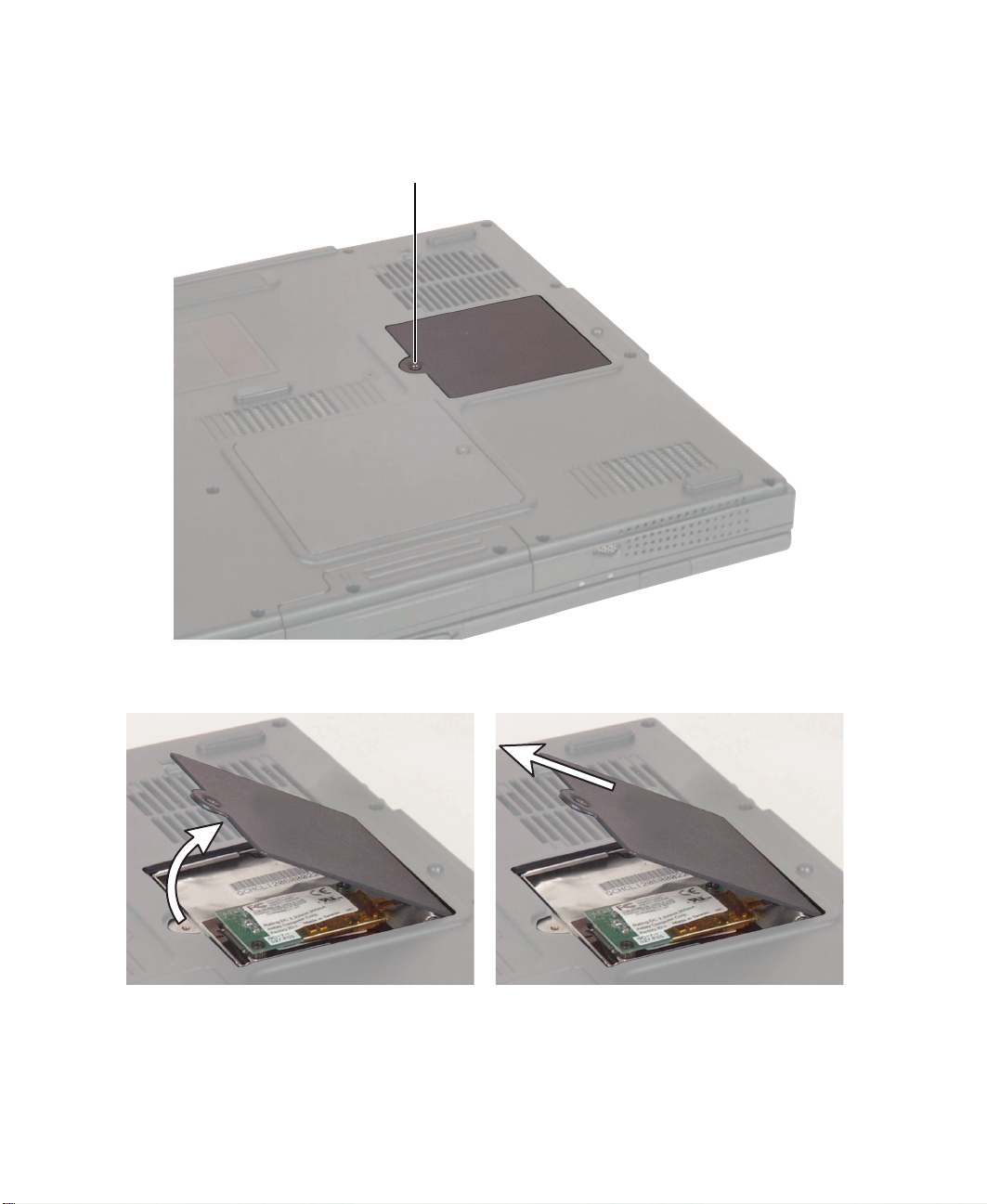
3 Loosen the captive screw that secures the modem cover. (The screw
cannot be removed.)
Captive screw
16
4 Tilt the screw side of the cover upward, then slide the cover out.
www.gateway.com
Page 22
Replacing the modem
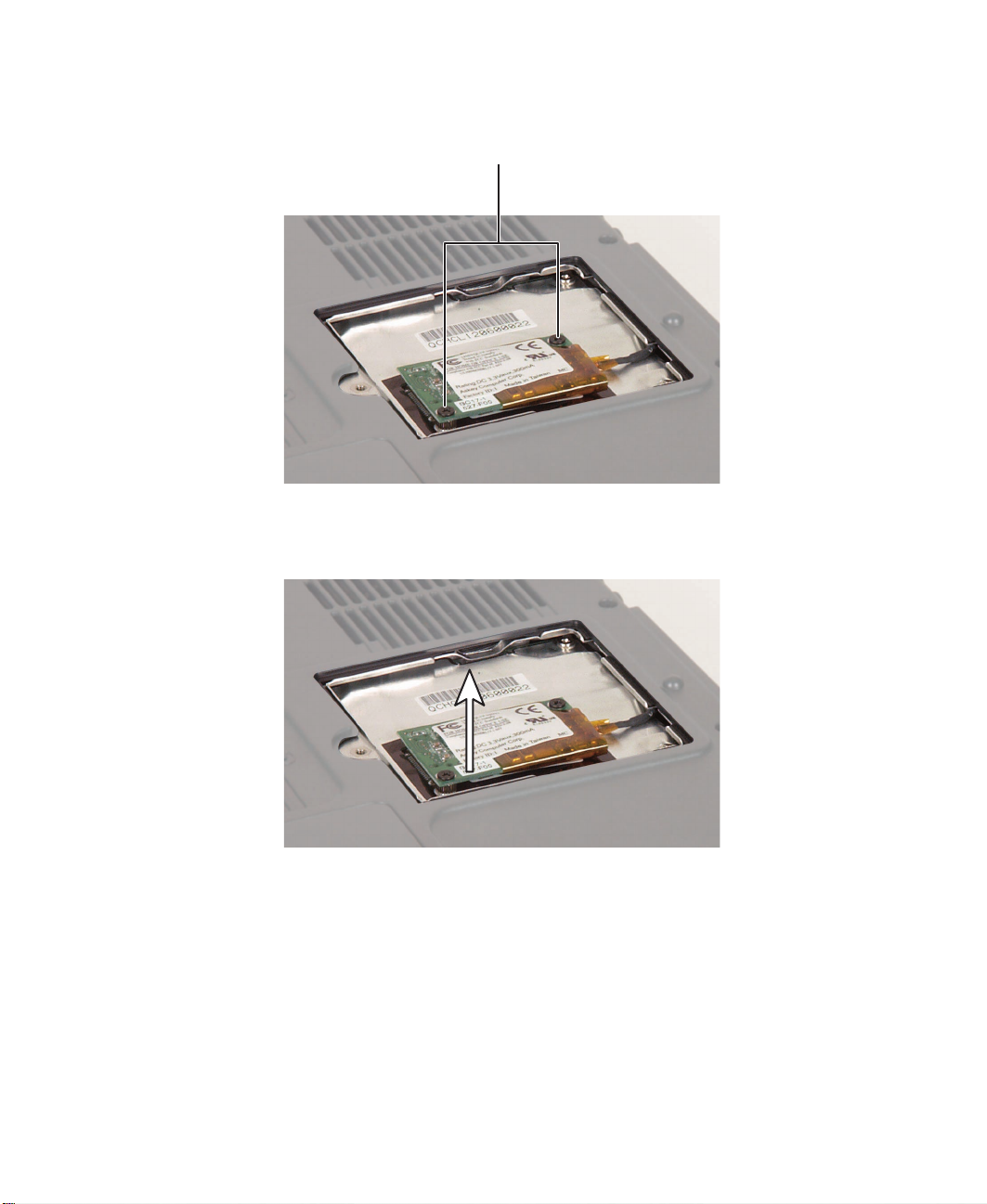
5 Remove the two black screws that secure the modem to your notebook.
Black screws
6 Use a scribe or small flat-blade screwdriver to lift the modem out of your
notebook.
www.gateway.com
17
Page 23

Chapter : Replacing Components in Your Gateway Solo 1450
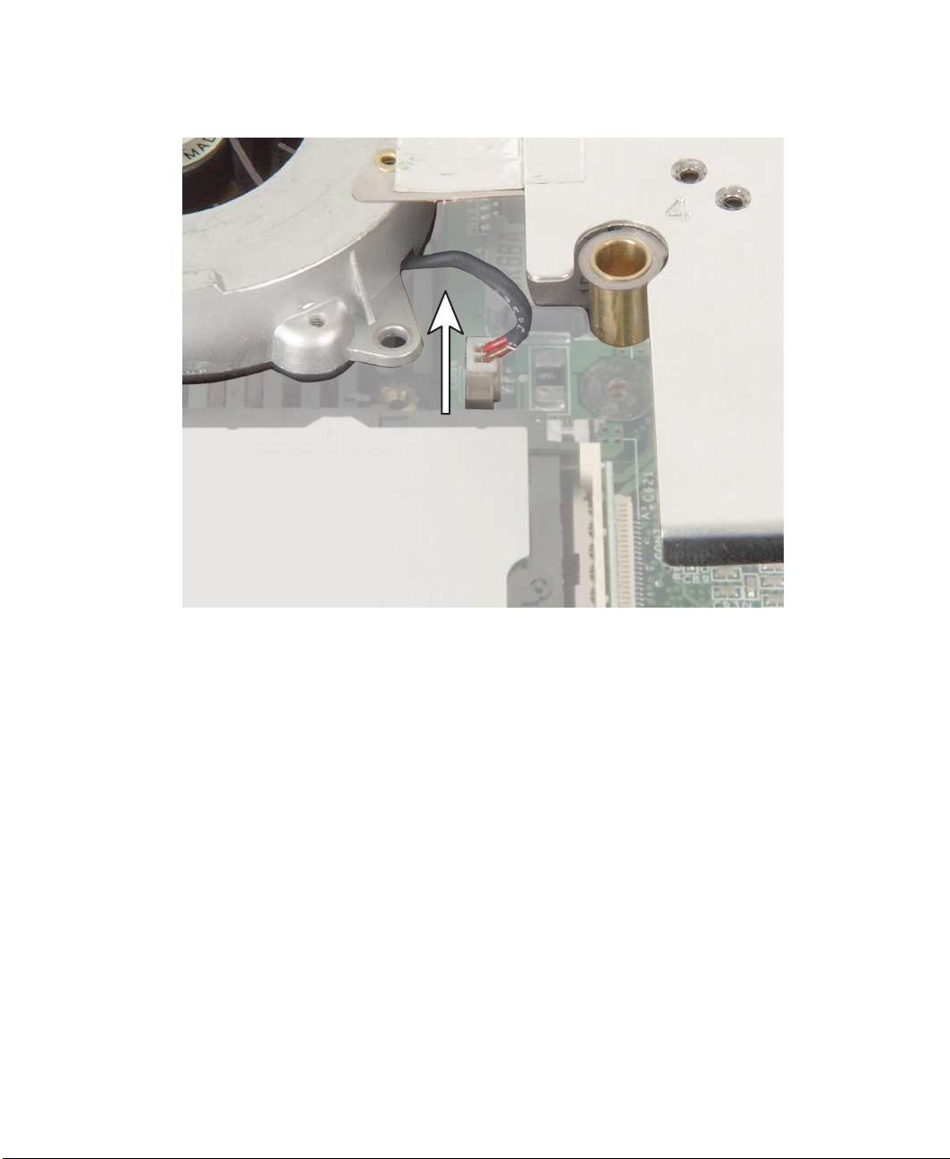
7 Carefully disconnect the modem cable from the modem.
8 Connect the modem cable to the new modem, then align the modem’s
screw holes with the holes on your notebook and press the modem into
place.
18
9 Replace the two black screws that secure the modem to your notebook.
10 Replace the cover, then tighten the captive screw.
www.gateway.com
Page 24

Replacing the keyboard cover
Replacing the keyboard cover
Tools you need to complete this task:
Flat-blade screwdriver Scribe or non-marring tool- OR -
To replace the keyboard cover:
1 Disconnect the power cord, remove the battery, and prepare your
notebook by following the instructions in “Preparing your notebook” on
page 5.
2 Open your notebook.
3 Insert a flat-blade screwdriver or non-marring tool into the small notch
in the bottom of the keyboard cover just above and between the Ins and
Del keys, then carefully pry the cover up.
Important To prevent damage to your notebook while using a
screwdriver, insert a piece of cloth between the
screwdriver, the keyboard, and your notebook case.
www.gateway.com
19
Page 25

Chapter : Replacing Components in Your Gateway Solo 1450
4 Lift the right end of the cover, then slide the cover off to your right.
5 Slide the left edge of the new cover into the left side of your notebook
above the keyboard.
20
6 Press down at the locations shown until the cover clicks into place.
Press PressPress
www.gateway.com
Page 26

Replacing the hinge covers
Tools you need to complete this task:
Phillips #0 screwdriver Scribe or non-marring tool
Screws removed during this task:
2 black 2.5 × 5 mm
(left hinge cover)
1 chrome 2.5 × 6 mm
(right hinge cover)
To replace the hinge covers:
Replacing the hinge covers
1 Disconnect the power cord, remove the battery, and prepare your
notebook by following the instructions in “Preparing your notebook” on
page 5.
2 Remove the keyboard cover by following the instructions in “Replacing
the keyboard cover” on page 19.
3 Open the LCD panel all the way, so that it lies flat on the table.
www.gateway.com
21
Page 27

Chapter : Replacing Components in Your Gateway Solo 1450
4 Remove the two black screws on the left hinge cover and the single
chrome screw on the right hinge cover.
Black screws Chrome screw
22
www.gateway.com
Page 28

Replacing the hinge covers
5 Insert a small screwdriver or non-marring tool underneath the hinge
covers. When you remove the left hinge cover, make sure you pry near
the hinge, not near the screw holes.
6 Pry the hinge covers up.
7 Snap the new covers into place over the hinges, then replace the screws.
www.gateway.com
23
Page 29

Chapter : Replacing Components in Your Gateway Solo 1450
Replacing the LCD panel assembly
Tools you need to complete this task:
Phillips #0 screwdriver Scribe or non-marring tool
Screws removed during this task:
2 black 2.5 × 5 mm
(left hinge cover)
1 chrome 2.5 × 6 mm
(right hinge cover)
4 chrome 2.5 × 6 mm
(hinges)
To replace the LCD panel assembly:
1 chrome 2 × 4 mm
(LCD cable)
24
1 Disconnect the power cord, remove the battery, and prepare your
notebook by following the instructions in “Preparing your notebook” on
page 5.
2 Remove the keyboard cover by following the instructions in “Replacing
the keyboard cover” on page 19.
3 Open the LCD panel all the way, so that it lies flat on the table.
4 Remove the hinge covers by following the instructions in “Replacing the
hinge covers” on page 21.
www.gateway.com
Page 30

5 Remove the screw on the LCD cable plug.
Chrome screw
Replacing the LCD panel assembly
6 Use a scribe or small, flat-blade screwdriver to carefully unplug the LCD
cable.
www.gateway.com
25
Page 31

Chapter : Replacing Components in Your Gateway Solo 1450
7 Remove the four chrome hinge screws (two on each hinge). The LCD
panel is now completely detached from your notebook.
Chrome screws Chrome screws
26
8 Place the new LCD panel assembly onto your notebook, then replace the
four hinge screws.
9 Plug the LCD video cable into your notebook.
10 Reassemble your notebook.
www.gateway.com
Page 32

Replacing the LCD lid latch
Tools you need to complete this task:
Phillips #0 screwdriver
Scribe or non-marring tool
Screws removed during this task:
2 black 2.5 × 5 mm
(left hinge cover)
1 chrome 2.5 × 6 mm
(right hinge cover)
4 chrome 2.5 × 6 mm
(hinges)
1 chrome 2×4mm
(LCD cable)
Replacing the LCD lid latch
Needle nose pliers
6 black 2.5 × 4 mm
(LCD panel face plate)
To replace the LCD lid latch:
1 Disconnect the power cord, remove the battery, and prepare your
notebook by following the instructions in “Preparing your notebook” on
page 5.
2 Remove the keyboard cover by following the instructions in “Replacing
the keyboard cover” on page 19.
3 Remove the hinge covers by following the instructions in “Replacing the
hinge covers” on page 21.
www.gateway.com
27
Page 33

Chapter : Replacing Components in Your Gateway Solo 1450
4 Remove the LCD panel assembly from your notebook by following the
instructions in “Replacing the LCD panel assembly” on page 24.
5 Move your notebook to the side and place the LCD panel assembly
directly in front of you on the table.
6 Use a scribe or other non-marring tool to remove the six screw cover pads.
Place the pads on a clean metal or plastic area of your work table.
Flat pads
28
Rounded pads
7 Remove the six black screws on the LCD panel assembly.
www.gateway.com
Page 34

Replacing the LCD lid latch
8 Insert a scribe or other non-marring tool behind the face plate, then
carefully pry up the face plate until it completely detaches from the rest
of the LCD panel assembly.
www.gateway.com
29
Page 35

Chapter : Replacing Components in Your Gateway Solo 1450
9 Use a pair of needle-nose pliers to pinch the two tabs that hold the latch
together, then pull the latch and spring assembly away from the panel.
Important The LCD latch assembly contains small parts and a strong
spring. While removing the assembly, be careful to keep
the spring on its mounting post or it will fall off the post
and will be difficult to find. You can use a small piece of
tape to help keep the spring in place.
30
10 Remove the latch button from the panel.
www.gateway.com
Page 36

Replacing the LCD lid latch
11 Place the new spring onto the new latch post, then press the new latch
button into the new latch assembly through the slot in the LCD panel.
Make sure the thickest end of the button is on the right.
12 If you have placed tape onto the spring to help keep it in place, remove it.
13 Replace the LCD face plate by lining up the edges and pressing it into
place.
14 Replace the six screws that secure the LCD face plate.
15 Replace the two rounded pads near the hinges, then replace the four flat
pads near the top of the panel.
16 Reassemble your notebook.
www.gateway.com
31
Page 37

Chapter : Replacing Components in Your Gateway Solo 1450
Replacing the keyboard
Tools you need to complete this task:
Phillips #0 screwdriver Scribe or non-marring tool
Screws removed during this task:
2 chrome 2.5 × 3 mm
(keyboard)
To remove the keyboard:
32
1 Disconnect the power cord, remove the battery, and prepare your
notebook by following the instructions in “Preparing your notebook” on
page 5.
2 Remove the keyboard cover by following the instructions in “Replacing
the keyboard cover” on page 19.
www.gateway.com
Page 38

Replacing the keyboard
3 Remove the two chrome screws that secure the keyboard to your
notebook.
Chrome screwChrome screw
4 Raise the back edge of the keyboard slightly, then carefully slide the
keyboard back until the five tabs on the front edge of the keyboard are
free from their slots. Be careful not to damage the LCD panel.
www.gateway.com
33
Page 39

Chapter : Replacing Components in Your Gateway Solo 1450
5 Slowly rotate the keyboard toward you so that it lies keys-down on top
of your notebook. Be careful not to damage the LCD panel.
34
www.gateway.com
Page 40

Replacing the keyboard
6 Pull up on the plastic keyboard connector tabs using two fingers. After
the connector is in the raised position, carefully pull the cable out of the
connector. Be careful not to touch or damage any other components.
Ta bs
7 Place the new keyboard keys-down on your notebook with the space bar
away from you.
8 Pull up on the keyboard connector tabs to verify the connector is in the
raised position.
9 Slide the end of the keyboard cable into the keyboard connector.
Important The keyboard cable should slide easily into the keyboard
connector. The cable is correctly oriented if it is not twisted.
10 Use two fingers to press down on the keyboard connector tabs. This locks
the keyboard cable into the keyboard connector.
www.gateway.com
35
Page 41

Chapter : Replacing Components in Your Gateway Solo 1450
11 Insert the five tabs located on the front edge of the keyboard into the
corresponding slots under the palm rest. Be careful not to damage the
LCD panel.
36
Ta b s
12 Carefully press the keyboard down until it is flat all the way across. The
keyboard should easily fall into place.
13 Replace the two keyboard screws.
14 Reassemble your notebook.
www.gateway.com
Page 42

Replacing the cooling assembly
Replacing the cooling assembly
Tools you need to complete this task:
Phillips #0 screwdriver Scribe or non-marring tool
Screws removed during this task:
2 chrome 2.5 × 3 mm
(keyboard)
4 black 2.5 × 4 mm
1 chrome 2.5 × 6 mm
(fan)
2 black 2.5 × 5 mm
(left cover)
6 chrome 2×4mm
(heat sink)
To replace the cooling assembly:
1 Disconnect the power cord, remove the battery, and prepare your
notebook by following the instructions in “Preparing your notebook” on
page 5.
2 Remove the keyboard cover by following the instructions in “Replacing
the keyboard cover” on page 19.
3 Remove the keyboard by following the instructions in “Replacing the
keyboard” on page 32.
4 Remove the left hinge cover by following the instructions in “Replacing
the hinge covers” on page 21.
www.gateway.com
37
Page 43

Chapter : Replacing Components in Your Gateway Solo 1450
5 Remove the four black screws and one chrome screw on the cooling fan,
then remove the six chrome screws on the heat sink.
Fan
Black screws
Chrome screws (#3 and #6) Chrome screws (#1 and #2)
Heat
sink
38
Black screws
Chrome screws (#4 and #5)
www.gateway.com
Page 44
6 Unplug the cooling fan.
Replacing the cooling assembly
www.gateway.com
39
Page 45

Chapter : Replacing Components in Your Gateway Solo 1450
7 Lift the part of the cooling assembly that is closest to you, then pull it
out toward you.
Important If the cooling assembly gets stuck under the plastic near
the heat sink’s screw hole marked 2, use a scribe or other
non-marring tool to carefully pry the plastic away from the
assembly.
40
8 Insert the new cooling assembly into your notebook, then plug in the
cooling fan.
www.gateway.com
Page 46

Replacing the cooling assembly
Warning When replacing the heat sink’s chrome screws into the
numbered holes, tighten them in numerical order.
9 Replace the cooling assembly screws. Make sure you tighten the heat
sink’s chrome screws in numerical order. Each screw hole has a numeral
next to it.
10 Reassemble your notebook.
www.gateway.com
41
Page 47

Chapter : Replacing Components in Your Gateway Solo 1450
Replacing the CD or DVD drive
Tools you need to complete this task:
Phillips #0 screwdriver Scribe or non-marring tool
Screws removed during this task:
1 chrome 2×4mm
(CD or DVD drive top)
2 chrome 2.5 × 3 mm
(keyboard)
To replace the CD or DVD drive:
1 black 2.5 × 4 mm
(CD or DVD drive bottom)
42
1 Disconnect the power cord, remove the battery, and prepare your
notebook by following the instructions in “Preparing your notebook” on
page 5.
2 Remove the keyboard cover by following the instructions in “Replacing
the keyboard cover” on page 19.
3 Remove the keyboard by following the instructions in “Replacing the
keyboard” on page 32.
www.gateway.com
Page 48

Replacing the CD or DVD drive
4 Remove the chrome screw and the black screw that secure the CD or DVD
drive to your notebook.
Chrome screw
Black screw
www.gateway.com
43
Page 49

Chapter : Replacing Components in Your Gateway Solo 1450
5 Slide the CD or DVD drive out of your notebook.
44
6 Insert the new CD or DVD drive.
7 Replace the two screws that secure the CD or DVD drive to your
notebook.
8 Reassemble your notebook.
www.gateway.com
Page 50

Replacing the palm rest assembly
Replacing the palm rest assembly
Tools you need to complete this task:
Phillips #0 screwdriver Scribe or non-marring tool
Screws removed during this task:
2 black 2.5 × 5 mm
(left hinge cover)
2 black 2.5 × 5 mm
(hard drive)
2 chrome 2.5 × 3 mm
(keyboard)
1 chrome 2.5 × 6 mm
(right hinge cover)
4 chrome 2.5 × 6 mm
(hinges)
13 black 2.5 × 5 mm
(palm rest bottom)
1 chrome 2 × 4 mm
(LCD cable)
3 black 2.5 × 5 mm
(palm rest back)
www.gateway.com
2 chrome 2.5 × 6 mm
(palm rest top)
45
Page 51

Chapter : Replacing Components in Your Gateway Solo 1450
To replace the palm rest:
1 Disconnect the power cord, remove the battery, and prepare your
notebook by following the instructions in “Preparing your notebook” on
page 5.
2 Remove the hard drive kit by following the instructions in “Replacing
the hard drive kit” on page 6.
3 Remove the keyboard cover by following the instructions in “Replacing
the keyboard cover” on page 19.
4 Remove the keyboard by following the instructions in “Replacing the
keyboard” on page 32.
5 Remove the hinge covers by following the instructions in “Replacing the
hinge covers” on page 21.
6 Remove the LCD panel by following the instructions in “Replacing the
LCD panel assembly” on page 24.
46
www.gateway.com
Page 52

Replacing the palm rest assembly
7 Remove the thirteen black screws on the bottom of your notebook. If
you can loosen the screw nearest the memory cover but you cannot
completely remove it, either leave it in place or use a scribe or other
non-marring tool to remove it.
Black screws
Black
screws
Black screw nearest to
the memory cover
Black
screws
Black screws
www.gateway.com
47
Page 53

Chapter : Replacing Components in Your Gateway Solo 1450
8 Turn your notebook over, then remove the three black screws on the back
of your notebook.
Black screws
9 Remove the chrome screws above the touchpad and next to the left
hinge.
Chrome screws
48
www.gateway.com
Page 54

Replacing the palm rest assembly
10 Unplug the touchpad’s ribbon cable from your notebook.
www.gateway.com
49
Page 55

Chapter : Replacing Components in Your Gateway Solo 1450
11 Lift the palm rest assembly away from your notebook.
50
12 Place the new palm rest onto your notebook.
13 Attach the new palm rest’s ribbon cable to your notebook, then replace
all of the palm rest’s screws.
14 Reassemble your notebook.
www.gateway.com
Page 56

Replacing the diskette drive
Replacing the diskette drive
Tools you need to complete this task:
Phillips #0 or #1 screwdriver
Screws removed during this task:
2 black 2.5 × 5 mm
(hard drive)
4 chrome 2.5 × 6 mm
(hinges)
2 chrome 2.5 × 3 mm
(keyboard)
1 chrome 2×4mm
(LCD cable)
Scribe or non-marring tool
2 black 2.5 × 5 mm
(left hinge cover)
1 chrome 2.5 × 6 mm
(right hinge cover)
2 chrome 2.5 × 6 mm
(palm rest top)
13 black 2.5 × 5 mm
(palm rest bottom)
4 black 2.5 × 4 mm
(diskette drive)
3 black 2.5 × 5 mm
(palm rest back)
www.gateway.com
51
Page 57

Chapter : Replacing Components in Your Gateway Solo 1450
To replace the diskette drive:
1 Disconnect the power cord, remove the battery, and prepare your
notebook by following the instructions in “Preparing your notebook” on
page 5.
2 Remove the hard drive kit by following the instructions in “Replacing
the hard drive kit” on page 6.
3 Remove the keyboard cover by following the instructions in “Replacing
the keyboard cover” on page 19.
4 Remove the keyboard by following the instructions in “Replacing the
keyboard” on page 32.
5 Remove the palm rest assembly by following the instructions in
“Replacing the palm rest assembly” on page 45.
52
www.gateway.com
Page 58

Replacing the diskette drive
6 Remove the four black screws that secure the diskette drive to your
notebook.
Black screw Black screw
Black screw
www.gateway.com
Black screw
53
Page 59

Chapter : Replacing Components in Your Gateway Solo 1450
7 Lift the diskette drive a few inches from your notebook.
8 Disconnect the diskette drive’s ribbon cable and remove the drive.
54
www.gateway.com
Page 60

Replacing the diskette drive
9 Attach the new diskette drive’s ribbon cable to your notebook, then line
up the drive’s screw holes with your notebook’s screw holes.
10 Replace the four black screws.
11 Reassemble your notebook.
www.gateway.com
55
Page 61

Chapter : Replacing Components in Your Gateway Solo 1450
Replacing the system board
Tools you need to complete this task:
Phillips #0 screwdriver
5.0 mm hex nutdriver
Scribe or non-marring tool
Flat-blade screwdriver
56
www.gateway.com
Page 62

Screws removed during this task:
2 black 2.5 × 5 mm
(hard drive)
2 chrome 2.5 × 3 mm
(keyboard)
Replacing the system board
2 black 2.5 × 5 mm
(left hinge cover)
1 chrome 2.5 × 6 mm
(right hinge cover)
1 chrome 2×4mm
(LCD cable)
4 black 2.5 × 4 mm
(diskette drive)
3 black 2.5 × 5 mm
(palm rest back)
4 chrome 2.5 × 6 mm
(hinges)
13 black 2.5 × 5 mm
(palm rest bottom)
6 chrome 2 × 4 mm
(heat sink)
4 black 2.5 × 4 mm
1 chrome 2.5 × 6 mm
(fan)
2 chrome 2.5 × 6 mm
(palm rest top)
4 black 2.5 × 4 mm
(system board/
LED indicator panel shield)
6 chrome 5 × 9 mm
(rear I/O panel)
www.gateway.com
57
Page 63

Chapter : Replacing Components in Your Gateway Solo 1450
To replace the system board:
1 Disconnect the power cord, remove the battery, and prepare your
notebook by following the instructions in “Preparing your notebook” on
page 5.
2 Remove the hard drive kit by following the instructions in “Replacing
the hard drive kit” on page 6.
3 Remove the memory modules by following the instructions in “Adding
or replacing memory modules” on page 11.
4 Remove the modem by following the instructions in “Replacing the
modem” on page 15.
5 Remove the keyboard cover by following the instructions in “Replacing
the keyboard cover” on page 19.
6 Remove the hinge covers by following the instructions in “Replacing the
hinge covers” on page 21.
7 Remove the LCD panel assembly by following the instructions in
“Replacing the LCD panel assembly” on page 24.
8 Remove the keyboard by following the instructions in “Replacing the
keyboard” on page 32.
58
9 Remove the cooling assembly by following the instructions in “Replacing
the cooling assembly” on page 37.
10 Remove the CD or DVD drive by following the instructions in “Replacing
the CD or DVD drive” on page 42.
The CD or DVD drive and the cooling assembly share a chrome screw.
The chrome screw referenced in Step 4 of “Replacing the CD or DVD
drive” on page 42 was removed in Step 5 of “Replacing the cooling
assembly” on page 37.
11 Remove the palm rest assembly by following the instructions in
“Replacing the palm rest assembly” on page 45.
12 Remove the diskette drive by following the instructions in “Replacing the
diskette drive” on page 51.
www.gateway.com
Page 64

Replacing the system board
13 Remove the six chrome hex nuts on the rear I/O panel.
Chrome hex nuts
14 Unplug the left and right speakers from the system board.
www.gateway.com
59
Page 65

Chapter : Replacing Components in Your Gateway Solo 1450
15 Remove the black LED indicator panel shield screws numbered 2, 4, and
8, then remove the LED indicator panel shield.
Black LED indicator panel shield screws
60
www.gateway.com
Page 66

Replacing the system board
16 Remove the black system board mounting screws numbered 1, 20, 21,
and 23.
Black system board mounting screws
www.gateway.com
61
Page 67

Chapter : Replacing Components in Your Gateway Solo 1450
17 While pushing in on the PC Card eject button, remove the system board.
Make sure the rear I/O panel clears the bottom tray (shown by the top
arrow) and the side audio jacks clear the bottom tray (shown by the left
arrow).
62
www.gateway.com
Page 68

Replacing the system board
18 Use a flat-blade screwdriver to turn the processor lock screw ¼-turn
counter-clockwise, then remove the processor from the old system board.
www.gateway.com
63
Page 69

Chapter : Replacing Components in Your Gateway Solo 1450
19 Install the processor into the new system board making sure that Pin 1
on the processor (indicated by the silk-screened arrow on the corner of
the processor) aligns with Pin 1 on the processor socket (indicated by the
absence of a pin hole in the processor socket), then lock the processor
in place by using a flat-blade screwdriver to turn the processor lock screw
¼-turn clockwise.
Pin 1
64
Pin 1
www.gateway.com
Page 70

Replacing the system board
20 Place the new system board onto your notebook.
21 Replace the LED indicator panel shield and the three LED indicator panel
shield screws.
22 Replace the four system board mounting screws.
23 Connect the two speaker wires.
24 Replace the six rear I/O panel hex nuts.
25 Reassemble your notebook.
www.gateway.com
65
Page 71

Chapter : Replacing Components in Your Gateway Solo 1450
66
www.gateway.com
Page 72

Page 73

MAN SYS SL1450 SERVICE GDE R1 6/02
 Loading...