

Gast VG-260-08-00 User Manual
MANUFACTURING INCORPORATED
WARNING
PLEASE READ THIS MANUAL COMPLETELY BEFORE INSTALLING AND USING
THIS VACUUM GENERATOR. SAVE THIS MANUAL FOR FUTURE REFERENCE
AND KEEP IN THE VICINITY OF THE VACUUM GENERATOR.
P. O. BOX 97, BENTON HARBOR, MICHIGAN 49023-0097
PHONE 616-926-6171
INSTALLATION and
OPERATING INSTRUCTIONS
FOR PLASTIC MULTI-STAGED
VACUUM GENERATORS
70-8000
E2-150
(Rev. E)
(FOR ORIGINAL EQUIPMENT MANUFACTURERS SPECIAL MODELS CONSULT YOUR LOCAL DISTRIBUTOR)
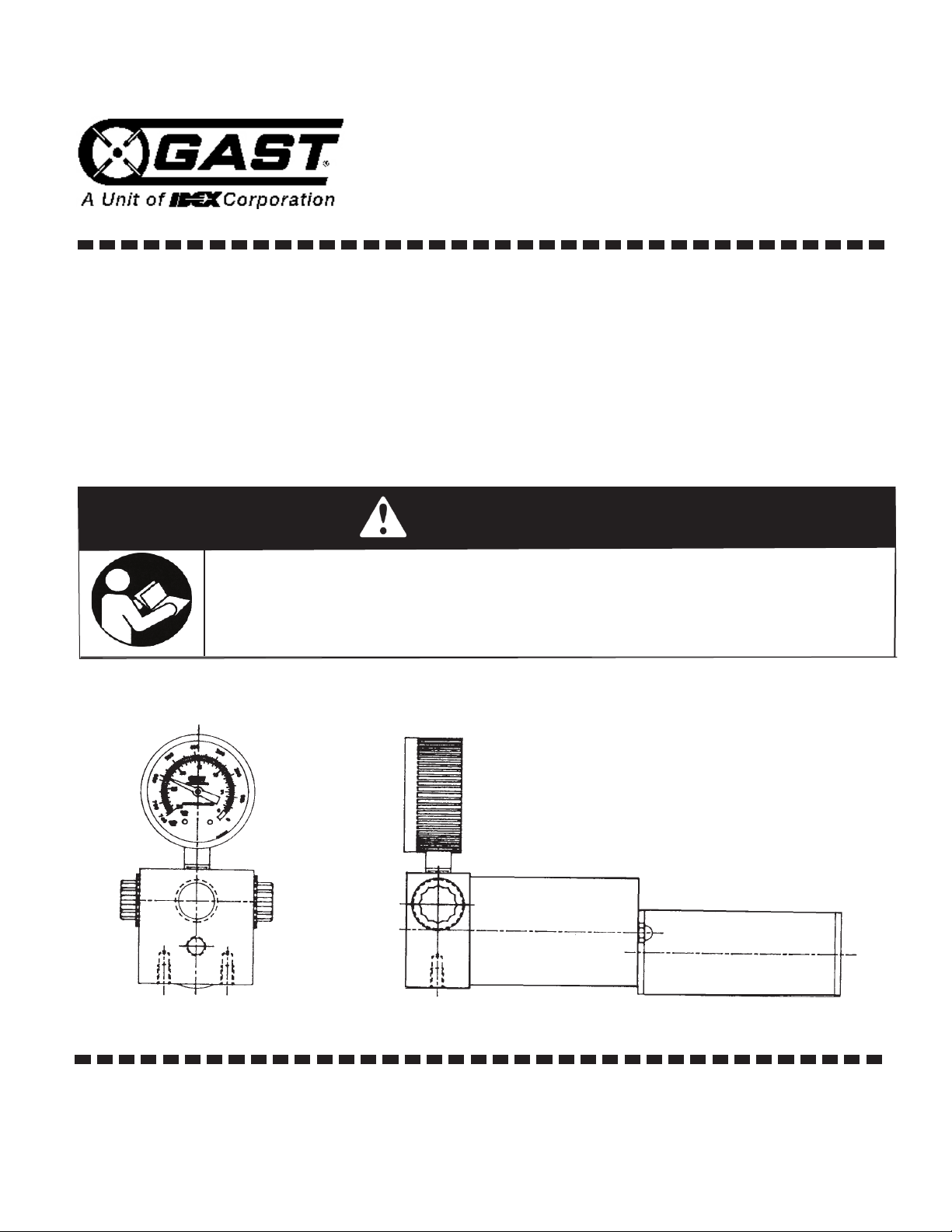
WARNING: Do not pump ammable or explosive gases or operate in an atmosphere
containing them.
INSTALLATION and OPERATING INSTRUCTIONS for
PLASTIC MULTI-STAGED VACUUM GENERATORS
SAFETY
This is the safety alert symbol. When you see this symbol, personal injury is possible. The following signal words show the degree
of injury. Read the information carefully before proceeding.
DANGER Severe personal injury or death will
occur if hazard is ignored.
WARNING Severe personal injury or death can
occur if hazard is ignored.
CAUTION Minor injury or property damage
can occur if hazard is ignored.
GENERAL INFORMATION
Ambient temperature for normal operation should not exceed
125oF (52oC). The low atmospheric pressure at high altitudes re-
duces performance of this unit. Materials used in the construction of
the vacuum generator include Delrin and Neoprene. If the unit will
see substances other than air, consult your local Gast representative for compatibility.
INSTALLATION
CAUTION Supply pressure regulated air to inlet of vacuum generator. Excess pressure can cause parts to burst.
1. The Gast vacuum generator may be mounted in any position
Mounting holes are provided in the aluminum head. Shock
mounting is not required. Round body area must not contact
any rigid frame to maintain alignment.
2. Connect a supply of clean, dry, regulated air to the inlet port in
the aluminum head. Regulator setting should be between
30 and 70 psig (2-5 bar). Best setting is 68 psig (4,6 bar). NO
LUBRICATION should be used with the Gast vacuum
generator.
3. The Gast vacuum generator has multiple inlet ports for con-
nection to the system to be evacuated. Unused ports
should be plugged. Connections to the system must be
equal or larger than the port. Smaller piping will cause lower
vacuum ows. Sealant should be used on all threads to prevent
leakage. Be sure to keep excess sealant from being drawn
into the vacuum generator. Dusty or dirty applications should
have a lter installed to prevent material from being drawn into
the generator. Gast lter AB665 is suggested.
WARNING Restriction of the exhaust air can cause the vacuum
port to become pressurized. Components not designed for full
line pressure can burst causing injury or death.
4. The exhaust port is located in the round end opposite the inlet
port. The mufer supplied should be attached to this port. DO
NOT RESTRICT the outlet of this mufer. This would reduce
both ow and maximum vacuum.
OPERATION
WARNING Solid or liquid material exiting the mufer outlet can
cause eye damage or skin cuts. Keep away from air stream.
To operate the vacuum generator, turn on the regulated air supply.
Air owing through the unit causes vacuum to develop at the intake
ports. Material can enter the vacuum generator either in the compressed air stream or at the vacuum port, it will be ejected through
the exhaust mufer.
Units with multiple stages contain valves which close as vacuum
levels increase. This gives higher ows at low vacuums, reducing
the amount of time required to evauate a system.
Adjust the regulator to 68 psig (4, 5 bar) for best vacuum generation. Block off vacuum line to check for maximum vacuum. Lower
than specied vacuum may be the result of system leaks. If this
condition appears, check and seal leaks.
SERVICING
CAUTION Shut off compressed air supply before servicing.
Parts may burst if air is on when unit is disassembled.
Your Gast vacuum generator requires no scheduled maintenance.
If performance drops, it may require cleaning. In most cases it is
not necessary to remove the vacuum generator from the system.
1. Turn off or disconnect air supply.
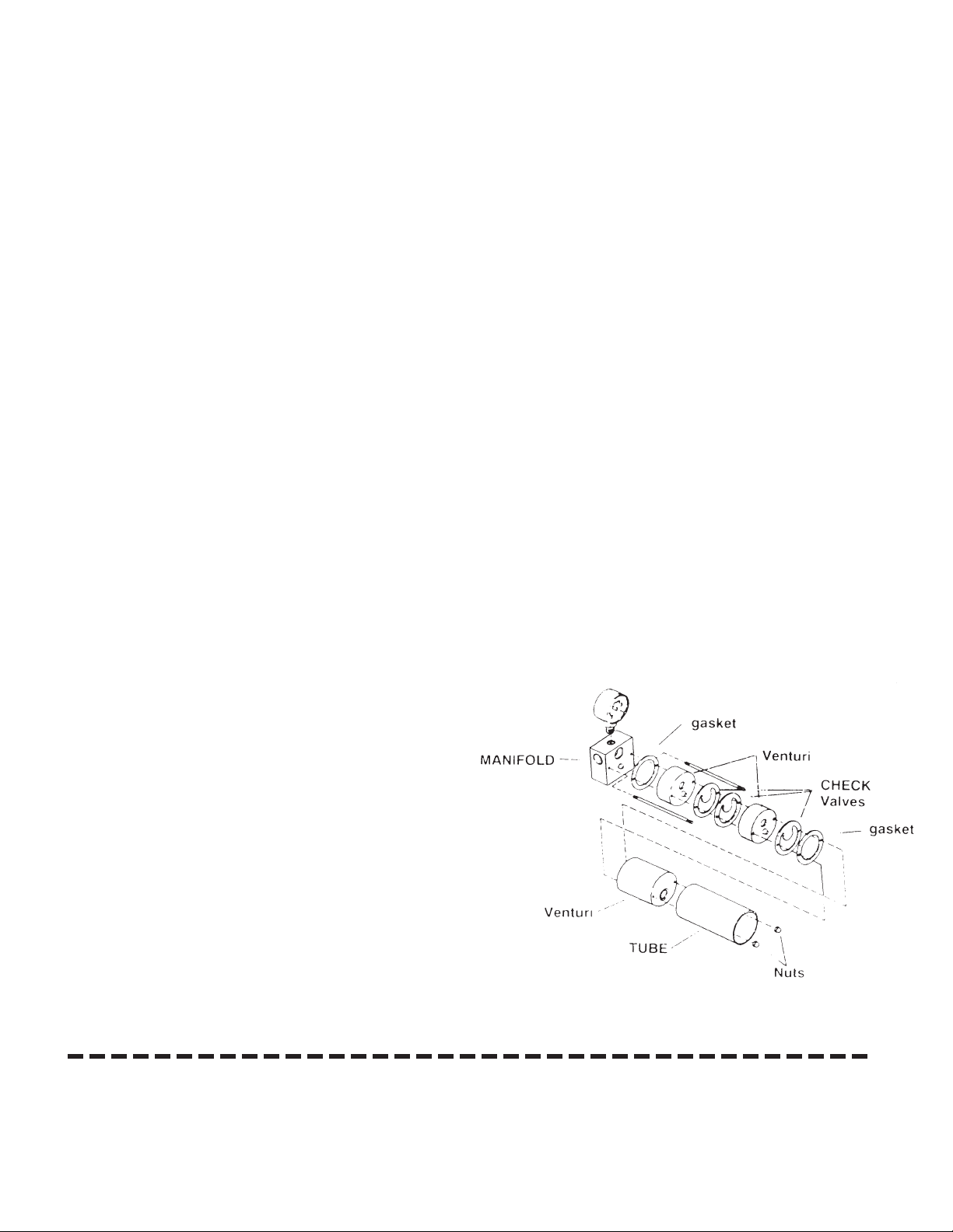
2. Remove mufer. Remove (2) nuts on the exhaust end of the
tie rods.
3. Slip aluminum tube off of round portion. Hold exhaust end in
place while removing tube.
4. Remove each venturi stage and gaskets. Note the position of
each valve, gasket and venturi.
5. Remove any solid material and wash all parts in MILD DE-
TERGENT and WARM WATER to clean. Use of solvents
may damage parts.
6. If new gaskets and valves are required, use Gast Repair
Kit K549. Note not all parts included are required for each
model. Refer to drawing for proper installation.
7. Reassemble in reverse order. Torque nuts to 3in.-lb. (0,3 Nm).
.
We have Gast Certied Service Centers throughout the world. For the most up-to-date listing, contact one of our sales ofces below:
Gast Manufacturing, Inc.
P.O. Box 97
2300 Highway M139
Benton Harbor, MI 49022
Ph: 269/926-6171
FAX: 269/925-8288
www.gastmfg.com
Gast Group Limited, United Kingdom
Unit 11, The I O Centre Nash Road
Redditch, B98 7AS
United Kingdom
ph: +44 (0) 1527 504040
Fax: +44 (0) 1527 525262
www.gastmfg.com
Gast Hong Kong
Unit 12, 21/F, Block B New Trade Plaza
6, On Ping Street, Shatin
N. T. Hong Kong
Ph: (852) 2690 1008
Fax: (852) 2690 1012
www.gasthk.com
 Loading...