

Garmin Smartpump User Manual
SMARTPUMP
Installation Instructions
Important Safety Information
WARNING
See the Important Safety and Product Information guide in the
product box for product warnings and other important
information.
You are responsible for the safe and prudent operation of your
vessel. The autopilot is a tool that enhances your capability to
operate your boat. It does not relieve you of the responsibility of
safely operating your boat. Avoid navigational hazards and
never leave the helm unattended.
Always be prepared to promptly regain manual control of your
boat.
CAUTION
Always wear safety goggles, ear protection, and a dust mask
when drilling, cutting, or sanding.
NOTICE
To avoid damage to your boat, the autopilot system should be
installed by a qualified marine installer. Specific knowledge of
hydraulic steering componentry and marine electrical systems is
required for proper installation.
When drilling or cutting, always check what is on the opposite
side of the surface.
This pump is only for use with Garmin® autopilot systems.
Attempting to use this pump with any other system may damage
the system, the pump, or the vessel.
Mounting Considerations
• Before you start the pump installation, you must identify the
type of hydraulic steering system in your boat and consult the
hydraulic diagrams. Each boat is different, and you must
consider the existing hydraulic layout before deciding where
to mount the pump (Hydraulic Considerations, page 1).
• You should mount the pump horizontally, if possible.
• If you cannot mount the pump horizontally, you must mount it
vertically with the pump head connectors facing up.
• You must mount the pump in a location to which you can
extend the hydraulic steering lines of the boat.
• The pump has five hydraulic-connector fittings, although only
three are used when installing the pump as recommended.
The pump-valve illustration provided in these instructions
may be helpful when determining the fitting layout that is best
for your installation location (Pump Valves and Fittings,
page 1).
Mounting the Pump
Before you mount the pump, if your boat has an unbalanced
cylinder steering system, you must re-configure the pump to
work properly with the unbalanced cylinder (Configuring the
Pump for an Unbalanced Cylinder, page 4).
Before you can mount the pump, you must select a location
(Mounting Considerations, page 1) and determine the correct
mounting hardware (Tools Needed, page 1).
Hold the pump in the intended mounting location and mark
1
the locations of the mounting holes on the mounting surface,
using the pump as a template.
Using a drill bit appropriate for the mounting surface and
2
selected mounting hardware, drill the four holes through the
mounting surface.
Secure the pump to the mounting surface using the selected
3
mounting hardware.
The SmartPump steers your boat by interacting with the
hydraulic steering system, based on commands from the
autopilot system.
Registering Your Device
Help us better support you by completing our online registration
today. Keep the original sales receipt, or a photocopy, in a safe
place.
Go to my.garmin.com/registration.
1
Sign in to your Garmin account.
2
Tools Needed
• Safety glasses
• Drill and drill bits
• Wrenches
• Wire cutter/stripper
• Screwdrivers: Phillips and flat
• Cable ties
• Marine corrosion inhibitor spray
• Hydraulic hose with machine-crimped or field-replaceable
fittings that have a minimum rating of 1000 psi
• Hydraulic T-connectors
• Thread sealant
• Hydraulic bleeding equipment
• Hydraulic fluid
• Mounting screws: the pump kit includes mounting screws, but
if the included screws are not appropriate for the mounting
surface, you must provide the correct types of screws
Hydraulic Considerations
NOTICE
When adding hydraulic line to the system, use only hose with
machine-crimped or field-replaceable fittings that have a
minimum rating of 1000 lbf/in² (6,895 kPa).
Do not use plumber’s tape on any hydraulic fitting. Use an
appropriate thread sealant rated for marine use on all pipe
threads in the hydraulic system.
Do not attempt to use the autopilot to steer the boat until you
bleed all air from each part of the hydraulic system.
Consult the hydraulic-layout diagrams to help determine how to
best install the pump in the hydraulic system of the boat
(Hydraulic Layouts, page 2).
Installing T-fittings and shutoff valves so the pump can be
removed for service without disabling the steering system is
highly recommended. This type of installation uses three of the
five ports on the manifold. Although it is not recommended, all
five ports can be used instead of installing shutoff valves. See
Pump Valves and Fittings, page 1 for more information on the
fittings and alternate connection methods.
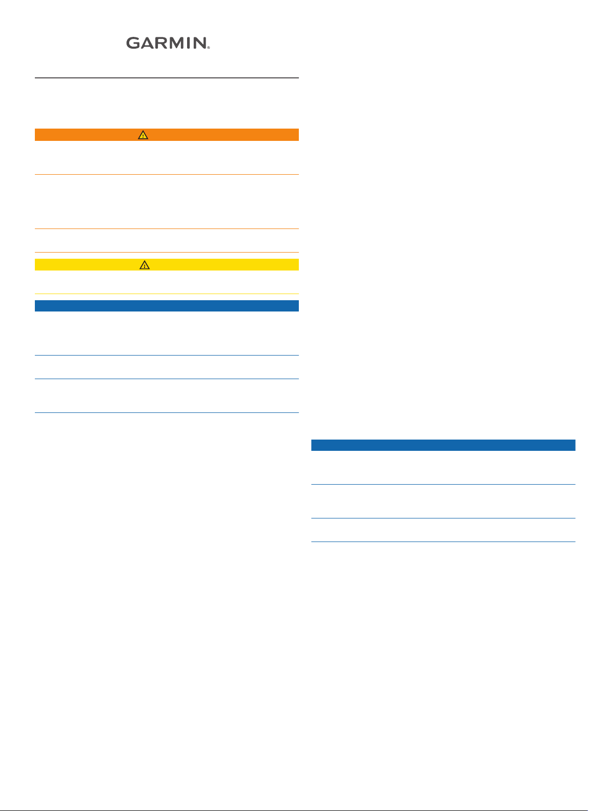
Pump Valves and Fittings
The pump can be connected to the hydraulic system using one
of two methods. The recommended three-connector method
uses only the H1 À and H2 Á fittings, with a T-connector
splitting the connection between the helm and cylinder. The
return line fitting  connects to only the helm. The check valves
should not be reconfigured if the boat is equipped with a
Ã
balanced cylinder. If the boat is equipped with an unbalanced
cylinder, the check valves must be reconfigured (Configuring the
Pump for an Unbalanced Cylinder, page 4). The bypass valve
November 2017
190-02369-02_0A
is opened only for hydraulic bleeding, and must be fully
Ä
tightened during normal operation.
If necessary, the C1 Å and C2 Æ fittings can be used with the
recommended three-connector installation instead of the H1 and
H2 fittings.
Alternatively, the pump can be installed using all five
connectors. This installation option uses the C1 and C2 fittings
to connect the pump to the cylinder and the H1 and H2 fittings to
connect the pump to the helm. This type of installation is not
recommended, because the pump cannot be removed for
service without disabling the steering system of the boat.
Hydraulic Layouts
NOTICE
If the steering system in your boat does not match any of the
hydraulic layouts in this manual and you are unsure how to
install the pump, contact Garmin Product Support.
Before you start the pump installation, identify the type of
hydraulic steering system in your boat. Each boat is different,
and you must consider certain aspects of the existing hydraulic
layout before deciding where to mount the pump.
Important Considerations
• The pump must be reconfigured if the boat is equipped with
an unbalanced steering cylinder (Configuring the Pump for an
Unbalanced Cylinder, page 4).
• Garmin recommends using T-connectors to connect the
hydraulic lines to the pump.
• To allow for easy pump disabling and removal, Garmin
recommends installing shut-off valves in the hydraulic lines
between the pump manifold and T-connectors.
• Teflon® tape must not be used on any hydraulic fitting.
• An appropriate thread sealant should be used on all pipe
threads in the hydraulic system.
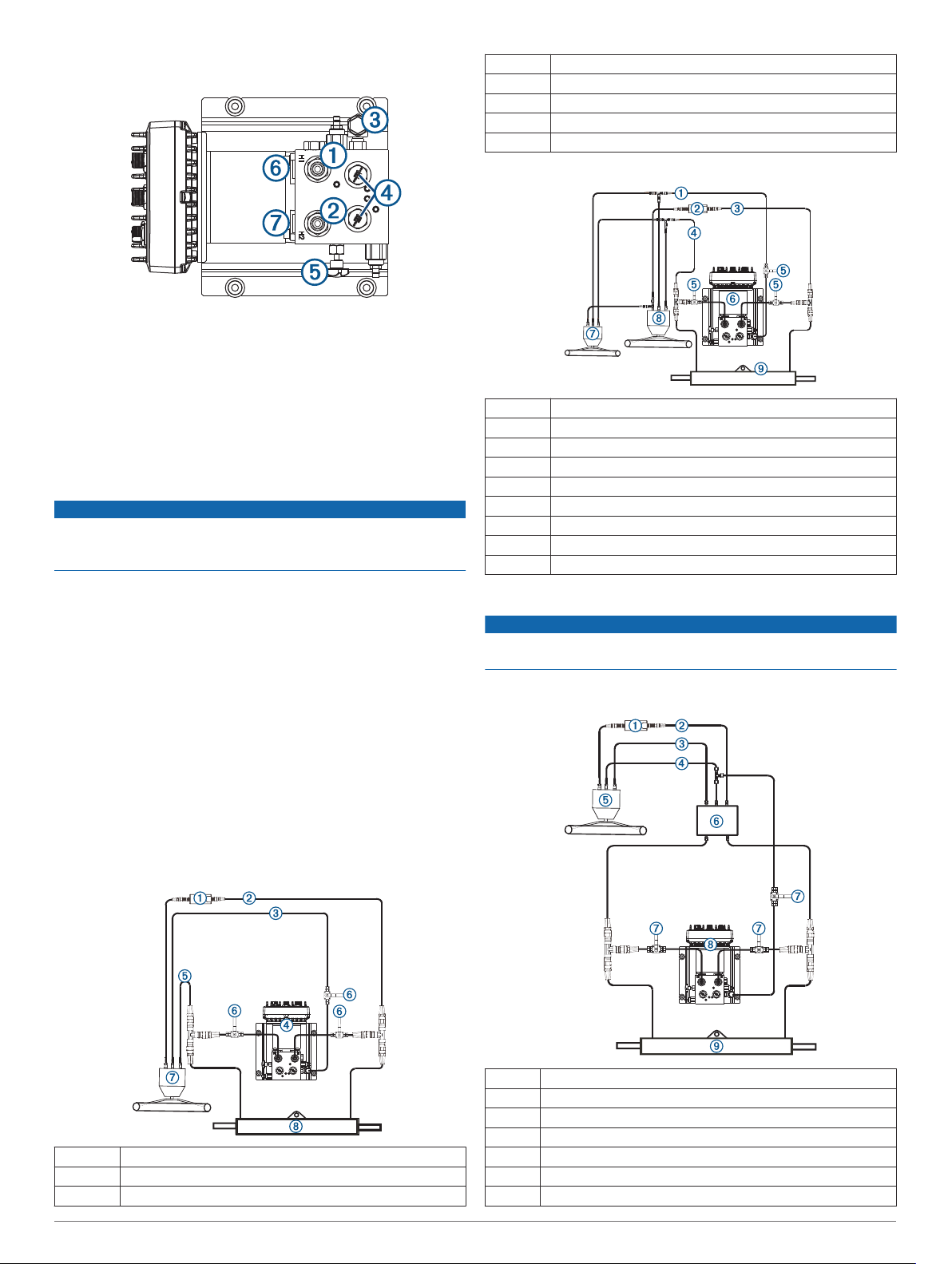
Single-Helm without Power Assist Layout
Ã
Ä
Å
Æ
Ç
Pump
Port line
Shut-off valves
Helm
Steering cylinder
Dual-Helm without Power Assist Layout
À
Á
Â
Ã
Ä
Å
Æ
Ç
È
Return line
Shadow Drive
Starboard line
Port line
Shut-off valves
Pump
Upper helm
Lower helm
Steering cylinder
Single-Helm with Power Assist Layout
NOTICE
The pump must be installed between the cylinder and the
power-assist module to function correctly.
NOTE: Removal of the power assist-module may be necessary
to gain access to the fittings, hoses, and bleed-tee fitting.
À
Á
Â
Ã
À
Á
Â
2
Shadow Drive
Starboard line
Return line
™
Ä
Å
Æ
Shadow Drive
Starboard line
Port line
Return line
Helm
Power-assist module
Shut-off valves
 Loading...