

Garmin SG-DA61500, SG-24DA61500 Installation Manual
®
SG-DA61500/SG-24DA61500 Signature
Series Amplifier Installation
Instructions
Important Safety Information
WARNING
See the Important Safety and Product Information guide in the
product box for product warnings and other important
information.
This device must be installed according to these instructions.
Disconnect the vehicle's or vessel's power supply before
beginning to install this device.
CAUTION
To maintain ignition protection compliance in accordance with
SAE J1171, you must replace the fuse only with a J1171
compliant fuse.
Continuous exposure to sound pressure levels over 100 dBA
may cause permanent hearing loss. The volume is typically too
loud if you cannot hear people speaking around you. Limit the
amount of time you listen at high volume. If you experience
ringing in your ears or muffled speech, stop listening and have
your hearing checked.
Always wear safety goggles, ear protection, and a dust mask
when drilling, cutting, or sanding.
NOTICE
When drilling or cutting, always check what is on the opposite
side of the surface.
The SG-DA61500 device is designed for a 12 Vdc power
source. The SG-24DA61500 device is designed for a 24 Vdc
power source. Connecting to a larger power source may
damage the device.
It is strongly recommended that you have your audio system
installed by a professional installer to ensure optimum
performance.
You must read all installation instructions before beginning the
installation. If you experience difficulty during the installation, go
to www.fusionentertainment.com for product support.
Tools Needed
• Drill and drill bits
• Flat screwdriver
• Wire cutter
• Wire stripper
• 120 A inline fuse or circuit breaker for 12 volt models or 60 A
inline fuse or circuit breaker for 24 volt models
• 4 AWG (21.1 mm2) power cable
NOTE: You may need thicker cable for higher amperages or
longer runs (Power Cable Gauge Guide, page 2).
• 16 AWG (1.31 mm2) speaker wire
NOTE: You may need thicker wire for longer runs (Speaker
Wire Gauge Guide, page 3).
• 20 AWG (0.52 mm2) wire (amplifier turn-on signal)
• Dual RCA cable (1 per zone, for stereo speakers) (Signal and
Speaker Connection Considerations, page 3)
• Single RCA cable and RCA splitter (1 per zone, for mono
subwoofer or bridged output for speakers) (Signal and
Speaker Connection Considerations, page 3)
• Cable ties (optional)
Mounting Considerations
CAUTION
In high ambient temperatures and after extended use, the
device enclosure may reach temperatures deemed dangerous
to touch. Therefore the device must be installed in a location
where it will not be touched during operation.
NOTICE
This device should be mounted in a location that is not exposed
to extreme temperatures or conditions. The temperature range
for this device is listed in the product specifications. Extended
exposure to temperatures exceeding the specified temperature
range, in storage or operating conditions, may cause device
failure. Extreme-temperature-induced damage and related
consequences are not covered by the warranty.
This device is designed for installation only in a dry location.
Installing this device in a location where it may come in contact
with water or become submerged may result in damage. Water
damage is not covered by the warranty.
• The device must be mounted in a location that does not
interfere with the fuel tank or electrical wiring.
• The device must be mounted in a location where it is not
exposed to water.
• The device must be mounted in a location with adequate
ventilation where it is not exposed to extreme temperatures.
• If the device is mounted in an enclosed space, you should
install a cooling fan with appropriate ducts to aid in airflow.
• The device should be mounted so that the cables can be
connected easily.
• To avoid interference with a magnetic compass, the device
should be installed at least 55 cm (22 in.) away from a
compass.
• The device should not be mounted in close proximity to other
navigation-critical equipment, antennas, or radiocommunication equipment on the vessel.
Mounting the SG-DA61500/SG-24DA61500 Signature Series Device
NOTICE
If you are mounting the device in fiberglass, when drilling the
pilot holes, it is recommended to use a countersink bit to drill a
clearance counterbore through only the top gel-coat layer. This
will help to avoid cracking in the gel-coat layer when the screws
are tightened.
NOTE: Screws are included with the device, but they may not
be suitable for the mounting surface.
Before you mount the device, you must select a mounting
location and determine what screws and other mounting
hardware are needed for the surface.
Place the device in the mounting location and mark the
1
location of the pilot holes.
Drill a pilot hole for one corner of the device.
2
Loosely fasten the device to the mounting surface with one
3
corner and examine the other three pilot-hole marks.
GUID-E1123DA0-B5C3-4C9E-84E7-41E2D7952C89 v3July 2020
Mark new pilot-hole locations if necessary, and remove the
4
device from the mounting surface.
Drill the remaining pilot holes.
5
Secure the device to the mounting location.
6
Removing the Cover
You must remove the cover to reach the connectors and
configuration controls on the amplifier.
Using the included 3 mm hex key, remove the screws that
1
secure the cover to the amplifier.
Lift the cover off of the amplifier and set it aside until after you
2
have finished making all of the connections and configured
the amplifier.
Connection Considerations
NOTICE
The wiring (not included) from the battery to the amplifier must
run through an inline fuse or circuit breaker (not included) as
close to the battery as possible. You must connect the positive
wire to the fuse or circuit breaker. Connecting the amplifier to
power without an inline fuse or circuit breaker may result in a fire
if there is a short in the cable.
You must turn off the audio system before making any
connections to the amplifier. Failure to turn off the audio system
may result in damage to the audio system.
All terminals and connections must be protected from contact
with the vessel chassis and with each other. Improper terminal
or wire contact may result in damage to the audio system.
• You must first connect the amplifier to ground before making
any other wiring connections (Connecting to Power,
page 2).
• You must connect the positive wire to the battery only after
you have completed all other wiring to the amplifier.
• If your stereo does not have a remote turn-on signal wire, you
must connect the amplifier to a switched power source.
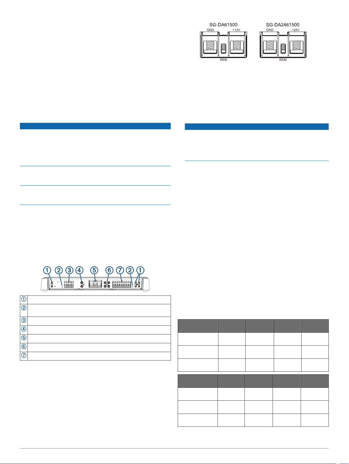
Port Identification
Fuses. See the product specifications for replacement details.
POWER and PROT (protection) LED indicators (Troubleshooting,
page 5)
Zone 1 speaker terminals
Zone 1 RCA input
Power, ground, and amplifier turn-on terminals
Zones 2 and 3 RCA inputs
Zones 2 and 3 speaker terminals
Connecting to Power
You must connect the power wire to the battery through an inline fuse or a circuit breaker.
You must use the appropriate gauge of wire (not included) to
connect the amplifier to power and ground, based on the total
amperage and the length of the cable run (Power Cable Gauge
Guide, page 2).
Route the appropriate gauge of wire to the amplifier and to a
1
ground location on the boat.
Using the included 3 mm hex key, connect the ground wire to
2
the GND terminal on the amplifier.
Connect the other end of the ground wire to the ground
3
location on the boat.
Route the appropriate gauge of wire to the amplifier and to
4
the boat battery, and select an option:
• Install a properly rated in-line fuse on the power wire as
close to the battery as possible.
• Identify or install a circuit breaker, as close to the battery
as possible, for use with the amplifier power wire.
NOTICE
You must not connect the power wire to the amplifier and
battery or circuit breaker before you complete all of the other
connections. Connecting the amplifier to power before you
complete all of the other connections may cause damage to
your audio system.
Select an option:
5
• If your stereo has an amplifier turn-on wire, route a
20 AWG (0.52 mm2) wire from the amplifier turn-on wire
on the stereo to the amplifier.
NOTE: The amplifier and the stereo must connect to the
same physical ground location for the amplifier turn-on
signal to function properly.
• If your stereo does not have an amplifier turn-on wire,
route a 20 AWG (0.52 mm2) wire from the positive
terminal of the battery, through a switch, to the amplifier.
Using the included 2.5 mm hex key, connect the 20 AWG
6
(0.52 mm2) wire to the REM terminal on the amplifier.
Make all of the other connections to the stereo and speakers
before completing the connection to power (Completing the
Connections, page 4).
Power Cable Gauge Guide
You should use 4 AWG (21.1 mm2) wire for most installations. If
your total amperage is higher than 50–65 A, and your cable run
is longer than 10–13 ft (3–4 m), you can use these tables to
determine if you need to use a larger gauge of wire. This table
accounts for terminal connection resistance.
NOTE: If you are using aluminum wire, you should use a wire
two gauges larger than the gauge listed below to compensate
for a potential voltage drop due to the wire material.
Total Amperage 0––4 ft.
(0–1.2 m)
85–105 A 4 AWG
(21.1 mm2)
105–125 A 4 AWG
(21.1 mm2)
125–150 A 2 AWG
(33.6 mm2)
Total Amperage 13–16 ft.
(4–4.9 m)
50–65 A 4 AWG
(21.1 mm2)
65–85 A 2 AWG
(33.6 mm2)
85–105 A 2 AWG
(33.6 mm2)
4–7 ft.
(1.2–2.1 m)
4 AWG
(21.1 mm2)
4 AWG
(21.1 mm2)
2 AWG
(33.6 mm2)
16–19 ft.
(4.9–5.8 m)
4 AWG
(21.1 mm2)
2 AWG
(33.6 mm2)
2 AWG
(33.6 mm2)
7–10 ft.
(2.1–3 m)
4 AWG
(21.1 mm2)
4 AWG
(21.1 mm2)
2 AWG
(33.6 mm2)
19–22 ft.
(5.8–6.7 m)
4 AWG
(21.1 mm2)
2 AWG
(33.6 mm2)
2 AWG
(33.6 mm2)
10–13 ft.
(3–4 m)
2 AWG
(33.6 mm2)
2 AWG
(33.6 mm2)
0 AWG
(53.5 mm2)
22–28 ft.
(6.7–8.5 m)
2 AWG
(33.6 mm2)
0 AWG
(53.5 mm2)
0 AWG
(53.5 mm2)
2 SG-DA61500/SG-24DA61500 Signature Series Installation Instructions
 Loading...