

Garmin SA01535Wi-D Instruction Manual
G1000 / GFC 700
System Maintenance Manual
Hawker Beechcraft
Model 300/B300 Series King Air
Contains Instructions
For Continued Airworthiness
For STC SA01535WI-D
1013
ALT
1000
2992
40
300
60
250
80
200
100
150
190-00716-01 February 2014 Revision 4

This page intentionally left blank.
© Copyright 2012-2014
Garmin Ltd. or its subsidiaries
All Rights Reserved
Except as expressly provided herein, no part of this manual may be reproduced, copied, transmitted,
disseminated, downloaded or stored in any storage medium, for any purpose without the express prior
written consent of Garmin. Garmin hereby grants permission to download a single copy of this manual
and of any revision to this manual onto a hard drive or other electronic storage medium to be viewed and
to print one copy of this manual or of any revision hereto, provided that such electronic or printed copy of
this manual or revision must contain the complete text of this copyright notice and provided further that
any unauthorized commercial distribution of this manual or any revision hereto is strictly prohibited.
Garmin International, Inc.
1200 E. 151
st
Street
Olathe, KS 66062 USA
Telephone: 913-397-8200
www.garmin.com
Garmin (Europe) Ltd.
Liberty House
Bulls Copse Road
Hounsdown Business Park
Southampton, SO40 9RB, UK
Phone: +44 (0) 23 8052 4000
Fax: +44 (0) 23 8052 4004
RECORD OF REVISIONS
Revision Revision Date Description ECO #
1 5/11/12 Initial release -----2 10/24/12 Add sw v0985.06, Add section 3.36 (BLR winglet)
95300
Update Section 4.1 and 4.11
3 6/4/13 Update for GMU 44 installation in horizontal stab. 103013
4 2/21/14 Update for GRS 7800, GTX 3000, GTS Processor 111858
DOCUMENT PAGINATION
Section Pagination
Table of Contents i – viii
Section 1 1-1 – 1-6
Section 2 2-1 – 2-24
Section 3 3-1 – 3-70
Section 4 4-1 – 4-36
Section 5 5-1 – 5-92
Section 6 6-1 – 6-24
Section 7 7-1 – 7-60
Section 8 8-1 – 8-16
Page A G1000 / GFC 700 System Maintenance Manual - 300/B300 Series King Air
Revision 4 190-00716-01

INFORMATION SUBJECT TO EXPORT CONTROL LAWS
This document may contain information which is subject to the Export Administration Regulations
(“EAR”) issued by the United States Department of Commerce (15 CFR, Chapter VII Subchapter C) and
which may not be exported, released or disclosed to foreign nationals inside or outside the United States
without first obtaining an export license. The preceding statement is required to be included on any and
all reproductions in whole or in part of this manual.
WARNING
This product, its packaging, and its components contain chemicals known to the State of California to
cause cancer, birth defects, or reproductive harm. This Notice is being provided in accordance with
California's Proposition 65. If you have any questions or would like additional information, please refer
to our web site at www.garmin.com/prop65
.
CAUTION
The GDU lens is coated with a special anti-reflective coating that is very sensitive to skin oils, waxes and
abrasive cleaners. CLEANERS CONTAINING AMMONIA WILL HARM THE ANTI-REFLECTIVE
COATING. It is very important to clean the lens using a clean, lint-free cloth and an eyeglass lens
cleaner that is specified as safe for anti-reflective coatings.
IMPORTANT
All G1000 screen shots used in this document are current at the time of publication. Screen shots are
intended to provide visual reference only. All information depicted in screen shots, including software
file names, versions and part numbers, is subject to change and may not be up to date.
Page B G1000 / GFC 700 System Maintenance Manual - 300/B300 Series King Air
Revision 4 190-00716-01

TABLE OF CONTENTS
SECTION PAGE
1 INTRODUCTION ............................................................................................................................ 1-1
1.1 C
1.2 O
1.3 D
1.4 P
1.5 R
ONTENT, SCOPE, PURPOSE ........................................................................................................ 1-1
RGANIZATION ............................................................................................................................ 1-3
EFINITIONS/ABBREVIATIONS .................................................................................................... 1-4
UBLICATIONS ............................................................................................................................. 1-5
EVISION AND DISTRIBUTION ..................................................................................................... 1-6
2 SYSTEM DESCRIPTION ............................................................................................................... 2-1
2.1 E
2.2 G1000
2.3 E
2.4 E
2.5 P
2.6 S
2.7 G1000
QUIPMENT DESCRIPTIONS ......................................................................................................... 2-1
OPTIONAL INTERFACES .................................................................................................. 2-14
LECTRICAL POWER DISTRIBUTION .......................................................................................... 2-15
LECTRICAL LOAD UTILIZATION .............................................................................................. 2-18
ITOT/STATIC SYSTEM .............................................................................................................. 2-22
HIELD BLOCK GROUNDS ......................................................................................................... 2-23
/GFC700 BLOCK DIAGRAM ........................................................................................... 2-23
3 G1000 CONTROL & OPERATION ............................................................................................... 3-1
3.1 GDU
3.2 GCU
3.3 GMC
3.4 GMA
3.5 G1000
3.6 R
3.7 C
3.8 G1000
3.9 G1000
3.10 N
3.11 GTS
3.12 GTS
3.13 GTX
3.14 GTX
3.15 GDL
3.16 GSR
3.17 GSR
3.18 GRS
3.19 GRS
3.20 GWX
3.21 GWX
3.22 GMU
3.23 TAWS-A
3.24 TAWS-A
3.25 TAWS-A
3.26 ADF
3.27 DME
3.28 RAD
3.29 N
3.30 L
3.31 L
3.32 ESP
3.33 POTS
1040A AND GDU 1500 DISPLAYS ...................................................................................... 3-1
477 - MFD CONTROLLER ................................................................................................... 3-3
710 - AFCS CONTROLS ...................................................................................................... 3-3
1347D AUDIO PANEL ........................................................................................................ 3-4
NORMAL MODE ................................................................................................................ 3-5
EVERSIONARY MODE ................................................................................................................ 3-6
ONFIGURATION MODE OVERVIEW ............................................................................................ 3-7
/ GFC 700 SOFTWARE INFORMATION ............................................................................ 3-12
SOFTWARE/CONFIGURATION PROCEDURE .................................................................... 3-19
ON-GARMIN TAS/TCAS I TRAFFIC SYSTEM OPTION CONFIGURATION ............................. 3-24
820/850 TRAFFIC SYSTEM CONFIGURATION ................................................................. 3-25
PROCESSOR .................................................................................................................... 3-26
33/33D CONFIGURATION .............................................................................................. 3-27
3000 CONFIGURATION .................................................................................................. 3-28
59 WI-FI DATA LINK OPTION CONFIGURATION ........................................................... 3-29
56 SATELLITE RECEIVER WITH GDL 59 WI-FI DATA LINK OPTION CONFIGURATION . 3-30
56 SATELLITE RECIEVER STAND-ALONE OPTION CONFIGURATION ............................. 3-31
77 AHRS SOFTWARE/CONFIGURATION ........................................................................ 3-32
7800 AHRS SOFTWARE/CONFIGURATION .................................................................... 3-33
68 SOFTWARE/CONFIGURATION .................................................................................. 3-34
70 SOFTWARE/CONFIGURATION .................................................................................. 3-35
44 SOFTWARE/CONFIGURATION .................................................................................. 3-36
SUPPORT CONFIGURATION .................................................................................... 3-37
VOICE NO CALLOUT OPTION CONFIGURATION ..................................................... 3-38
VOICE CALLOUT OPTION CONFIGURATION ........................................................... 3-39
OPTION CONFIGURATION .............................................................................................. 3-40
OPTION CONFIGURATION ............................................................................................. 3-41
ALT OPTION CONFIGURATION ..................................................................................... 3-42
ON-GARMIN TCAS II TRAFFIC SYSTEM OPTION CONFIGURATION .................................... 3-45
IGHTNING SYSTEM OPTION CONFIGURATION ..................................................................... 3-46
IGHTNING SYSTEM OPTION CONFIGURATION LOAD CONFIRMATION ................................. 3-47
SUPPORT OPTION CONFIGURATION................................................................................ 3-49
HANDSET CONFIGURATION ......................................................................................... 3-50
G1000 / GFC 700 System Maintenance Manual - 300/B300 Series King Air Page i
190-00716-01 Revision 4

3.34 FLIGHT DATA RECORDER OPTION CONFIGURATION ............................................................. 3-51
3.35 F
3.36 O
3.37 S
3.38 O
3.39 S
3.40 O
3.41 O
3.42 O
3.43 O
3.44 O
3.45 A
3.46 GDL
3.47 BLR
3.48 S
3.49 N
3.50 C
3.51 C
LITECHARTS CONFIGURATION ............................................................................................. 3-53
PTIONAL CHARTVIEW ENABLE ........................................................................................... 3-53
TANDARD TAWS-B ENABLE ............................................................................................... 3-54
PTIONAL TAWS-A ENABLE ................................................................................................ 3-55
UPPLEMENTAL DATABASE LOADING ................................................................................... 3-56
PTIONAL SVS/PATHWAYS ENABLE ..................................................................................... 3-57
PTIONAL ESP ENABLE ......................................................................................................... 3-58
PTIONAL SEARCH AND RESCUE ENABLE ............................................................................. 3-59
PTIONAL GARMIN TCAS I ENABLE (FROM GTS 825 TO GTS 855) .................................... 3-60
PTIONAL GARMIN TCAS II ENABLE (FROM GTS 825 TO GTS 8000) ................................ 3-61
IRCRAFT REGISTRATION NUMBER ENTRY .......................................................................... 3-62
69 ALTERNATE ANTENNA LOCATION CONFIGURATION ............................................... 3-64
WINGLET OPTION (MODEL 300 ONLY) .......................................................................... 3-65
PLASH SCREEN LOADING ..................................................................................................... 3-66
AVIGATION DATABASE LOADING ....................................................................................... 3-67
ONFIGURATION OF NAVIGATION MAP FOR TRAFFIC SYSTEM ............................................. 3-69
LEARING DEFAULT USER SETTINGS .................................................................................... 3-69
4 INSTRUCTIONS FOR CONTINUED AIRWORTHINESS........................................................ 4-1
4.1 A
4.2 S
4.3 M
4.4 V
4.5 E
4.6 GRS
4.7 GSA
4.8 F
4.9 GSM
4.10 G1000
4.11 E
4.12 T
4.13 G1000
4.14 GIA
4.15 GDU
4.16 S
4.17 R
4.18 E
IRWORTHINESS LIMITATIONS ................................................................................................... 4-1
ERVICING INFORMATION ........................................................................................................... 4-2
AINTENANCE INTERVALS ......................................................................................................... 4-4
ISUAL INSPECTION .................................................................................................................. 4-11
LECTRICAL BONDING TEST ..................................................................................................... 4-16
77 OR GRS 7800 EARTH MAGNETIC FIELD UPDATES ...................................................... 4-19
80 GREASING PROCEDURE ................................................................................................ 4-19
LAPS-IN-MOTION DISCRETE INPUT CHECK .............................................................................. 4-20
86 SLIP CLUTCH TORQUE CHECK PROCEDURE ................................................................ 4-21
REDUNDANT CONNECTION CHECK ............................................................................ 4-23
NGINE DATA CHECK ............................................................................................................ 4-26
RIM ANNUNCIATOR CHECK ................................................................................................. 4-28
MISCOMPARE CHECKS ............................................................................................... 4-30
COOLING FANS OPERATIONAL CHECK .......................................................................... 4-31
COOLING FANS OPERATIONAL CHECK ......................................................................... 4-31
TANDBY BATTERY PERIODIC CHECKS ................................................................................. 4-32
UDDER BOOST OPERATIONAL CHECK ................................................................................. 4-35
XTERIOR SKIN INSPECTION AROUND ANTENNAS ................................................................ 4-35
5 TROUBLESHOOTING ................................................................................................................... 5-1
5.1 G1000
5.2 S
5.3 300/B300
5.4 TAWS
5.5 S
5.6 GFC
5.7 B
5.8 GDU
5.9 GDU
5.10 GIA
5.11 GIA
5.12 GEA
5.13 GTX
5.14 GDL
ALERTING SYSTEM .......................................................................................................... 5-2
YSTEM ANNUNCIATIONS ........................................................................................................... 5-5
SPECIFIC ALERTS ...................................................................................................... 5-26
TROUBLESHOOTING ....................................................................................................... 5-27
YNTHETIC VISION AND PATHWAYS TROUBLESHOOTING ........................................................ 5-28
700 AFCS TROUBLESHOOTING ......................................................................................... 5-29
ACKUP COMMUNICATIONS PATH CHECKS .............................................................................. 5-44
104X TROUBLESHOOTING ................................................................................................ 5-45
104X ALERTS ................................................................................................................... 5-47
63 TROUBLESHOOTING .................................................................................................. 5-55
ALERT MESSAGES .......................................................................................................... 5-57
TROUBLESHOOTING ...................................................................................................... 5-64
TROUBLESHOOTING ...................................................................................................... 5-65
69A TROUBLESHOOTING .............................................................................................. 5-66
Page ii G1000 / GFC 700 System Maintenance Manual - 300/B300 Series King Air
Revision 4 190-00716-01

5.15 GRS 77 OR GRS 7800 AND GMU 44 TROUBLESHOOTING .................................................... 5-68
5.16 GDC
5.17 GWX
5.18 GMC
5.19 GCU
5.20 S
5.21 M
5.22 S
5.23 S
5.24 S
5.25 GDL
5.26 GSR
5.27 GTS
5.28 GTS
7400 TROUBLESHOOTING ............................................................................................. 5-74
68 GWX 70 TROUBLESHOOTING ................................................................................. 5-75
710 TROUBLESHOOTING .............................................................................................. 5-76
477 TROUBLESHOOTING ............................................................................................... 5-77
OFTWARE/CONFIGURATION TROUBLESHOOTING ................................................................ 5-78
ATING/BACKPLATE CONNECTORS ...................................................................................... 5-80
TANDBY ATTITUDE INDICATOR TROUBLESHOOTING .......................................................... 5-87
TANDBY AIRSPEED INDICATOR TROUBLESHOOTING ........................................................... 5-87
TANDBY ALTIMETER TROUBLESHOOTING ........................................................................... 5-88
59 TROUBLESHOOTING ................................................................................................. 5-88
56 TROUBLESHOOTING .................................................................................................. 5-89
820/850 TROUBLESHOOTING ......................................................................................... 5-89
TRAFFIC PROCESSOR TROUBLESHOOTING .................................................................... 5-90
6 EQUIPMENT REMOVAL & INSTALLATION .......................................................................... 6-1
6.1 GDU
6.2 GMA
6.3 GIA
6.4 GEA
6.5 GTX
6.6 GDC
6.7 GTP
6.8 GRS
6.9 GMU
6.10 GDL
6.11 GSA
6.12 GSM
6.13 GCU
6.14 GMC
6.15 GWX
6.16 C
6.17 GEA
6.18 GPS/WAAS
6.19 D
6.20 I
6.21 W
6.22 S
6.23 I
6.24 E
6.25 S
6.26 S
6.27 S
6.28 S
6.29 GIA
6.30 GDU
6.31 GTS
6.32 GPA
6.33 GA
6.34 GDL
6.35 GSR
6.36 GSD
6.37 GTS
6.38 GRA
1040A AND GDU 1500 ....................................................................................................... 6-2
1347D AUDIO PANEL ........................................................................................................ 6-2
63W INTEGRATED AVIONICS UNITS .................................................................................... 6-3
71 ENGINE/AIRFRAME UNIT ............................................................................................... 6-3
33( ) OR GTX 3000 TRANSPONDER .................................................................................... 6-4
7400 AIR DATA COMPUTER ............................................................................................... 6-4
59 OAT PROBE .................................................................................................................... 6-5
77 OR GRS 7800 AHRS ...................................................................................................... 6-5
44 MAGNETOMETER .......................................................................................................... 6-6
69A ................................................................................................................................. 6-7
80 AND GSA 9000 SERVOS ............................................................................................. 6-7
86 AND GSM 9100 SERVO GEARBOX ............................................................................. 6-8
477 .................................................................................................................................. 6-9
710 ................................................................................................................................. 6-9
68 OR GWX 70............................................................................................................... 6-9
ONFIGURATION MODULES ................................................................................................... 6-10
71 BACKSHELL THERMOCOUPLE REMOVAL & REPLACEMENT .................................... 6-13
ANTENNAS ........................................................................................................ 6-14
IVERSITY TRANSPONDER ANTENNA.................................................................................... 6-14
RIDIUM ANTENNA ................................................................................................................. 6-15
I-FI ANTENNA ..................................................................................................................... 6-15
IGNAL CONDITIONERS .......................................................................................................... 6-15
NSTRUMENT PANEL SWITCH/ANNUNCIATOR (PROP SYNCH AND STANDBY BATTERY) ...... 6-16
MERGENCY FREQUENCY SWITCH/ANNUNCIATOR ............................................................... 6-16
TANDBY BATTERY ............................................................................................................... 6-17
TANDBY AIRSPEED INDICATOR ............................................................................................ 6-17
TANDBY ALTIMETER ............................................................................................................ 6-17
TANDBY ATTITUDE INDICATOR ........................................................................................... 6-18
COOLING FANS ............................................................................................................... 6-19
COOLING FANS ............................................................................................................. 6-20
820/850 TRAFFIC UNIT .................................................................................................. 6-20
65 PA/LNA UNIT .......................................................................................................... 6-21
58 TRAFFIC ANTENNAS ................................................................................................... 6-22
59 WI-FI DATALINK ...................................................................................................... 6-22
56 SATELLITE RECEIVER ............................................................................................... 6-23
41 DATA CONCENTRATOR ............................................................................................ 6-23
TRAFFIC PROCESSOR ..................................................................................................... 6-24
5500 RADAR ALTIMETER .............................................................................................. 6-24
G1000 / GFC 700 System Maintenance Manual - 300/B300 Series King Air Page iii
190-00716-01 Revision 4

7 G1000 EQUIPMENT CONFIGURATION & TESTING ............................................................. 7-1
7.1 GDU 1040A/1500 MFD & PFD .................................................................................................. 7-1
7.2 GMA
7.3 GIA
7.4 GEA
7.5 GTX
7.6 GDC
7.7 GRS
7.8 GDL
7.9 GSA
7.10 GCU
7.11 GMC
7.12 GWX
7.13 N
7.14 N
7.15 L
7.16 TAWS
7.17 F
7.18 C
7.19 S
7.20 DME
7.21 ADF
7.22 GRA
7.23 N
7.24 W
7.25 RVSM
7.26 ESP
7.27 GTS
7.28 A
7.29 GDL
7.30 GSR
7.31 S
1347D AUDIO PANEL ........................................................................................................ 7-3
63W INTEGRATED AVIONICS UNIT ...................................................................................... 7-6
71 ENGINE/AIRFRAME UNIT ............................................................................................... 7-9
33( ) OR GTX 3000 TRANSPONDER .................................................................................. 7-12
7400 AIR DATA COMPUTER ............................................................................................. 7-13
77 OR GRS 7800 AHRS / GMU 44 MAGNETOMETER ....................................................... 7-18
69A XM DATA LINK ........................................................................................................ 7-26
80/9000 SERVOS ............................................................................................................... 7-26
477 FMS CONTROLLER ................................................................................................ 7-27
710 AFCS CONTROLLER .............................................................................................. 7-29
68 OR GWX 70 WEATHER RADAR .............................................................................. 7-30
ON-GARMIN TRAFFIC SYSTEM (TAS/TCAS I) FUNCTIONAL CHECK ................................. 7-31
ON-GARMIN TRAFFIC SYSTEM (TCAS II) FUNCTIONAL CHECK ........................................ 7-32
IGHTNING SYSTEM FUNCTIONAL CHECK ............................................................................ 7-33
FUNCTIONAL CHECK .................................................................................................. 7-35
LITECHARTS FUNCTIONAL CHECK ...................................................................................... 7-38
HARTVIEW FUNCTIONAL CHECK ........................................................................................ 7-39
AFETAXI FUNCTIONAL CHECK ............................................................................................ 7-40
FUNCTIONAL CHECK .................................................................................................... 7-41
FUNCTIONAL CHECK ..................................................................................................... 7-42
5500 RADAR ALTIMETER FUNCTIONAL CHECK ........................................................... 7-42
ON-GARMIN RADAR ALTIMETER CHECK ............................................................................ 7-42
EIGHT ON WHEELS AND LOW SPEED AWARENESS BAND CHECK ...................................... 7-43
CHECKS ...................................................................................................................... 7-44
FUNCTIONAL CHECK ...................................................................................................... 7-50
TRAFFIC SYSTEM FUNCTIONAL CHECK ......................................................................... 7-53
CTIVATION OF GARMIN CONNEXT ...................................................................................... 7-56
59 WI-FI DATA LINK FUNCTIONAL CHECK .................................................................. 7-58
56 SATELLITE RECEIVER FUNCTIONAL CHECK ............................................................. 7-59
EARCH AND RESCUE FUNCTIONAL CHECK .......................................................................... 7-60
8 SYSTEM RETURN TO SERVICE PROCEDURE ...................................................................... 8-1
8.1 B
8.2 GFC
8.3 M
ACKUP PATH SYSTEM TESTING ................................................................................................. 8-2
700 GROUND CHECKOUT .................................................................................................. 8-10
AINTENANCE RECORDS .......................................................................................................... 8-15
Page iv G1000 / GFC 700 System Maintenance Manual - 300/B300 Series King Air
Revision 4 190-00716-01

LIST OF ILLUSTRATIONS
FIGURE PAGE
Figure 2-1 Display Units ............................................................................................................................ 2-2
Figure 2-2, Audio Panel ............................................................................................................................. 2-3
Figure 2-3, AFCS Controller ..................................................................................................................... 2-3
Figure 2-4, FMS Controller ....................................................................................................................... 2-4
Figure 2-5, Transponder ............................................................................................................................. 2-4
Figure 2-6, GIA unit .................................................................................................................................. 2-5
Figure 2-7, GEA unit ................................................................................................................................. 2-6
Figure 2-8, Air Data Computer .................................................................................................................. 2-7
Figure 2-9, OAT probe .............................................................................................................................. 2-7
Figure 2-11, Magnetometer ....................................................................................................................... 2-8
Figure 2-12, GDL 69A Datalink ................................................................................................................ 2-9
Figure 2-13, GDL 59 Wi-Fi Datalink ........................................................................................................ 2-9
Figure 2-14, GSR 56 Satellite Receiver ................................................................................................... 2-10
Figure 2-15, GSD 41 Data Concentrator ................................................................................................. 2-10
Figure 2-17, GTS Traffic Processor ......................................................................................................... 2-11
Figure 2-19, GSA 80 / GSM 86 ............................................................................................................... 2-12
Figure 2-20, GSA 9000 / GSM 9100 ....................................................................................................... 2-13
Figure 2-21, GRA 5500 Radar Altimeter ................................................................................................. 2-13
Figure 2-22, 300/B300 Electrical Distribution (Post G1000 STC) .......................................................... 2-16
Figure 2-23, G1000 Component Power Sources...................................................................................... 2-17
Figure 2-24, Pitot/Static System (Post G1000 STC) ................................................................................ 2-22
Figure 2-25, G1000/GFC 700 Block Diagram ......................................................................................... 2-23
Figure 3-1, GDU 1040A Control Interface ................................................................................................ 3-1
Figure 3-2, GDU 1500 Control Interface ................................................................................................... 3-2
Figure 3-3, G1000 Softkeys ....................................................................................................................... 3-2
Figure 3-4, MFD Controls (GCU 477 shown) ........................................................................................... 3-3
Figure 3-5, AFCS Controls (GMC 710 shown) ......................................................................................... 3-3
Figure 3-6, GMA 1347D Controls ............................................................................................................. 3-4
Figure 3-7, Normal Mode .......................................................................................................................... 3-5
Figure 3-8, Automatic Reversion with MFD failure ................................................................................. 3-6
Figure 3-9, Manual Reversion with pilot PFD failure .............................................................................. 3-6
Figure 3-10, SET>ACTV Diagram ........................................................................................................... 3-8
Figure 3-11, Loss of Communication ...........................................................................................
............ 3-9
Figure 3-12, Configuration Status ............................................................................................................. 3-9
Figure 3-13, Data Transmission Indicators ............................................................................................... 3-9
Figure 3-14, G1000 LRU Configuration File Storage ............................................................................ 3-17
Figure 3-15, GRS/GDC Configuration Settings Storage ........................................................................ 3-18
Figure 3-16, Software/Configuration Overview ..................................................................................... 3-19
Figure 3-17, Airframe Options ................................................................................................................ 3-21
Figure 3-18, Propeller Options ................................................................................................................ 3-21
Figure 3-19, Configuration/Software Load Page .................................................................................... 3-22
Figure 3-20, Stormscope Configuration Page ......................................................................................... 3-47
Figure 3-21, Stormscope Configuration .................................................................................................. 3-47
Figure 3-22, Supplemental Database Synchronization ............................................................................ 3-56
Figure 3-23, Aircraft Registration ............................................................................................................ 3-62
Figure 3-24, GDL 69 Cable Loss ............................................................................................................. 3-64
Figure 3-25, GDL 69 Cable Loss Configured .......................................................................................... 3-64
Figure 3-26, Navigation Database Synchronization ................................................................................ 3-67
Figure 4-1, GIA I/O Page ........................................................................................................................ 4-20
Figure 4-2, Discrete Valid/Invalid Indications ........................................................................................ 4-20
Figure 4-3, GFC Status Page................................................................................................................... 4-21
G1000 / GFC 700 System Maintenance Manual - 300/B300 Series King Air Page v
190-00716-01 Revision 4

Figure 4-4, Ambient Temperature Conversion Chart .............................................................................. 4-27
Figure 4-5, Standby Battery ..................................................................................................................... 4-32
Figure 4-6, Power Supply Connection .................................................................................................... 4-34
Figure 4-7, Exterior Skin Inspection Around Antennas .......................................................................... 4-36
Figure 5-1, AUX – System Status Page .................................................................................................... 5-1
Figure 5-2, Alerts & Annunciations .......................................................................................................... 5-2
Figure 5-3, ADVISORY Softkey Annunciation ....................................................................................... 5-2
Figure 5-4, System Annunciations ............................................................................................................ 5-5
Figure 5-5, AFCS Annunciation Field .................................................................................................... 5-29
Figure 5-6, GFC Status Page ................................................................................................................... 5-32
Figure 5-7, Magnetometer Interference Test .......................................................................................... 5-71
Figure 5-8, GIA 63W Backplate Connectors .......................................................................................... 5-80
Figure 5-9, GEA 71 Backplate Connectors ............................................................................................ 5-81
Figure 5-10, GMA 1347D Backplate Connectors................................................................................... 5-81
Figure 5-11, GTX 33/33D Backplate Connectors................................................................................... 5-81
Figure 5-12, GTX 3000 Connector .......................................................................................................... 5-82
Figure 5-13, GDU 1040A/1500 Mating Connector (P10401 or P15001) ............................................... 5-82
Figure 5-14, GRS 77 Mating Connector (P771) ..................................................................................... 5-82
Figure 5-15, GRS 7800 Mating Connector (P78001) .............................................................................. 5-82
Figure 5-16, GDC 7400 Mating Connector (P74001) ............................................................................ 5-83
Figure 5-17, GDL 69A Mating Connector (P69A1) ............................................................................... 5-83
Figure 5-18, GCU 477 Mating Connector (P4751) ................................................................................ 5-83
Figure 5-19, GMC 710 Mating Connector (P7101) ................................................................................ 5-83
Figure 5-20, GWX 68 Mating Connector (P681) ................................................................................... 5-83
Figure 5-21, GWX 70 Backshell Connector (P751) ................................................................................ 5-84
Figure 5-22, GTS 820/850 Mating Connectors ...................................................................................... 5-84
Figure 5-23, GTS Processor Connector (P8001) .................................................................................... 5-84
Figure 5-24, GPA 65 Mating Connector (P651) ..................................................................................... 5-84
Figure 5-25, Signal Conditioner Mating Connector (PVIB1) ................................................................. 5-85
Figure 5-26, GDL 59 Backplate Connector (P591) ................................................................................ 5-85
Figure 5-27, GSR 56 Backplate Connector (P561) .................................................................................. 5-85
Figure 5-28, GSD 41 Backplate Connector (P411) ................................................................................. 5-85
Figure 5-29, GSA 9000 Mating Connector (P90001) ..............................................................................
5-85
Figure 5-30, GRA 5500 Connector (P55001) ......................................................................................... 5-86
Figure 6-1, GSA 80 Servo Gear ................................................................................................................. 6-8
Figure 6-2, GSM 9100 O-ring ................................................................................................................... 6-8
Figure 6-3, Configuration Module Installation ....................................................................................... 6-10
Figure 6-4, GRS 7800 Configuration Module Installation ...................................................................... 6-11
Figure 6-5, GEA Backshell Thermocouple ............................................................................................. 6-13
Figure 6-5, GIA Cooling Fan Installation ................................................................................................ 6-19
Figure 6-6, GIA Cooling Fan Inlet Duct Identification .......................................................................... 6-20
Figure 7-1, G1000 Normal Mode Check .................................................................................................. 7-2
Figure 7-2, Marker Beacon Symbology .................................................................................................... 7-4
Figure 7-3, AUX – GPS STATUS Page (MFD) ....................................................................................... 7-6
Figure 7-4, Normal Engine Instrument Markings (MFD) ........................................................................ 7-9
Figure 7-5, Aircraft Registration .............................................................................................................. 7-12
Figure 7-6, Engine Run-Up Test Page ..................................................................................................... 7-24
Figure 7-7, Normal Mode AHRS Check ................................................................................................ 7-25
Figure 7-8, Low Speed Awareness Band Symbolization ........................................................................ 7-43
Figure 7-9, RVSM Required Avionics .................................................................................................... 7-44
Figure 7-10, RVSM Critical Region ........................................................................................................ 7-45
Figure 7-11, Dial Indicator ...................................................................................................................... 7-47
Figure 7-12, Static Port Measurement ..................................................................................................... 7-47
Page vi G1000 / GFC 700 System Maintenance Manual - 300/B300 Series King Air
Revision 4 190-00716-01

Figure 7-13, Static Port Measurement locations ...................................................................................... 7-48
Figure 7-14, Static Port Measurement Log .............................................................................................. 7-48
Figure 7-15, GTS 8XX GND TEST softkey ............................................................................................ 7-53
Figure 7-16, GSR56 Configuration Page ................................................................................................. 7-59
Figure 7-17, AUX-TELEPHONE page ................................................................................................... 7-59
Figure 8-1, GDU Data Verification (ARINC 429) .................................................................................... 8-7
Figure 8-2, GIA Data Verification (ARINC429/RS-232) .......................................................................... 8-8
Figure 8-3, GIA Data Verification (RS-485) ............................................................................................. 8-9
Figure 8-4, Pre-Flight Test ...................................................................................................................... 8-10
G1000 / GFC 700 System Maintenance Manual - 300/B300 Series King Air Page vii
190-00716-01 Revision 4

LIST OF TABLES
TABLE ................................................................................................................................................ PAGE
Table 1-1, G1000 System Software Version ............................................................................................ 1-1
Table 1-2, Required Documents ............................................................................................................... 1-5
Table 1-3, Reference Publications ............................................................................................................ 1-6
Table 2-1, Electrical Loads ..................................................................................................................... 2-18
Table 3-1, Flight Data Recorder Parameters ............................................................................................ 3-51
Table 4-1, Maintenance Intervals .............................................................................................................. 4-4
Table 4-2, Discontinued Maintenance Intervals ..................................................................................... 4-10
Table 4-3, Nose Section Visual Inspection Procedure ............................................................................ 4-11
Table 4-4, Nose Avionics Compartment Visual Inspection Procedure .................................................. 4-11
Table 4-5, Pilot’s Compartment Visual Inspection Procedure ................................................................ 4-12
Table 4-6, Instrument Panel G1000 Equipment Visual Inspection Procedure ....................................... 4-12
Table 4-7, Cabin Area Visual Inspection Procedure ............................................................................... 4-14
Table 4-8, Rear Fuselage and Empennage Visual Inspection Procedure ................................................ 4-15
Table 4-9, Lightning Strike Inspection Procedure ................................................................................... 4-16
Table 4-10, Measured Torque ................................................................................................................. 4-22
Table 4-11, Engine Data Check Test Equipment ..................................................................................... 4-26
Table 4-12, ITT Indication Test Points .................................................................................................... 4-26
Table 4-13, Torque Indication Test Points ............................................................................................... 4-27
Table 4-14, Standby Battery Required Equipment .................................................................................. 4-32
Table 5-1, SVS Troubleshooting ............................................................................................................. 5-28
Table 5-2, SVS-Related Alert Messages ................................................................................................. 5-28
Table 5-3, AFCS Annunciation Troubleshooting ................................................................................... 5-30
Table 5-4, AFCS General Troubleshooting ............................................................................................ 5-31
Table 5-5, Magnetometer Interference Test Sequence ........................................................................... 5-72
Table 6-1, Configuration Module Kit – 011-00979-00 or -03 ................................................................ 6-10
Table 6-2, GRS 7800 Configuration Module Parts .................................................................................. 6-11
Table 6-3, Thermocouple Kit (011-00981-00) ....................................................................................... 6-13
Table 7-1, Fuel Flow Indication Test Equipment .................................................................................... 7-10
Table 7-2, Fuel Flow Test Points ............................................................................................................. 7-10
Table 7-3, Oil Pressure Indication Test Equipment ................................................................................. 7-11
Table 7-4, Oil Pressure Test Points .......................................................................................................... 7-11
Table 7-5, Air Data System Test ............................................................................................................. 7-15
Table 7-6, Vertical Speed Table ............................................................................................................. 7-17
Table 7-7, Required GRS/GMU Calibrations ......................................................................................... 7-19
Table 7-8, In-Flight Altitude Hold Performance Test .............................................................................. 7-49
Page viii G1000 / GFC 700 System Maintenance Manual - 300/B300 Series King Air
Revision 4 190-00716-01

1 INTRODUCTION
1.1 Content, Scope, Purpose
This document provides Instructions for Continued Airworthiness (ICA) for the Garmin G1000
Integrated Flight Deck including the GFC700 Automatic Flight Control System (AFCS) as installed in
the Hawker Beechcraft Model 300/B300 series King Air, under STC SA01535WI-D. This document
satisfies the requirements for continued airworthiness as defined by 14 CFR Part 23.1529 and Appendix
G. Information in this document is required to maintain the continued airworthiness of the G1000 and
GFC700.
1.1.1 Applicability
This document applies to all Model 300/B300 series King Air aircraft equipped with the G1000 and
GFC700 AFCS systems.
Modification of an aircraft by this Supplemental Type Certificate (STC) obligates the aircraft operator to
include the maintenance information provided by this document in the operator’s Aircraft Maintenance
Manual and the operator’s Aircraft Scheduled Maintenance Program.
Aircraft modified by this STC have been shown to qualify for operation in Reduced Vertical Separation
Minimum (RVSM) airspace as a group aircraft in accordance with Title 14 of the Code of Federal
Regulations (14 CFR) Part 91, Appendix G, “Operations in Reduced Vertical Separation Minimum
(RVSM) Airspace”, and Federal Aviation Administration (FAA) Document No. 91-RVSM, Change 2
dated 2/10/2004, “Guidance Material On The Approval Of Operators/Aircraft For RVSM Operations”.
This qualification is based on analysis of the configuration and performance of the air data, automatic
altitude control, altitude alerting, and altitude reporting systems. These systems must be maintained in
accordance with the inspections and tests specified in this document and other current maintenance
practices to guarantee continued compliance to RVSM specifications.
1.1.2 Identifying an STC Configuration
Table 1-1 lists the G1000 System Software Version numbers approved for this STC.
Table 1-1, G1000 System Software Version
Aircraft Model
300/B300 Series King Air 0985.04 Initial approval
300/B300 Series King Air 0985.06
300/B300 Series King Air 0985.07
This STC allows multiple configurations for the King Air series. The correct configuration for a
particular aircraft is loaded by choosing the applicable airframe/engine/propeller configuration.
G1000 System
Software Version
Notes
Adds Vmca for BLR winglets
Updates GDU and GRS software
Updates and adds various G1000
LRU hardware and software.
G1000 / GFC 700 System Maintenance Manual - 300/B300 Series King Air Page 1-1
190-00716-01 Revision 4

IMPORTANT!
If the technician is unsure of an aircraft’s STC configuration, perform the
following:
After acknowledgement of the splash screen, use the FMS knob on the GCU 477 controller to go to the
AUX – SYSTEM STATUS page on the MFD. In the AIRFRAME section (upper right corner,) the
display shows the current G1000 airframe configuration and system software version number. The
airframe configuration is shown in the AIRFRAME field and the system software version number is
shown in the following format: ‘SYS SOFTWARE VERSION XXXX.XX’. It correlates to the software
image used to load the software to the system:
EXAMPLE:
System Software Version
With the PFD in configuration mode (see section 3.7), go to the GDU-AIRFRAME CONFIGURATION
page. In the AIRFRAME section (upper right corner), verify the correct configuration for SERIES,
ENGINE and PROP.
EXAMPLE:
For a configuration that loaded “King Air B300 PT6A-60A”, the AIRFRAME section should display:
SERIES: B300
ENGINE: PT6A-60A
PROP: HARTZELL 4
‘0985.04’ = Software Image P/N 006-B0985-04
Page 1-2 G1000 / GFC 700 System Maintenance Manual - 300/B300 Series King Air
Revision 4 190-00716-01

1.2 Organization
The following outline briefly describes the organization of this manual:
Section 2: System Description
Provides a complete description of the type design change associated with installing the G1000 integrated
cockpit system in the 300/B300 Series King Air. An overview of the G1000 and GFC 700 system
interface is also provided.
Section 3: G1000 Control & Operation
Presents basic control and operation information specifically tailored to maintenance practices. Basic
G1000 Configuration Mode operation is also described.
Section 4: Instructions for Continued Airworthiness
Provides maintenance instructions for continued airworthiness of the G1000 and GFC 700 systems.
Section 5: Troubleshooting
Provides troubleshooting information to aid in diagnosing and resolving potential problems with the
G1000 and GFC 700 systems.
Section 6: G1000 Equipment Removal & Replacement
Gives instructions for the removal and replacement of G1000 and GFC700 equipment.
Section 7: G1000 Equipment Configuration & Testing
Gives instructions for loading software, configuring, and testing of G1000 equipment.
Section 8: System Return to Service Procedure
Specifies return-to-service procedures to be performed upon completion of maintenance of the G1000
system.
G1000 / GFC 700 System Maintenance Manual - 300/B300 Series King Air Page 1-3
190-00716-01 Revision 4

1.3 Definitions/Abbreviations
ADF: Automatic Direction Finder
ADTS: Air Data Test Set
AFCS: Automatic Flight Control System
AFM: Airplane Flight Manual
AFMS: Airplane Flight Manual Supplement
AHRS: Attitude Heading Reference System
CDU: Control Display Unit
CFR: Code of Federal Regulations
DME: Distance Measuring Equipment
EAU: Engine/Airframe Unit
ESP Electronic Stability and Protection
GPS: Global Positioning System
GPWS: Ground Proximity Warning System
HSDB: High-Speed Data Bus (Ethernet)
IAU: Integrated Avionics Unit
ICS: Inter-Com System
ITT: Interstage Turbine Temperature
LRU: Line Replaceable Unit
MFD: Multi-Function Display
OAT: Outside Air Temperature
PFD: Primary Flight Display
RVSM: Reduced Vertical Separation Minimum
STBY: Standby
STBY ATT: Standby Attitude Indicator
STBY ALT: Standby Altimeter
STBY A/S: Standby Airspeed Indicator
STC: Supplemental Type Certificate
TAWS: Terrain Awareness & Warning System
WAAS: Wide Area Augmentation System
VHF: Very High Frequency
1.3.1 Units of Measure
Unless otherwise stated, all units of measure are English units.
Page 1-4 G1000 / GFC 700 System Maintenance Manual - 300/B300 Series King Air
Revision 4 190-00716-01

1.4 Publications
The following documents are required by this maintenance manual to perform maintenance. It is the
responsibility of the owner / operator to ensure latest versions of these documents are used during
operation, servicing or maintenance of the airplane.
Table 1-2, Required Documents
Part Number Garmin Document
005-00629-00
005-00629-02 General Arrangement, G1000/GFC 700, King Air 300/B300 Series
005-00629-40 Main Instrument Panel Installation, Kin g Air 300/B300
005-00629-41 Pedestal Re-Configuration, King Air 300/B300
005-00629-42 GWX Radar Install, King Air 3 00/B300
005-00629-43 Antenna Install , King Air 300/B300
005-00629-44 Electrical Equi pment Inst all, Nose Bay, King Air 300/B300
005-00629-45 Roll Servo Install, King Air 300/B300
005-00629-46 Yaw & Pitch Servo Install, King Air 300/B30 0
005-00629-48 Pitch Trim Servo Install, King Air 300/B300
005-00629-49 Magnetometer Install, King Air 300/B300
005-00629-50 OAT Sensor Install, King Air 300/B300
005-00629-52 Optional Equip ment Install, Tail Shelf, King Air 300/B300
005-00629-54 Wire Harness I nstallation, Nose, King Air 300/B300
005-00629-55 Wire Harness Installation, Cabin, King Air 300/B300
005-00629-56 Wire Harness I nstallation, Tail, King Air 300/B300
005-00629-57 Control Wheel Modification, King Air 300/B300
005-00629-59 Circuit Breaker Panel Modification, King Air 300/B300
005-00629-61 Lighting Modifi cation, King Air 300/B300
005-W0226-00 Wiring Diagram, G1000/GFC 700, King Air 300/B300
101-590097-9 Super King Air 300 and 300LW Maintenance Manual
101-590097-15 Super King Air 300 and 300LW Wiring Diagram Manual
101-590097-161 Super King Air 300 Airworthiness Limitations Manual
130-590031-7 Super King Air B300 and B300C Electrical Wiring Diagram Manua l
130-590031-11 Super King Air B300 and B300C Maintenance Manual
130-590031-197 Super King Air B300 and B300C Avionics Wiring Diagram Manual (Proline 21)
130-590031-211 Super King Air B300 and B300C Airworthiness Limitations Manual
101-590097-13 King Air Series Component Maintenance Manual
98-39006 King Air Structural Inspection and Repair Manual
85-292-1-1033 Signal Conditioner Installation Manual (Meggitt Sensing Systems)
9016182
TP-336 L-3 Avionics Systems – Emergency Power Supply Installation Manual, PS-835
Master Drawing List, Garmin G1000/GFC 700 in Hawker Beechcraft Model 300/B300
Series King Air
Hawker Beechcraft Document
Other Documents
Mid-Continent Instruments - Installation Manual and Operating Instructions,
4200 Series Attitude Indicator
G1000 / GFC 700 System Maintenance Manual - 300/B300 Series King Air Page 1-5
190-00716-01 Revision 4

The following publications are recommended to be on hand during the performance of maintenance
activities.
Table 1-3, Reference Publications
Part Number Garmin Document
190-00716-02
190-00716-03
190-01344-00 G1000 Cockpit Reference Guide for the Beechcraft 300/B300
190-00355-04 GDL 69 Series XM Satellite Radio Activation Instructions
190-00907-00
190-00303-72 GSA 8X/GSM85(A) Installation Manual
190-00303-83 GSM 86 Servo Gear Box Installation Manual
190-00303-85 GSA9000/GSM9100 Installation Manual
190-00313-63 GMU 44 Installation Location Magnetic Interference Survey Procedure
190-00313-12 Circular Connector (and Configuration Module) Installation Instructions
Airplane Flight Manual Supplement, G1000/GFC 700, Hawker Beechcraft
King Air 300/300LW King Air
Airplane Flight Manual Supplement, G1000/GFC 700, in Hawker Beechcraft
King Air B300/B300C King Air
G1000/G1000H System Maintenance Manual (Standard
Piston/Turboprop/Helicopter)
Generic installation manuals for individual Garmin LRUs are also available through the ‘Dealer Resource
Center’ section of the Garmin web site; refer to Section 1.5 for details.
1.5 Revision and Distribution
This document is required for maintaining the continued airworthiness of the aircraft. When this
document is revised, every page will be revised to indicate current revision level.
Garmin Dealers may obtain the latest revision of this document on the Garmin Dealer Resource Center
website.
Owner/operators may obtain the latest revision of this document from the https://fly.garmin.com/ Support
page, or by contacting a Garmin dealer, contacting Garmin Product Support at 913-397-8200, toll free
866-739-5687, or using around the world contact information on https://fly.garmin.com/.
A Garmin Service Bulletin describing the revision to this document will be sent to Garmin dealers if the
revision is determined to be significant.
Page 1-6 G1000 / GFC 700 System Maintenance Manual - 300/B300 Series King Air
Revision 4 190-00716-01

2 SYSTEM DESCRIPTION
2.1 Equipment Descriptions
2.1.1 GFC 700 Operation
The GFC 700 is a fail-passive digital flight control system composed of multiple G1000 LRUs and
servos. The following functions are provided by the GFC 700 in this installation:
• Flight Director
• Autopilot
• Pitch Trim
• Yaw Damper
• Electronic Stability and Protection (optional)
Flight Director:
The Flight Directors operate within the GIA 63Ws and use data from the G1000 system, including air,
attitude and flight data, to calculate commands for display to the pilot and for the Autopilot. Flight
director command bars and mode annunciations are sent to the PFDs through a high-speed Ethernet
connection for display to the pilot and copilot. The flight directors operate independently of the autopilot
and allow the pilot to hand-fly the command bars, if desired. The GMC 710 allows the pilot to switch the
active director between flight director #1 (GIA1) and flight director #2 (GIA2).
Autopilot:
The autopilot operates within one high-speed GSA 80 servo (pitch trim) and three GSA 80 servos (pitch,
roll and yaw). Flight director data is processed within the servos and turned into aircraft flight control
surface commands. The autopilot cannot operate unless the flight director is engaged.
Manual Electric Trim:
When the autopilot is not engaged, the pitch trim servo may be used to provide a Manual Electric Pitch
Trim (MEPT) function. This allows the pilot or co-pilot to adjust pitch trim from the PITCH TRIM
switch on the control wheel in lieu of using the elevator trim wheel. Trim speeds are scheduled to provide
easier control over a wide speed or configuration range. The PITCH TRIM switch is split into two halves.
The left half arms MEPT. The right half controls direction. Both halves must be actuated at the same time
to command the pitch trim servo to operate. If only one half of the PITCH TRIM switch is actuated for
more than 3 seconds, a red PTRM message will appear on the PFDs.
Yaw Damper:
The yaw damper reduces Dutch roll tendencies and coordinates turns. It can operate independently of the
autopilot and may be used during normal hand-flight maneuvers.
Electronic Stability and Protection:
Electronic Stability and Protection (ESP) is an optional function that is intended to assist the pilot in
maintaining the airplane in a safe flight condition within the aircraft flight envelope. This envelope is
defined by pitch, roll, and airspeed. This feature is only active when in flight and the autopilot is off.
There are two versions of the ESP option available: ESP with Angle of Attack (AOA) modes and ESP
without Angle of Attack (AOA) modes. The ESP option with AOA modes requires a new lift computer.
The ESP option without AOA modes uses the existing lift computer.
Underspeed Protection:
Underspeed Protection (USP) is available when the optional ESP system is installed and the autopilot is
on. It is designed to discourage aircraft operation below minimum established airspeeds. When the
aircraft decelerates to stall warning, the autopilot will provide input causing the aircraft to pitch down and
G1000 / GFC 700 System Maintenance Manual - 300/B300 Series King Air Page 2-1
190-00716-01 Revision 4
wings to level. The pitch down force will continue until the aircraft reaches a pitch attitude at which IAS
equals the IAS at which stall warning turns off, plus two knots.
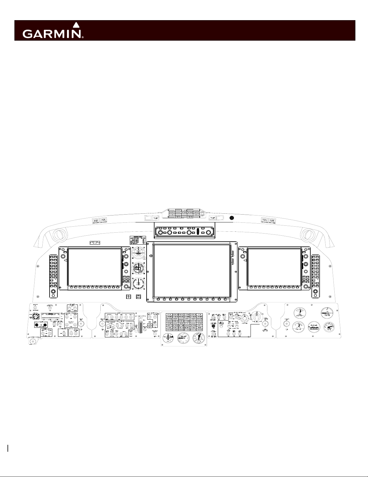
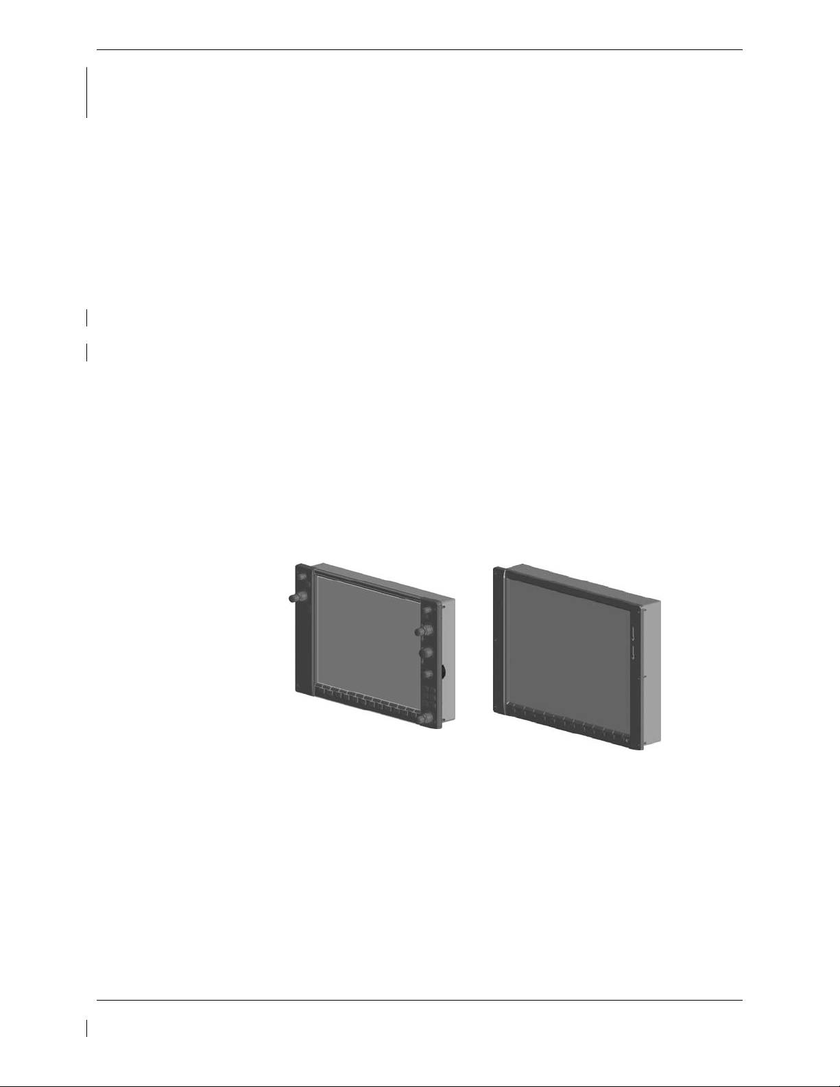
2.1.2 GDU 1040A PFD (2) & GDU 1500 MFD
Two Garmin GDU 1040A displays and one GDU 1500 display are installed in the King Air instrument
panel. The GDU 1040A units, 10.4 inch LCD displays with 1024x768 resolution, are configured as PFD
1 and PFD 2; the GDU 1500 unit, a 15 inch LCD display with 1024x768 resolution, is configured as a
MFD. All displays provide control and display of nearly all functions of the G1000 integrated cockpit
system. The PFD displays are located on either side of the MFD, with the stand-by instruments located
between the Pilot’s PFD (PFD 1) and the MFD. GMA 1347D Audio Panels are located outboard of each
PFD. Additionally, a GMC 710 AFCS Controller is located in the upper instrument panel, above the
MFD, and a GCU 477 is installed in the pedestal. The GCU 477 provides the control interface for the
MFD.
The GDU 1500 communicates with the GDU 1040A units, GDL 69A datalink, GWX68 or GWX70
weather radar, optional GSD41 data concentrator, optional GDL59 wi-fi datalink and optional GTS
820/850 or GTS Processor traffic through a high-speed data bus (HSDB) Ethernet connection. The GDU
1500 communicates with the GCU 477 via RS-232 digital interface.
The GDU 1040A units communicate with each other and the GIA 63W units through a high-speed data
bus (HSDB) Ethernet connection.
PFD 1 receives primary electrical power from No. 1 Triple Fed Bus and secondary electrical power from
Center Bus. PFD 2 receives electrical power from No. 3 Triple Fed Bus. Electrical power to the MFD is
provided by No. 2 Triple Fed Bus. The displays will power-up immediately with external or aircraft
power or battery operation.
All displays are installed in the King Air panel using ¼-turn fasteners. Three CDU cooling fans are also
installed behind the panel for PFD and MFD cooling.
Figure 2-1 Display Units
Page 2-2 G1000 / GFC 700 System Maintenance Manual - 300/B300 Series King Air
Revision 4 190-00716-01

2.1.3 GMA 1347D Audio Panel (2)
The Garmin GMA 1347D Audio Panel integrates NAV/COM digital audio, intercom system and marker
beacon controls. The 300/B300 installation includes two GMA 1347D panels. The GMA 1347D panels
provide control of all cockpit intercom/mic systems as well as NAV/COM/ILS audio. The units also
provide display reversion mode control through a large red button. Warning and alert audio received by
the GMA 1347Ds is processed by and received from the GIA 63W Integrated Avionics Units (IAUs).
Electrical power to GMA 1 is provided from No. 1 Triple Fed Bus. Electrical power to GMA 2 is
provided from Left Gen Avionics Bus. GMA 1 will be powered immediately with external or aircraft
power or battery operation. GMA 2 will operate after selecting Avionics Master on. The GMA 1347D
units interface with the existing marker beacon antenna, as well as existing mic and phone jacks and
oxygen mask mic.
Figure 2-2, Audio Panel
2.1.4 GMC 710 AFCS Control Unit
The dedicated AFCS controls on the GMC 710 allow crew control interface with the various GFC 700
autopilot / flight director functions. GMC 710 controls are discussed in detail in the G1000/King Air
300/B300 Series Cockpit Reference Guide. The GMC 710 is powered by No. 1 Triple Fed Bus.
Figure 2-3, AFCS Controller
G1000 / GFC 700 System Maintenance Manual - 300/B300 Series King Air Page 2-3
190-00716-01 Revision 4

2.1.5 GCU 477 FMS Control Unit
The GCU 477 functions as the primary control interface to the GDU 1500 MFD. The GCU 477 provides
alphanumeric, softkey, and flight planning function keys used to interface with the G1000; the MFD does
not possess any knobs or controls other than softkeys. The GCU 477 is powered by No. 3 Triple Fed
Bus. The GCU 477 also provides the crew with the added functionality of tuning their receivers via the
GCU as well as the PFD. Detailed instructions regarding the controls are discussed in the G1000 Cockpit
Reference Guide.
Figure 2-4, FMS Controller
2.1.6 Transponder (2)
The Garmin GTX 33( ) or GTX 3000 transponders communicates with the on-side GIA 63W through RS232 digital interface. This STC installation allows for installation of two GTX 33 non-diversity
transponders, two GTX 33D diversity transponders, or one of each type. This STC installation also
allows for installation of two GTX 3000 diversity transponders. Mixing between the GTX 33 and GTX
3000 transponsders is not permissible. Additionally, for TCAS II operations, the GTX 3000 transponder
communicates with the GTS Processor through ARINC 429 digital interfaces (transmit and receive). The
transponder units are mounted on the upper avionics equipment shelf in the tail section of the airplane.
Power is provided by the No. 1 GTX from Triple Fed Avionics Bus. The No. 2 GTX is powered from
Left Gen Avionics Bus. All GTX transponders (non-diversity and diversity) interface with a transponder
antenna mounted to the bottom of the fuselage. Each diversity transponder (GTX33D and GTX 3000)
interfaces to a transponder antenna mounted to the top of the fuselage.
GTX 33() GTX 3000
Figure 2-5, Transponder
Page 2-4 G1000 / GFC 700 System Maintenance Manual - 300/B300 Series King Air
Revision 4 190-00716-01

2.1.7 GIA 63W Integrated Avionics Unit (2)
Two Garmin GIA 63W Integrated Avionics Units (IAUs) contain the VHF COM/NAV receivers, WAAS
GPS receiver, Flight Director, and system integration microprocessors. The GIAs also serve as a
communication interface to all other G1000 LRUs in the system. Each GIA 63W communicates directly
with the on-side GDU 1040A display using a HSDB Ethernet connection. Both GIAs are located
remotely in the nose equipment bay.
GIA 1 receives primary electrical power from No. 1 Triple Fed Bus and a secondary electrical power
supply from Center Bus. GIA 2 receives electrical power from No. 3 Triple Fed Bus. The GIA 1’s
COMM power supply (COMM 1) is provided by No. 1 Triple Fed Bus. GIA 2’s COMM power supply
(COMM 2) is provided by Left Gen Avionics Bus. Therefore, both GIAs power-up immediately with
external or aircraft power or battery operation, with the exception of COMM 2 operation which will
become active after selection of Avionics Master on.
Both GIA 63Ws interface to the following equipment:
• Existing VOR/LOC/Glideslope Antenna System
• Existing VHF COM #1 & #2 Antennas
• GA 36 and GA 37 GPS/WAAS Antennas
• GMA 1347D, #1 & #2
• GEA 71, #1 & #2
• GDU 1040A, #1 & #2
• GSA 80
• GSA 9000
• GRS 77 or GRS 7800, #1 & #2
• Traffic System (if installed)
The GIA 63W #1 interfaces to the following additional equipment:
• GDC 7400 #1
• GTX 33( ) or GTX 3000 #1
• DME 42 (if installed)
• GSR 56 (if installed per stand-alone configuration)
The GIA 63W #2 interfaces to the following additional equipment:
• GDC 7400 #2
• GTX 33( ) or GTX 3000 #2
• ADF (if installed)
• Stormscope (if installed)
• Radar Altimeter (if installed)
Figure 2-6, GIA unit
G1000 / GFC 700 System Maintenance Manual - 300/B300 Series King Air Page 2-5
190-00716-01 Revision 4

2.1.8 GEA 71 Engine/Airframe Unit (2)
The Garmin GEA 71 Engine/Airframe Units provide engine/airframe data to the G1000 system. Data
received from transducers/sensors is processed and sent to GIA 63Ws (via RS-485 digital interface), and
subsequently to the GDU 1500 MFD. Engine parameters are normally displayed on the MFD. In the
event of MFD failure, the engine parameters can be displayed on PFD 1 and/or PFD 2 using display
reversion. The GEAs are located behind the instrument panel and is mounted in a vertical orientation.
Electrical power to GEA 1 is provided from No. 1 Triple Fed Bus and to GEA 2 from No. 2 Triple Fed
Bus. Both GEA units will power-up immediately with external or aircraft power or battery operation.
Each GEA interfaces to the following sensors for its onside engine:
• Oil Pressure Sensor
• Oil Temperature Sensor
• Fuel Flow Sensor (via onside Signal Conditioner)
• Turbine Speed Sensor (via onside Signal Conditioner)
• Propeller Speed Sensor(via onside Signal Conditioner)
• Torque Sensor
• Interstage Turbine Temperature (ITT) Sensor
Figure 2-7, GEA unit
Page 2-6 G1000 / GFC 700 System Maintenance Manual - 300/B300 Series King Air
Revision 4 190-00716-01

2.1.9 GDC 7400 Digital Air Data Computer (2)
The Garmin GDC 7400 computers compile information from the pitot/static system and various outside
air temperature (OAT) and awareness sensors and provide digital air data computations to the G1000
system. The GDC 7400 communicates with the GIA 63W, GDU 1040A, and GRS 77 using ARINC 429
digital interface. The unit is mounted behind the instrument panel. GDC 1 receives primary electrical
power from No. 1 Triple Fed Bus and a secondary power supply from Center Bus. GDC 2 receives
power from No. 3 Triple Fed Bus. GDC 1 and GDC 2 connect to existing pitot/static ports. Refer to
Figure 2-24 for a schematic of the aircraft’s pitot/static system and its connections to the G1000 STC
installed equipment.
IMPORTANT!
Aircraft modified by this STC are eligible to be approved for RVSM operation.
RVSM critical maintenance instructions contained in this document must be
followed in order to guarantee performance within RVSM specifications.
Figure 2-8, Air Data Computer
2.1.10 OAT Probe (2)
The Garmin GTP 59 OAT Probes provide the GDC 7400 with air temperature data. The OAT probes are
mounted to the bottom of the fuselage at F.S. 113.5.
Figure 2-9, OAT probe
G1000 / GFC 700 System Maintenance Manual - 300/B300 Series King Air Page 2-7
190-00716-01 Revision 4

2.1.11 Attitude & Heading Reference System (2)
The Garmin GRS 77 or GRS 7800 AHRS units provide attitude and heading information to the G1000
system. The units, mounted in the nose equipment bay, contain advanced tilt sensors, accelerometers,
and rate sensors. The unit interfaces with the Garmin Air Data Computers and GMU44 Magnetometer
and utilizes GPS signals from the GIA 63Ws. Actual attitude and heading information is sent using
ARINC 429 digital interface to both GDU 1040As and GIA 63Ws. The GRS interfaces with and
provides power to the GMU 44 Magnetometer. The GRS supplies attitude and heading information
directly to the PFDs, MFD, and GIAs. The #2 GRS AHRS units can provide heading data to an approved
third party TCAS II device through an ARINC 429 digital interface.
Additionally, the GRS 7800 AHRS provides heading with or without the aiding of the GMU 44
magnetometer. When operating without the aid of the magnetometer, the GRS 7800 is functionally
similar to that of a Directional Gyro.
GRS 1 receives primary electrical power from No. 1 Triple Fed Bus and a secondary power supply from
the Center Bus. GRS 2 receives electrical power from No. 3 Triple Fed Bus.
GRS 77 GRS 7800
Figure 2-10, AHRS
2.1.12 GMU 44 Magnetometer (2)
The GMU 44 provides horizontal and vertical magnetic field information to the GRS AHRS. This allows
heading to be calculated and provides assistance during AHRS alignment. The GMU 44 units are
mounted in the tailcone or in the horizontal stabilizer. The 011-00870-20 GMU 44 units may only be
installed in the horizontal stabilizer. The GMU 44 units were modified to account for low clearance
installations and have a 90-degree pig-tail harness versus the straight harness on the 011-08870-10 GMU
44 units. The units receive power directly from the GRS units and communicate with the GRS units via
RS-485 digital interface.
GMU 44 -00 & -10 Unit GMU 44 -20 Unit
Figure 2-11, Magnetometer
Page 2-8 G1000 / GFC 700 System Maintenance Manual - 300/B300 Series King Air
Revision 4 190-00716-01

2.1.13 GDL 69A Datalink
The GDL 69A provides the interface to the GWX 68 or GWX 70 weather radar and optional GDL59 wi-fi
datalink by acting as a communications hub between the MFD and GWX 68/GWX 70 and GDL 59 via
HSDB. The GDL 69A also provides XM Radio weather and music entertainment through means of a
dedicated satellite data link. The GDL 69A is mounted behind the instrument panel. Power to the GDL
69A is received from Right Gen Avionics Bus. The GDL 69A sends weather data through the HSDB bus
to the MFD, where the data link interface is controlled. Digital audio is sent directly to the GMA 1347D
Audio Panel.
Optional remote control (GRC 10) and remote control transceiver (GRT 10) may be interfaced with the
GDL 69A. Installation of the GRC 10 and GRT 10 is in accordance with Garmin STC SA01487SE or
other approved data. Refer to the approved Instructions for Continued Airworthiness information for
these units. It is recommended that GRT 10 be powered from the Entertainment Bus.
Figure 2-12, GDL 69A Datalink
2.1.14 GDL 59 Wi-Fi Datalink (optional)
The GDL 59 provides a POTS (plain old telephone service) phone interface and a high speed data link
between the aircraft systems and ground computers while the aircraft is on the ground using the IEEE
802.11g (“Wi-Fi”) protocol. The GDL 59 also provides the interface to an optional GSR 56 satellite
datalink, which adds airborne low speed data link and voice communication capability. The GDL 59 unit
interfaces to the Garmin Integrated Flight Deck via the GDL69A using HSDB. The GDL 59 is located on
the upper avionics equipment shelf in the tail section. The GDL 59 is powered from the Right Gen
Avionics Bus.
Figure 2-13, GDL 59 Wi-Fi Datalink
G1000 / GFC 700 System Maintenance Manual - 300/B300 Series King Air Page 2-9
190-00716-01 Revision 4

2.1.15 GSR 56 Satellite Receiver (optional)
The GSR 56 provides airborne low speed data link and voice communication capability to Garmin
Integrated Flight Deck installations. The GSR 56 contains a transceiver that operates on the Iridium
Satellite network. The GSR 56 interfaces directly to the GDL 59 via an RS-232 interface or may be
installed as a stand-alone unit with an interface to GIA #1. The GSR 56 is located on the
equipment shelf in the tail section
. The GSR 56 is powered from Right Gen Avionics Bus.
upper avionics
Figure 2-14, GSR 56 Satellite Receiver
2.1.16 GSD 41 Data Concentrator (optional)
The GSD 41 interfaces to various airframe discrete outputs to support third party systems such as Flight
Data Recorders. The GSD 41 is located on the avionics shelf in the tail area. The GSD 41 is powered
from No. 2 Triple Fed Bus.
Figure 2-15, GSD 41 Data Concentrator
Page 2-10 G1000 / GFC 700 System Maintenance Manual - 300/B300 Series King Air
Revision 4 190-00716-01

2.1.17 GTS 820/850 Traffic System (optional)
The GTS 820/850 is a traffic surveillance system that uses active interrogation of Mode S and Mode C
transponders to provide traffic advisories to the pilot. The GTS 820 is a TAS unit; the GTS 850 is a
TCAS I unit. The installation includes a top directional antenna (GA 58) paired with a GPA 65 power
amplifier / low noise amplifier (PA/LNA) unit and a bottom, unamplified GA 58 antenna. The GTS
820/850 is located in the nose avionics bay on the top, left shelf. The GPA 65 is located in the left
sidewall area, just in front of the most forward cabin window. The GTS 820/850 traffic system is
powered from Right Gen Avionics Bus.
Figure 2-16, GTS 820/850 Traffic System
2.1.18 GTS Traffic Processor
The GTS Traffic Processor is a microprocessor-based Line Replaceable Unit that uses active
interrogations of Mode S and Mode A/C transponders to provide Traffic Advisories and Resolution
Advisories (GTS 8000 only) to the pilot. When installed, the GTS Processor can be configured as TAS
(GTS 825), TCAS I (GTS 855), or TCAS II (GTS 8000). The GTS traffic processor is installed in the
nose avionics bay. The GTS interfaces to the GA58 traffic antennas which are mounted on the upper and
lower fuselage. The GTS traffic processor also interfaces with the GTX 3000 through ARINC 429 digital
data lines. The GTS traffic processor is powered from the Right Gen Avionics Bus.
Figure 2-17, GTS Traffic Processor
G1000 / GFC 700 System Maintenance Manual - 300/B300 Series King Air Page 2-11
190-00716-01 Revision 4

2.1.19 Weather Radar
The GWX 68 or optional GWX 70 Airborne Weather Radar provides weather radar data output to the
GDU 1500 MFD. The GWX is mounted forward of the forward bulkhead at F.S. 30. Power to the GWX
is received from Left Gen Avionics Bus. Data received from the GWX is routed through the GDL 69A
data link unit to the MFD via high-speed data bus (Ethernet).
Figure 2-18, Weather Radar
2.1.20 GSA 80 Servos and GSM 86 Servo Gearboxes (3)
The Garmin GFC 700 AFCS uses GSA 80 high torque servos to control aircraft pitch, pitch trim and roll.
The pitch trim variant of the GSA 80 is a high speed servo actuator. The GSA 80 contains a motorcontrol and monitor circuit board, as well as a solenoid and a brushless DC motor. The GSA 80 servo
receives serial RS-485 data packets from the GIA 63Ws. The roll servo is located in the forward cabin
lower fuselage near the wing front spar. The pitch and pitch trim servos are located in the tail. Power to
the servos is received from No. 2 Triple Fed Bus. All servos mount to Garmin GSM 86 Servo Gearboxes.
The GSM 86 is responsible for transferring the output torque of the GSA 80 servo actuators to the
mechanical flight control surface linkage.
Figure 2-19, GSA 80 / GSM 86
Page 2-12 G1000 / GFC 700 System Maintenance Manual - 300/B300 Series King Air
Revision 4 190-00716-01
 Loading...