

Garmin SA01535Wi-D Cockpit Reference Guide

®
G1000
Cockpit Reference Guide for the Beechcraft 200/B200 Series
Integrated Flight Deck


FLIGHT INSTRUMENTS
NAV/COM/TRANSPONDER/AUDIO PANEL
AUTOMATIC FLIGHT CONTROL SYSTEM
GPS NAVIGATION
FLIGHT PLANNING
PROCEDURES
HAZARD AVOIDANCE
ADDITIONAL FEATURES
ANNUNCIATIONS & ALERTS
APPENDIX
INDEX


Copyright © 2011, 2013 Garmin Ltd. or its subsidiaries. All rights reserved.
This manual reflects the operation of System Software version 0985.07 or later for the
Beechcraft 200 and B200. Some differences in operation may be observed when comparing
the information in this manual to earlier or later software versions.
Garmin International, Inc., 1200 East 151st Street, Olathe, Kansas 66062, U.S.A.
Tel: 913/397.8200 Fax: 913/397.8282
Garmin AT, Inc., 2345 Turner Road SE, Salem, OR 97302, U.S.A.
Tel: 503/391.3411 Fax 503/364.2138
Garmin (Europe) Ltd, Liberty House, Bulls Copse Road, Hounsdown Business Park,
Southampton, SO40 9RB, U.K.
Tel: 44/0870.8501241 Fax: 44/0870.8501251
Garmin Corporation, No. 68, Jangshu 2nd Road, Shijr, Taipei County, Taiwan
Tel: 886/02.2642.9199 Fax: 886/02.2642.9099
For after-hours emergency, aircraft on ground (AOG) technical support for Garmin panel mount
and integrated avionics systems, please contact Garmin’s AOG Hotline at 913.397.0836.
Web Site Address: www.garmin.com
Except as expressly provided herein, no part of this manual may be reproduced, copied,
transmitted, disseminated, downloaded or stored in any storage medium, for any purpose
without the express written permission of Garmin. Garmin hereby grants permission to
download a single copy of this manual and of any revision to this manual onto a hard drive or
other electronic storage medium to be viewed for personal use, provided that such electronic
or printed copy of this manual or revision must contain the complete text of this copyright
notice and provided further that any unauthorized commercial distribution of this manual or any
revision hereto is strictly prohibited.
Garmin® , G1000®, WATCH®, FliteCharts®, and SafeTaxi® are registered trademarks of Garmin
Ltd. or its subsidiaries. ESP™ is a trademark of Garmin Ltd. or its subsidiaries. These trademarks
may not be used without the express permission of Garmin.
NavData® is a registered trademark of Jeppesen, Inc.; SiriusXM™ is a trademark of SiriusXM™
Satellite Radio, Inc.
AOPA Membership Publications, Inc. and its related organizations (hereinafter collectively
“AOPA”) expressly disclaim all warranties, with respect to the AOPA information included in this
data, express or implied, including, but not limited to, the implied warranties of merchantability
and fitness for a particular purpose. The information is provided “as is” and AOPA does not
warrant or make any representations regarding its accuracy, reliability, or otherwise. Under

no circumstances including negligence, shall AOPA be liable for any incidental, special or
consequential damages that result from the use or inability to use the software or related
documentation, even if AOPA or an AOPA authorized representative has been advised of the
possibility of such damages. User agrees not to sue AOPA and, to the maximum extent allowed
by law, to release and hold harmless AOPA from any causes of action, claims or losses related
to any actual or alleged inaccuracies in the information. Some jurisdictions do not allow the
limitation or exclusion of implied warranties or liability for incidental or consequential damages
so the above limitations or exclusions may not apply to you.
AC-U-KWIK and its related organizations (hereafter collectively “AC-U-KWIK Organizations”)
expressly disclaim all warranties with respect to the AC-U-KWIK information included
in this data, express or implied, including, but not limited to, the implied warranties of
merchantability and fitness for a particular purpose. The information is provided “as is” and
AC-U-KWIK Organizations do not warrant or make any representations regarding its accuracy,
reliability, or otherwise. Licensee agrees not to sue AC-U-KWIK Organizations and, to the
maximum extent allowed by law, to release and hold harmless AC-U-KWIK Organizations
from any cause of action, claims or losses related to any actual or alleged inaccuracies in the
information arising out of Garmin’s use of the information in the datasets. Some jurisdictions
do not allow the limitation or exclusion of implied warranties or liability for incidental or
consequential damages so the above limitations or exclusions may not apply to licensee.
November, 2013 190-00929-04 Rev. A Printed in the U.S.A.
Warnings, Cautions & Notes
WARNING: Navigation and terrain separation must NOT be predicated upon
the use of the terrain avoidance feature. The terrain avoidance feature is NOT
intended to be used as a primary reference for terrain avoidance and does
not relieve the pilot from the responsibility of being aware of surroundings
during flight. The terrain avoidance feature is only to be used as an aid for
terrain avoidance. Terrain data is obtained from third party sources. Garmin
is not able to independently verify the accuracy of the terrain data.
WARNING: The displayed minimum safe altitudes (MSAs) are only advisory
in nature and should not be relied upon as the sole source of obstacle and
terrain avoidance information. Always refer to current aeronautical charts
for appropriate minimum clearance altitudes.
WARNING: The altitude calculated by G1000 GPS receivers is geometric
height above Mean Sea Level and could vary significantly from the altitude
displayed by pressure altimeters, such as the GDC 74B Air Data Computer,
or other altimeters in the aircraft. GPS altitude should never be used for
vertical navigation. Always use pressure altitude displayed by the G1000
PFD or other pressure altimeters in aircraft.
WARNING: Do not use outdated database information. Databases used in
the G1000 system must be updated regularly in order to ensure that the
information remains current. Pilots using any outdated database do so
entirely at their own risk.
WARNING: Do not use basemap (land and water data) information for
primary navigation. Basemap data is intended only to supplement other
approved navigation data sources and should be considered as an aid to
enhance situational awareness.
WARNING: Do not rely solely upon the display of traffic information for
collision avoidance maneuvering. The traffic display does not provide collision
avoidance resolution advisories and does not under any circumstances or
conditions relieve the pilot’s responsibility to see and avoid other aircraft.
190-00929-04 Rev. A
Garmin G1000 Cockpit Reference Guide for the Beechcraft 200/B200 Series
Warnings, Cautions & Notes
WARNING: Do not rely solely upon the display of traffic information to
accurately depict all of the traffic within range of the aircraft. Due to lack
of equipment, poor signal reception, and/or inaccurate information from
aircraft or ground stations, traffic may be present that is not represented on
the display.
WARNING: Do not use data link weather information for maneuvering in,
near or around areas of hazardous weather. Information contained within data
link weather products may not accurately depict current weather conditions.
WARNING: Do not use the indicated data link weather product age to
determine the age of the weather information shown by the data link weather
product. Due to time delays inherent in gathering and processing weather
data for data link transmission, the weather information shown by the data
link weather product may be significantly older than the indicated weather
product age.
WARNING: Do not rely on information from the lightning detection system
display as the sole basis for hazardous weather avoidance. Range limitations
and interference may cause the system to display inaccurate or incomplete
information. Refer to the documentation from the lightning detection system
manufacturer for detailed information about the system.
WARNING: The Garmin system, as installed in this aircraft, has a very
high degree of functional integrity. However, the pilot must recognize that
providing monitoring and/or self-test capability for all conceivable system
failures is not practical.
WARNING: Lamp(s) inside this product may contain mercury (HG) and must
be recycled or disposed of according to local, state, or federal laws. For
more information, refer to our website at www.garmin.com/aboutGarmin/
environment/disposal.jsp.
Garmin G1000 Cockpit Reference Guide for the Beechcraft 200/B200 Series
190-00929-04 Rev. A

Warnings, Cautions & Notes
WARNING: The United States government operates the Global Positioning
System and is solely responsible for its accuracy and maintenance. The GPS
system is subject to changes which could affect the accuracy and performance
of all GPS equipment. Portions of the Garmin G1000 utilize GPS as a
precision electronic NAVigation AID (NAVAID). Therefore, as with all NAVAIDs,
information presented by the G1000 can be misused or misinterpreted and,
therefore, become unsafe.
WARNING: To reduce the risk of unsafe operation, carefully review and
understand all aspects of the G1000 Pilot’s Guide documentation and the
G1000 Integrated Avionics System in the Airplane Flight Manual. Thoroughly
practice basic operation prior to actual use. During flight operations, carefully
compare indications from the G1000 to all available navigation sources,
including the information from other NAVAIDs, visual sightings, charts, etc.
For safety purposes, always resolve any discrepancies before continuing
navigation.
WARNING: For safety reasons, G1000 operational procedures must be learned
on the ground.
WARNING: Do not use the system to attempt to penetrate a thunderstorm.
The illustrations in this guide are only examples. Both the FAA Advisory
Circular, Subject: Thunderstorms, and the Aeronautical Information Manual
(AIM) recommend avoiding any thunderstorm identified as severe of giving
intense radar echo by at least 20 miles.
WARNING: Because of variation in the earth’s magnetic field, operating the
system within the following areas could result in loss of reliable attitude and
heading indications (GRS 77 installations only). North of 72° North latitude
at all longitudes. South of 70° South latitude at all longitudes. North of 65°
North latitude between longitude 75° W and 120° W. (Northern Canada).
North of 70° North latitude between longitude 70° W and 128° W. (Northern
Canada). North of 70° North latitude between longitude 85° E and 114° E.
(Northern Russia). South of 55° South latitude between longitude 120° E
and 165° E. (Region south of Australia and New Zealand).
190-00929-04 Rev. A
Garmin G1000 Cockpit Reference Guide for the Beechcraft 200/B200 Series
Warnings, Cautions & Notes
WARNING: Do not use GPS to navigate to any active waypoint identified as
a ‘NON WGS84 WPT’ by a system message. ‘NON WGS84 WPT’ waypoints are
derived from an unknown map reference datum that may be incompatible
with the map reference datum used by GPS (known as WGS84) and may be
positioned in error as displayed.
CAUTION: The PFD and MFD displays use a lens coated with a special
anti-reflective coating that is very sensitive to skin oils, waxes, and abrasive
cleaners. CLEANERS CONTAINING AMMONIA WILL HARM THE ANTIREFLECTIVE COATING. It is very important to clean the lens using a clean,
lint-free cloth and an eyeglass lens cleaner that is specified as safe for antireflective coatings.
CAUTION: The Garmin G1000 does not contain any user-serviceable parts.
Repairs should only be made by an authorized Garmin service center.
Unauthorized repairs or modifications could void both the warranty and the
pilot’s authority to operate this device under FAA/FCC regulations.
NOTE: All visual depictions contained within this document, including screen
images of the G1000 panel and displays, are subject to change and may not
reflect the most current G1000 system and aviation databases. Depictions
of equipment may differ slightly from the actual equipment.
NOTE: This device complies with part 15 of the FCC Rules. Operation is
subject to the following two conditions: (1) this device may not cause harmful
interference, and (2) this device must accept any interference received,
including interference that may cause undesired operation.
NOTE: This product, its packaging, and its components contain chemicals
known to the State of California to cause cancer, birth defects, or reproductive
harm. This notice is being provided in accordance with California’s Proposition
65. If you have any questions or would like additional information, please
refer to our web site at www.garmin.com/prop65.
NOTE: Interference from GPS repeaters operating inside nearby hangars can
cause an intermittent loss of attitude and heading displays while the aircraft
is on the ground. Moving the aircraft more than 100 yards away from the
source of the interference should alleviate the condition.
Garmin G1000 Cockpit Reference Guide for the Beechcraft 200/B200 Series
190-00929-04 Rev. A

Warnings, Cautions & Notes
NOTE: Use of polarized eyewear may cause the flight displays to appear dim
or blank.
NOTE: When operating the G1000 in DG Free Mode (GRS 7800 installations
only), the heading information used by some system components (e.g. GTS
8000, AFCS, and GWX) will be different from the heading displayed on the
GDU by an amount equal to the difference between the current Magnetic
Field Variation Database (MV DB) value, and the MV DB value when DG Free
Mode was activated. Due to the convergence of isogonic lines, this condition
is most noticeable at or near the North and South poles.
NOTE: System navigation utilities may not reliably calculate range and
bearing information when the aircraft is operating north of 80° North latitude
or south of 80° South latitude. This may result in the system displaying small
gaps in racetrack holding pattern depictions (GRS 7800 installations only).
NOTE: The Terrain Awareness and Warning System (TAWS) may not operate
reliably north of 89º North latitude and south of 89º South latitude. This is
due to limitations present within the Terrain database and the system’s ability
to process the data representing the affected areas (GRS 7800 installations
only).
NOTE: The purpose of this Cockpit Reference Guide is to provide the pilot
a resource with which to find operating instructions on the major features
of the G1000 system more easily. It is not intended to be a comprehensive
operating guide. Complete operating procedures for the system are found
in the G1000 Pilot’s Guide for this aircraft.
190-00929-04 Rev. A
Garmin G1000 Cockpit Reference Guide for the Beechcraft 200/B200 Series

Warnings, Cautions & Notes
Blank Page
Garmin G1000 Cockpit Reference Guide for the Beechcraft 200/B200 Series
190-00929-04 Rev. A

Record of Revisions
Part Number Change Summary
190-00929-00 Initial release
190-00929-01 Added Synthetic Vision System
Added TAWS-A
Added AOPA Airport Directory
Added dual navigation database capability
Added database synchronization
Added other GDU 10.00 parameters
190-00929-02 Added GDU 11.12 changes
Added GTS 820/850
Added Electronic Stabilization & Protection
Iridium Telephone and Data Link
Added Worldwide Weather
190-00929-03 Added other GDU 12.01 parameters
Added METAR and WX LGND softkeys
Updated XM weather product symbols
Updated Iridium registration procedure
Updated SiriusXM product references
190-00929-04 Added GDU 13.06 parameters
Added GRS 7800, GTS 8000, GTX 3000, GRA 5500
Added Pilot Profiles
Added Temperature Compensated Altitude
Added User-defined Holds
Added TCAS II
Removed Reports Page
Added DG Mode
Changed GFDS to Connext
Revision Date of Revision Affected Pages Description
A November, 2013 All Production release
190-00929-04 Rev. A RR-1
Garmin G1000 Cockpit Reference Guide for the Beechcraft 200/B200 Series

Record of Revisions
Blank Page
RR-2
Garmin G1000 Cockpit Reference Guide for the Beechcraft 200/B200 Series
190-00929-04 Rev. A

Table of Contents
FLIGHT INSTRUMENTS ................................................................................................................ 1
Selecting the Altimeter Barometric Pressure Setting ...................................................... 1
Selecting Standard Barometric Pressure (29.92 in Hg) ....................................................1
Change Altimeter Barometric Pressure Setting Units ...................................................... 1
Synchronizing the Altimeter Barometric Pressure Settings ........................................... 1
Synchronize CDI......................................................................................................................... 1
Selecting DG Mode (GRS 7800 Installations Only): ........................................................... 2
Change Navigation Sources ................................................................................................... 2
Enable/Disable OBS Mode While Navigating with GPS .................................................... 2
Generic Timer ............................................................................................................................. 3
Configure Vspeed Bugs Individually .....................................................................................3
Turn Vspeed Bugs On or Off by Category ............................................................................ 3
Set Barometric/Radar Altimeter Minimum Descent Altitude ......................................... 4
Testing the Radar Altimeter ................................................................................................... 4
Displaying Wind Data .............................................................................................................. 4
NAV/COM/TRANSPONDER/AUDIO PANEL .........................................................................5
ADF Tuning (Optional) .............................................................................................................. 5
DME Tuning.................................................................................................................................5
Enter a Transponder Code....................................................................................................... 5
Selecting a COM Radio ............................................................................................................ 5
Selecting a NAV Radio ............................................................................................................. 6
NAV/COM Tuning ....................................................................................................................... 6
Intercom ...................................................................................................................................... 6
Passenger Address (PA) System ............................................................................................. 7
Clearance Recorder and Player ............................................................................................. 7
AUTOMATIC FLIGHT CONTROL SYSTEM ............................................................................ 9
Flight Director Activation ....................................................................................................... 9
Vertical Modes .........................................................................................................................10
Lateral Modes .......................................................................................................................... 11
Suspected Autopilot Malfunction ....................................................................................... 12
Overpowering Autopilot Servos ......................................................................................... 12
GPS NAVIGATION ........................................................................................................................ 13
Direct-to Navigation .............................................................................................................. 13
Activate a Stored Flight Plan ............................................................................................... 14
Activate a Flight Plan Leg ..................................................................................................... 14
Stop Navigating a Flight Plan .............................................................................................. 15
Vertical Navigation (VNAV)................................................................................................... 15
190-00929-04 Rev. A i
Garmin G1000 Cockpit Reference Guide for the Beechcraft 200/B200 Series

Table of Contents
FLIGHT PLANNING ...................................................................................................................... 19
Weight Planning ...................................................................................................................... 19
Trip Planning ............................................................................................................................ 19
Create a User Waypoint Defined by Latitude & Longitude ........................................... 21
Create a User Waypoint Defined by Radials from Other Waypoints ........................... 22
Create a User Waypoint Defined by a Radial & Distance from Another Waypoint ..24
Delete a User Waypoint ......................................................................................................... 25
Create a Flight Plan ................................................................................................................ 26
Import a Flight Plan from an SD Card ................................................................................ 27
Insert a Waypoint in the Active Flight Plan ...................................................................... 27
Enter an Airway in a Flight Plan .......................................................................................... 28
User-Defined Holding Patterns ............................................................................................ 29
Invert An Active Flight Plan .................................................................................................. 31
Remove a Departure, Arrival, Appr, or Airway from a Flight Plan .............................. 31
Store a Flight Plan .................................................................................................................. 32
Edit a Stored Flight Plan ....................................................................................................... 32
Delete a Waypoint from the Flight Plan ............................................................................ 32
Invert and Activate a Stored Flight Plan ........................................................................... 33
Copy a Flight Plan ................................................................................................................... 33
Delete a Flight Plan ................................................................................................................ 33
Graphical Flight Plan Creation ............................................................................................. 34
Export a Flight Plan to an SD Card ..................................................................................... 34
PROCEDURES ................................................................................................................................. 35
Load and Activate a Departure Procedure ....................................................................... 35
Activate A Departure Leg ..................................................................................................... 35
Load An Arrival Procedure .................................................................................................... 35
Activate An Arrival Leg ......................................................................................................... 36
Load and/or Activate an Approach Procedure ................................................................. 36
Activate An Approach in the Active Flight Plan ............................................................... 37
Activate a Vector to Final Approach Fix ............................................................................ 37
Activate A Missed Approach in the Active Flight Plan ................................................... 38
Temperature Compensated Altitude .................................................................................. 38
HAZARD AVOIDANCE ................................................................................................................ 41
Customizing the Hazard Displays on the Navigation Map ............................................ 41
STORMSCOPE® (Optional) ..................................................................................................... 41
SiriusXM Satellite Weather (Optional) ...............................................................................43
Connext Weather (Optional) ................................................................................................ 46
Airborne Color Weather Radar ............................................................................................ 58
Traffic Avoidance Systems .................................................................................................... 61
Traffic Collision Avoidance System (TCAS II) (Optional) ................................................ 63
Terrain Awareness & Warning System ............................................................................... 65
ii
Garmin G1000 Cockpit Reference Guide for the Beechcraft 200/B200 Series
190-00929-04 Rev. A

Table of Contents
ADDITIONAL FEATURES ........................................................................................................... 69
Synthetic Vision ....................................................................................................................... 69
Terminal Procedure Charts ................................................................................................... 70
Airport Directory .................................................................................................................... 72
Satellite Telephone and Data Link Services ..................................................................... 73
WI-FI Connections ................................................................................................................... 86
SiriusXM™ Radio Entertainment .......................................................................................... 89
Pilot Profiles............................................................................................................................. 91
Electronic Stability & Protection (ESP™) .......................................................................... 94
ANNUNCIATIONS & ALERTS ................................................................................................... 97
WARNING Annunciation ........................................................................................................ 97
Advisory Annunciations......................................................................................................... 97
Message Advisory Alerts ....................................................................................................... 97
Comparator Annunciations ................................................................................................... 98
Reversionary Sensor Annunciations ................................................................................... 98
AFCS Alerts ............................................................................................................................... 99
TAWS-A Alerts ........................................................................................................................ 100
TAWS-B Alerts ........................................................................................................................ 103
Additional Voice Alerts ........................................................................................................ 106
MFD & PFD Message Advisories ........................................................................................ 107
Database Message Advisories ........................................................................................... 109
GMA 1347D Message Advisories ....................................................................................... 113
GIA 63W Message Advisories ............................................................................................. 113
GSD 41 Message Advisories (Optional) ............................................................................ 117
GEA 71 Message Advisories ................................................................................................ 117
GTX 33/33D/33ES/3000 Message Advisories .................................................................... 118
GRS 77/7800 Message Advisories ...................................................................................... 119
GMU 44 Message Advisories .............................................................................................. 121
GDL 59 Message Advisories ................................................................................................ 121
GSR 56 Message Advisories ................................................................................................ 122
GDL 69A Message Advisories ............................................................................................. 122
GWX 68/70 Message Advisories ......................................................................................... 122
GDC 74B/7400 Message Advisories ................................................................................... 123
GCU 477 Message Advisories ............................................................................................. 123
GMC 710 Message Advisories ............................................................................................ 124
GTS 820/825/850/855/8000 Message Advisories ............................................................. 124
GRA 5500 Message Advisories ........................................................................................... 124
Miscellaneous Message Advisories ................................................................................... 125
Flight Plan Import/Export Messages ................................................................................ 130
Pilot Profile Import/Export Messages .............................................................................. 131
190-00929-04 Rev. A iii
Garmin G1000 Cockpit Reference Guide for the Beechcraft 200/B200 Series

Table of Contents
APPENDIX ..................................................................................................................................... 133
PFD Softkey Map .................................................................................................................. 133
MFD Navigation Page Softkey Map ................................................................................. 142
Loading Updated Databases .............................................................................................. 144
INDEX .........................................................................................................................................Index-1
iv
Garmin G1000 Cockpit Reference Guide for the Beechcraft 200/B200 Series
190-00929-04 Rev. A

Flight Instruments
FLIGHT INSTRUMENTS
SELECTING THE ALTIMETER BAROMETRIC PRESSURE SETTING
Turn the BARO Knob to select the desired setting.
SELECTING STANDARD BAROMETRIC PRESSURE (29.92 IN HG)
1)
Press the PFD Softkey.
2)
Press the STD BARO Softkey to set standard barometric pressure.
CHANGE ALTIMETER BAROMETRIC PRESSURE SETTING UNITS
1)
Press the PFD Softkey to display the second-level softkeys.
2)
Press the ALT UNIT Softkey.
3)
Press the IN Softkey to display the barometric pressure setting in inches of
mercury (in Hg).
Or
:
Press the HPA Softkey to display the barometric pressure setting in
hectopascals.
4)
Press the BACK Softkey to return to the top-level softkeys.
Instruments
Flight
XPDR/Audio AFCS GPS Nav
Nav/Com/
Planning Procedures
Flight
Avoidance
Hazard
SYNCHRONIZING THE ALTIMETER BAROMETRIC PRESSURE SETTINGS
1)
Select the AUX-SYSTEM SETUP Page on the MFD.
2)
Press the FMS Knob to activate the cursor.
3)
Turn the large FMS Knob to highlight BARO in SYNCHRONIZATION
Window.
4)
Turn the
small
FMS Knob clockwise to ON or counterclockwise to OFF.
SYNCHRONIZE CDI
1)
Select the AUX-SYSTEM SETUP Page on the MFD.
2)
Press the FMS Knob to activate the cursor.
3)
Turn the large FMS Knob to highlight CDI in SYNCHRONIZATION Window.
4)
Turn the
190-00929-04 Rev. A 1
small
FMS Knob clockwise to ON or counterclockwise to OFF.
Garmin G1000 Cockpit Reference Guide for the Beechcraft 200/B200 Series
Additional
Features Annun/Alerts Appendix Index

Flight Instruments
SELECTING DG MODE (GRS 7800 INSTALLATIONS ONLY):
Flight
Instruments
NOTE: When operating the G1000 in DG Free Mode (GRS 7800 installations
only), the heading information used by some system components (e.g. GTS
Nav/Com/
XPDR/AudioAFCSGPS Nav
Flight
PlanningProcedures
8000, AFCS, and GWX) will be different from the heading displayed on the
GDU by an amount equal to the difference between the current Magnetic
Field Variation Database (MV DB) value, and the MV DB value when DG Free
Mode was activated. Due to the convergence of isogonic lines, this condition
is most noticeable at or near the North and South poles.
1)
Press the PFD Softkey.
2)
Press the HDG MODE Softkey.
3)
Press the DG FREE Softkey to activate DG mode. Press the DG SLAVE
Softkey to deactivate DG mode.
•
Pressing the HDG- or HDG+ softkey to slew the heading
counterclockwise or clockwise.
•
Pressing the HDG SYNC softkey to synchronize the heading to the
current selected heading.
•
Pressing the TRACK SYNC softkey to synchronize the heading to the
current track.
CHANGE NAVIGATION SOURCES
Hazard
Avoidance
1)
Press the CDI Softkey to change from GPS to VOR1 or LOC1. This changes
the NAV1 standby frequency in the upper left corner of the PFD to light
blue, indicating this is the frequency selected for tuning.
FeaturesAnnun/AlertsAppendixIndex
Additional
2)
Press the CDI Softkey again to change from VOR1 or LOC1 to VOR2 or
LOC2. This changes the NAV2 standby frequency in the upper left corner of
the PFD to light blue, indicating this is the frequency selected for tuning.
3)
Press the CDI Softkey a third time to return to GPS.
ENABLE/DISABLE OBS MODE WHILE NAVIGATING WITH GPS
1)
Press the OBS Softkey to select OBS Mode.
2)
Turn a CRS Knob to select the desired course to/from the waypoint. Press a
CRS Knob to synchronize the Selected Course with the bearing to the next
waypoint.
3)
Press the OBS Softkey again to disable OBS Mode.
2
Garmin G1000 Cockpit Reference Guide for the Beechcraft 200/B200 Series
190-00929-04 Rev. A

Flight Instruments
GENERIC TIMER
1)
Press the TMR/REF Softkey, then turn the large FMS Knob to select the
time field (hh/mm/ss). Turn the FMS Knobs to set the desired time, then
press the ENT Key. The UP/DOWN field is now highlighted.
2)
Turn the small FMS Knob to display the UP/DOWN window. Turn the FMS
Knob to select ‘UP’ or ‘DOWN’, then press the ENT Key. ‘START?’ is now
highlighted.
3)
Press the ENT Key to START, STOP, or RESET the timer (if the timer is
counting DOWN, it will start counting UP after reaching zero). Press the
CLR Key or the TMR/REF Softkey to remove the window.
CONFIGURE VSPEED BUGS INDIVIDUALLY
1)
Press the TMR/REF Softkey.
2)
Turn the
3)
Use the small FMS Knob to change the Vspeed in 1-kt increments (when a
speed has been changed from a default value, an asterisk appears next to
the speed).
4)
Press the ENT Key or turn the large FMS Knob to highlight the ON/OFF
field
5)
Turn the
6)
To remove the window, press the CLR Key or the TMR/REF Softkey.
large
FMS Knob to highlight the desired Vspeed.
small
FMS Knob clockwise to ON or counterclockwise to OFF.
Instruments
Flight
XPDR/Audio AFCS GPS Nav
Nav/Com/
Planning Procedures
Flight
Avoidance
Hazard
TURN VSPEED BUGS ON OR OFF BY CATEGORY
1)
Press the TMR/REF Softkey.
2)
Press the MENU Key.
3)
Turn the FMS Knob to highlight the desired option.
4)
Press the ENT Key. Press the TMR/REF Softkey to remove the window.
190-00929-04 Rev. A 3
Garmin G1000 Cockpit Reference Guide for the Beechcraft 200/B200 Series
Additional
Features Annun/Alerts Appendix Index

Flight Instruments
SET BAROMETRIC/RADAR ALTIMETER MINIMUM DESCENT ALTITUDE
Flight
Instruments
1)
Press the
2)
Turn the large FMS Knob to highlight the Minimums field.
3)
Nav/Com/
XPDR/AudioAFCSGPS Nav
Turn the small FMS Knob to select BARO, TEMP COMP, or RAD ALT. OFF
is selected by default. Press the ENT Key or turn the large FMS Knob to
highlight the next field.
4)
Use the small FMS Knob to enter the desired altitude (from zero to 16,000
feet for BARO, or from zero to 2,500 for RAD ALT).
5)
If TEMP COMP was selected, press the ENT Key or turn the large FMS
Knob to highlight the next field and then enter the destination airport
temperature (-59˚C to 59˚C). The temperature compensated altitude
minimum is displayed below the previously enter minimum altitude value.
6)
To remove the window, press the
Flight
PlanningProcedures
TESTING THE RADAR ALTIMETER
1)
Select the AUX-SYSTEM STATUS Page on the MFD.
2)
Select the RA TEST Softkey. ‘RA TEST’ is displayed to the left of the Radar
Altitude window. The Radar Altitude window displays 50 feet, indicating a
properly functioning system.
3)
Hazard
Avoidance
Selecting the RA TEST Softkey again, or exiting the System Status Page
cancels the test.
TMR/REF
Softkey.
CLR
Key or the
TMR/REF
Softkey.
DISPLAYING WIND DATA
FeaturesAnnun/AlertsAppendixIndex
Additional
1)
Press the PFD Softkey.
2)
Press the WIND Softkey to display wind data below the Selected Heading.
3)
Press one of the OPTN softkeys to change how wind data is displayed.
4)
To remove the Wind Data Window, press the OFF Softkey.
4
Garmin G1000 Cockpit Reference Guide for the Beechcraft 200/B200 Series
190-00929-04 Rev. A

Nav/Com/XPDR/Audio Panel
NAV/COM/TRANSPONDER/AUDIO PANEL
Instruments
Flight
ADF TUNING (OPTIONAL)
Tune the ADF using the remote ADF control head.
DME TUNING
1)
Press the DME Softkey.
2)
Turn the large FMS to select the DME source field.
3)
Turn the small FMS Knob to select the desired Nav radio.
4)
Press the ENT Key to complete the selection.
ENTER A TRANSPONDER CODE
1)
Press the XPDR Softkey to display the transponder mode selection softkeys.
2)
Press the XPDR1 or XPDR2 Softkey to select the active transponder.
3)
Press the CODE Softkey to display the transponder code selection softkeys,
for digit entry.
4)
Press the digit softkeys to enter the code in the code field. When entering
the code, the next key in sequence must be pressed within 10 seconds, or
the entry is cancelled and restored to the previous code. Five seconds after
the fourth digit has been entered, the transponder code becomes active.
SELECTING A COM RADIO
XPDR/Audio AFCS GPS Nav
Nav/Com/
Planning Procedures
Flight
Avoidance
Hazard
Additional
Features Annun/Alerts Appendix Index
Transmit/Receive
Press the COM1 MIC, COM2 MIC
, or
COM3 MIC Key (optional COM, if
installed) on the audio panel.
Receive Only
Press the COM1, COM2
audio panel.
190-00929-04 Rev. A 5
Garmin G1000 Cockpit Reference Guide for the Beechcraft 200/B200 Series
, or
COM3 Key (optional COM, if installed) on the

Nav/Com/XPDR/Audio Panel
SELECTING A NAV RADIO
Flight
1)
Instruments
To begin navigating using a navigation radio, press the CDI Softkey on the
PFD to select VOR1/LOC1 (NAV1) or VOR2/LOC2 (NAV2).
2)
Press the NAV1, NAV2, DME, or ADF Key on the audio panel to select or
Nav/Com/
XPDR/AudioAFCSGPS Nav
deselect the navigation radio audio source. All radio keys can be selected
individually or together.
NAV/COM TUNING
1)
Press the small tuning knob to select the desired radio for tuning. A light
blue box highlights the radio frequency to be tuned.
2)
Turn the respective tuning knobs to enter the desired frequency into the
standby frequency field. The large knob enters MHz and the small knob
enters kHz.
3)
Flight
PlanningProcedures
Press the Frequency Transfer Key to place the frequency into the active
frequency field.
INTERCOM
Pressing the INTR COM Key on either Audio Panel selects and deselects the
intercom on both Audio Panels. The annunciator is lit when the intercom is active.
The intercom connects the pilot and copilot together. Either the pilot or copilot may
select or deselect the intercom.
Hazard
Avoidance
The CABIN Key initiates two way communication between the pilot or copilot and
the passengers in the cabin. The annunciator is lit when the cabin intercom is active
on either Audio Panel.
FeaturesAnnun/AlertsAppendixIndex
Additional
The MAN SQ Key allows either automatic or manual control of the intercom
squelch setting. Pressing the MAN SQ Key enables manual squelch control, indicated
by the MAN SQ annunciator.
During manual squelch operation, pressing the ICS Knob switches between volume
and squelch adjustment, lighting the associated annunciator beneath the knob. When
the MAN SQ annunciator is lit, the ICS Knob controls both volume and squelch. When
the MAN SQ annunciator is extinguished, the ICS Knob controls only volume.
6
Garmin G1000 Cockpit Reference Guide for the Beechcraft 200/B200 Series
190-00929-04 Rev. A

Nav/Com/XPDR/Audio Panel
PASSENGER ADDRESS (PA) SYSTEM
Instruments
Flight
A passenger address system is provided by pressing the PA Key to deliver messages
to the passengers. The message is heard by the other pilot on the headset only if the
PA Key is enabled on both audio panels. PA messages are one way from the flight deck
XPDR/Audio AFCS GPS Nav
Nav/Com/
to the passengers.
CLEARANCE RECORDER AND PLAYER
NOTE: Pressing the play key on the pilot’s Audio Panel plays recorded audio
to the Pilot. Pressing the play key on the Copilot’s Audio Panel plays recorded
audio to the Copilot.
Recorded COM audio is stored in separate memory blocks. Once 2.5 minutes
of recording time have been reached, the recorder begins recording over the stored
Planning Procedures
Flight
memory blocks, starting from the oldest block.
The PLAY Key controls the play function. The PLAY annunciator is illuminated to
indicate when play is in progress. The PLAY annunciator extinguishes after playback
is finished.
Pressing the PLAY Key once plays the latest recorded memory block and then
returns to normal operation. Pressing the PLAY Key again during play of a memory
Avoidance
block stops play. If a COM input signal is detected during play of a recorded memory
Hazard
block, play is halted.
Pressing the PLAY Key twice within one-half second while audio is playing plays
the previous block of recorded audio. Each subsequent two presses of the PLAY Key
Additional
Features Annun/Alerts Appendix Index
within one-half second backtracks through the recorded memory blocks to reach and
play any recorded block.
190-00929-04 Rev. A 7
Garmin G1000 Cockpit Reference Guide for the Beechcraft 200/B200 Series

Nav/Com/XPDR/Audio Panel
Flight
Instruments
Nav/Com/
XPDR/AudioAFCSGPS Nav
Flight
PlanningProcedures
Blank Page
Hazard
Avoidance
FeaturesAnnun/AlertsAppendixIndex
Additional
8
Garmin G1000 Cockpit Reference Guide for the Beechcraft 200/B200 Series
190-00929-04 Rev. A
AFCS
AUTOMATIC FLIGHT CONTROL SYSTEM
NOTE: If sensor information (other than attitude) required for a flight director
mode becomes invalid or unavailable, the flight director automatically reverts
to the default mode for that axis.
NOTE: If the attitude information required for the default flight director modes
becomes invalid or unavailable, the autopilot automatically disengages.
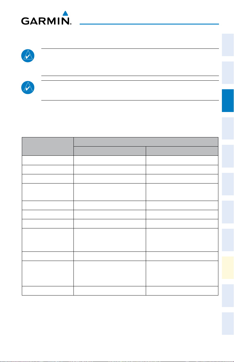
FLIGHT DIRECTOR ACTIVATION
An initial press of a key listed in the following table (when the flight director is not
active) activates the pilot-side flight director in the listed modes.
Instruments
Flight
XPDR/Audio AFCS GPS Nav
Nav/Com/
Control Pressed
Lateral Vertical
Modes Selected
FD Key Roll Hold (default) ROL Pitch Hold (default) PIT
AP Key Roll Hold (default) ROL Pitch Hold (default) PIT
CWS Button Roll Hold (default) ROL Pitch Hold (default) PIT
GA Switch
Takeoff (on ground)
Go Around (in air)
TO
GA
Takeoff (on ground)
Go Around (in air)
TO
GA
ALT Key Roll Hold (default) ROL Altitude Hold A LT
VS Key Roll Hold (default) ROL Vertical Speed VS
VNV Key Roll Hold (default) ROL Vertical Path Tracking* VPTH
GPS
NAV Key Navigation**
VOR
Pitch Hold (default) PIT
LOC
BC Key Backcourse*** BC Pitch Hold (default) PIT
APR Key Approach**
GPS
VAPP
LOC
Pitch Hold (default)
Glidepath
Glideslope
PIT
GP
GS
HDG Key Heading Select HDG Pitch Hold (default) PIT
*Valid VNV flight plan must be entered before VNV Key press activates flight director.
**The selected navigation receiver must have a valid VOR or LOC signal or active GPS course before
NAV
or
APR
Key press activates flight director.
***The selected navigation receiver must have a valid LOC signal before BC Key press activates flight
director.
Planning Procedures
Flight
Avoidance
Hazard
Additional
Features Annun/Alerts Appendix Index
190-00929-04 Rev. A 9
Garmin G1000 Cockpit Reference Guide for the Beechcraft 200/B200 Series

AFCS
VERTICAL MODES
Flight
Vertical Mode Description Control Annunciation
Instruments
Holds the current aircraft pitch attitude; may
Pitch Hold
Nav/Com/
XPDR/AudioAFCSGPS Nav
Selected Altitude
Armed
Altitude Hold Holds the current Altitude Reference ALT Key ALT nnnnn fT
Vertical Speed
Flight Level Change,
IAS Hold
Flight Level Change,
Flight
Mach Hold
PlanningProcedures
VNAV Captures and tracks the VNAV flight path VNV Key VPTH
VNAV Target
Altitude Armed
Glidepath
Hazard
Avoidance
Glideslope
Takeoff (on ground)
FeaturesAnnun/AlertsAppendixIndex
Additional
Go Around (in air)
Level Commands 0° pitch attitude
* ALTS armed automatically when PIT, VS, FLC, TO, or GA active, and under VPTH when Selected Altitude is to be
captured instead of VNAV Target Altitude
** ALTV armed automatically under VPTH when VNAV Target Altitude is to be captured instead of Selected Altitude
be used to climb/descend to the Selected
(default) PIT
Altitude
AFCS armed to capture the altitude displayed in
the Selected Altitude window
Maintains the current aircraft vertical speed;
may be used to climb/descend to the Selected
Altitude
Maintains the current aircraft airspeed (in
IAS or Mach) while the aircraft is climbing/
descending to the Selected Altitude. Press
FLC Key
the SPD Key to switch between IAS and
MACH.
AFCS armed to capture the altitude
displayed in the VNAV Target Altitude
window
Captures and tracks the SBAS glidepath on
approach
Captures and tracks the ILS glideslope on
APR Key
approach
Disengages the autopilot and commands a
constant pitch angle and wings level in the
air on the ground in preparation for takeoff
Disengages the autopilot and commands a
constant pitch attitude and wings level in
the air
Activated
the ESP
function
* ALTS
VS Key VS nnnn fpm
FLC nnn kT
FLC M .nnn
** ALTV
GA
Switch
only by
GP
GS
TO
GA
LVL
10
Garmin G1000 Cockpit Reference Guide for the Beechcraft 200/B200 Series
190-00929-04 Rev. A

AFCS
LATERAL MODES
Instruments
Flight
Lateral Mode Description Control Annunciation
Roll Hold
Holds current aircraft roll attitude
or rolls wings level, depending on
(default) ROL
XPDR/Audio AFCS GPS Nav
Nav/Com/
commanded bank angle
Low Bank
Heading Select
Navigation, GPS Arm/
Capture/Track
Navigation, VOR Enroute
Arm/Capture/Track
Navigation, LOC Arm/
Capture/Track
Limits maximum commanded roll
angle
Captures and tracks Selected
Heading
Captures and tracks selected
navigation source (GPS, VOR, LOC)
BANK
Key
*
HDG Key HDG
GPS
NAV Key
VOR
LOC
Planning Procedures
Flight
(No Glideslope)
Backcourse Arm/Capture/
Track
Approach, GPS Arm/Capture/
Track
Approach, VOR Arm/Capture/
Track
Approach, ILS Arm/Capture/
Track
(Glideslope Mode
Captures and tracks a localizer
signal for backcourse approaches
Captures and tracks selected
navigation source (GPS, VOR, LOC)
BC Key BC
VAPP
APR Key
GPS
LOC
Avoidance
Hazard
Additional
Features Annun/Alerts Appendix Index
automatically armed)
Disengages autopilot and commands
Takeoff (on ground)
Go Around (in air)
a constant pitch angle and wings
level in preparation for takeoff
Disengages autopilot and
commands a constant pitch angle
TO
GA
Switch
GA
and wings level in the air
Activated
Level Commands wings level attitude
only by
the ESP
LVL
function
* No annunciation appears in the AFCS Status Box. The acceptable bank angle range is indicated in
green along the Roll Scale of the Attitude Indicator.
190-00929-04 Rev. A 11
Garmin G1000 Cockpit Reference Guide for the Beechcraft 200/B200 Series

AFCS
SUSPECTED AUTOPILOT MALFUNCTION
Flight
Instruments
NOTE: Consult the aircraft documentation for the location of circuit breakers
as well as specifics that may supplement or amplify this procedure.
Nav/Com/
If an autopilot failure or trim failure is suspected to have occurred, perform the
XPDR/AudioAFCSGPS Nav
following steps:
1)
Firmly grasp the control wheel.
2)
Press and hold the AP DISC Switch. The autopilot will disconnect and
power is removed from the trim motor. Power is also removed from all
primary servo motors and engaged solenoids. Note the visual and aural
alerting indicating autopilot disconnect.
3)
Retrim the aircraft as needed. Substantial trim adjustment may be needed.
4)
Pull the appropriate circuit breaker(s) to electrically isolate the servo and
Flight
PlanningProcedures
solenoid components.
5)
Release the AP DISC Switch.
OVERPOWERING AUTOPILOT SERVOS
In the context of this discussion, “overpowering” refers to any pressure or force
applied to the pitch controls when the autopilot is engaged. A small amount of
pressure or force on the pitch controls can cause the autopilot automatic trim to run
Hazard
Avoidance
to an out-of-trim condition. Therefore, any application of pressure or force to the
controls should be avoided when the autopilot is engaged.
Overpowering the autopilot during flight will cause the autopilot’s automatic trim
FeaturesAnnun/AlertsAppendixIndex
Additional
to run, resulting in an out-of-trim condition or cause the trim to hit the stop if the
action is prolonged. In this case, larger than anticipated control forces are required
after the autopilot is disengaged.
The following steps should be added to the preflight check:
1)
Check for proper autopilot operation and ensure the autopilot can be
overpowered.
2)
Note the forces required to overpower the autopilot servo clutches.
12
Garmin G1000 Cockpit Reference Guide for the Beechcraft 200/B200 Series
190-00929-04 Rev. A
 Loading...