

Garmin SA01535Wi-D Airplane Flight Manual Supplement

© Copyright 2014
GARMIN Ltd. or its subsidiaries
All Rights Reserved
Except as expressly provided herein, no part of this manual may be reproduced, copied, transmitted,
disseminated, downloaded or stored in any storage medium, for any purpose without the express prior
written consent of GARMIN. GARMIN hereby grants permission to download a single copy of this manual
and of any revision to this manual onto a hard drive or other electronic storage medium to be viewed and
to print one copy of this manual or of any revision hereto, provided that such electronic or printed copy of
this manual or revision must contain the complete text of this copyright notice and provided further that any
unauthorized commercial distribution of this manual or any revision hereto is strictly prohibited.
GARMIN International, Inc.
1200 E. 151
st
Street
Olathe, KS 66062 USA
Telephone: 913-397-8200
www.garmin.com
Hawker Beechcraft 200, 200C, B200, B200C, 190-00915-02 Rev. 8
B200GT and B200CGT King Air
Page 2 of 179

GARMIN International, Inc
Log of Revisions
Pilot’s Operating Handbook and FAA Approved Airplane Flight Manual
Supplement for
G1000 Integrated Avionics System and GFC 700 AFCS In Hawker Beechcraft 200,
200C, B200 and B200C King Air Aircraft
REV
NO.
PAGE
NO(S)
DESCRIPTION
DATE OF
APPROVAL
1 ALL Original Issue 3/14/2009
2 ALL Change 0985.00 to 0985.01 4/7/2009
3 ALL
4 ALL
Incorporate G1000 enhancement
and Class A TAWS information
Incorporate system software
0985.03 from 0985.02
12/14/2009
11/23/2010
Incorporate system software
5 ALL
0985.04 from 0985.03,
05/11/2012
miscellaneous editorial changes
FAA APPROVED
Robert G. Murray,
Lead DAS Administrator
GARMIN International, Inc.
DAS-240087-CE
Robert G. Murray,
ODA STC Unit
Administrator
GARMIN International, Inc.
ODA-240087-CE
Robert G. Murray,
ODA STC Unit
Administrator
GARMIN International, Inc.
ODA-240087-CE
Robert G. Murray,
ODA STC Unit
Administrator
GARMIN International, Inc.
ODA-240087-CE
Robert G. Murray,
ODA STC Unit
Administrator
GARMIN International, Inc.
ODA-240087-CE
Incorporate system software
0985.06, revised AHRS areas of
operation, added a VNAV
6 ALL
limitation, revised system
temperature limitations, revised
TAWS database coverage areas,
11/16/2012
Robert G. Murray,
ODA STC Unit
Administrator
GARMIN International, Inc.
ODA-240087-CE
miscellaneous editorial
corrections, repaginated
Incorporate system software
7 ALL
0985.07, revised AHRS areas of
operation to account for GRS
7800 installations
2/28/2014
Robert G. Murray,
ODA STC Unit
Administrator
GARMIN International, Inc.
ODA-240087-CE
190-00915-02 Rev. 8 Hawker Beechcraft 200, 200C, B200, B200C,
FAA APPROVED B200GT and B200CGT King Air
Page 3 of 179

Log of Revisions
(Continued)
REV
NO.
8 ALL
PAGE
NO(S)
DESCRIPTION
Revised GRS 7800 AHRS areas
of operation
DATE OF
APPROVAL
See Cover See Cover
FAA APPROVED
Hawker Beechcraft 200, 200C, B200, B200C, 190-00915-02 Rev. 8
B200GT and B200CGT King Air
Page 4 of 179

Table of Contents
Section 1 - General ........................................................................................................ 7
Section 2 - Limitations ................................................................................................ 19
Section 3 - Emergency Procedures ........................................................................... 38
Section 3A - Abnormal Procedures ........................................................................... 53
Section 4 - Normal Procedures .................................................................................. 85
Section 5 – Performance .......................................................................................... 113
Section 6 - Weight and Balance ............................................................................... 115
Section 7 - Systems Description .............................................................................. 117
Section 8 – Handling, Service, and Maintenance ................................................... 169
190-00915-02 Rev. 8 Hawker Beechcraft 200, 200C, B200, B200C,
FAA APPROVED B200GT and B200CGT King Air
Page 5 of 179

This page intentionally left blank.
Hawker Beechcraft 200, 200C, B200, B200C, 190-00915-02 Rev. 8
B200GT and B200CGT King Air FAA APPROVED
Page 6 of 179

Section 1 - General
The information in this supplement is FAA-approved material and must be attached to the Pilot’s Operating
Handbook and FAA Approved Airplane Flight Manual (POH/AFM) when the airplane has been modified by
installation of the GARMIN G1000 Integrated Avionics System and GFC 700 Digital Automatic Flight
Guidance System in accordance with GARMIN International, Inc. approved data.
The information in this supplement supersedes or adds to the basic POH/AFM only as set forth below.
Users of the manual are advised to always refer to the supplement for possibly superseding information
and placarding applicable to operation of the airplane.
The GARMIN G1000 system installed in the Hawker Beechcraft 200, 200C, B200 and B200C King Air
Aircraft provides a fully integrated Display, Communications, Navigation and Flight Control system.
Functions provided by the G1000 system include: Primary Flight Information, Powerplant Monitoring,
Navigation, Communication, Traffic Surveillance, TAWS Class A or B, Weather Avoidance, and a
three-axis automatic flight control / flight director system with optional Electronic Stability & Protection.
Use of this supplement requires Garmin G1000 system software version 0985.07 or later to be installed in
the aircraft. Pilots are advised to carefully review the contents of this revision before operating the
airplane.
USE OF THE HANDBOOK
The following definitions apply to WARNINGS, CAUTIONS and NOTES found throughout the handbook:
WARNING
Operating procedures, techniques, etc., which could result in personal injury or loss of life if not
carefully followed.
CAUTION
Operating procedures, techniques, etc., which could result in damage to equipment if not
carefully followed.
NOTE
Operating procedures, techniques, etc., which is considered essential to emphasize.
190-00915-02 Rev. 8 Hawker Beechcraft 200, 200C, B200, B200C,
FAA APPROVED B200GT and B200CGT King Air
Page 7 of 179

OPERATIONAL APPROVALS
G1000 GNSS (GPS/SBAS) NAVIGATION SYSTEM EQUIPMENT
APPROVALS
The Garmin G1000 Integrated Avionics GNSS navigation system installed in this airplane is a GPS system
with a Satellite Based Augmentation System (SBAS) comprised of two TSO-C145a Class 3 approved
Garmin GIA 63Ws, TSO-C146a Class 3 approved Garmin GDU 104X and GDU 1500 Display Units,
GARMIN GA36 and GA37 antennas, and GPS software version 3.2 or later approved version. The
G1000 GNSS navigation system in this airplane is installed in accordance with AC 20-138C.
The Garmin G1000 Integrated Avionics GNSS navigation system as installed in this airplane complies with
the requirements of AC 20-138C and is approved for navigation using GPS and GPS/SBAS (within the
coverage of a Satellite Based Augmentation System signals complying with ICAO Annex 10) for IFR en
route, terminal area, non-precision approach, and approach procedures with vertical guidance operations.
The Garmin G1000 Integrated Avionics GNSS navigation system as installed in this airplane complies with
the equipment, performance, and functional requirements to conduct RNAV and RNP operations in
accordance with the following table:
Specification
RNAV 10
(RNP 10)
(Oceanic)
B-RNAV/
RNAV 5
(Europe)
RNAV 2
RNAV 1
Reference
Documents
FAA Order
8400.12C
FAA AC
90-96A
CHG 1,
EASA AMC
20-4
FAA AC
90-100A
FAA AC
90-100A
ICAO Flight
Plan Code
GPS Class II navigation in oceanic and remote navigation
without reliance on other long-range navigation systems
when used in conjunction with the G1000 WFDE Prediction
program, part number 006-A0154-01 (010-G1000-00) or
A1
B2 This does not constitute an operational approval.
C2
D2
later approved version.
This does not constitute an operational approval. Part 91,
Part 91 subpart K, 121, 125, and 135 operators require
operational approval.
Includes RNAV Q and T routes.
In accordance with AC 90-100A, Part 91 operators (except
subpart K) following the aircraft and training guidance in
AC 90-100A are authorized to fly RNAV 2 and RNAV 1
procedures. Part 91 subpart K, 121, 125, 129, and 135
operators require operational approval.
Includes RNAV terminal departure and arrival procedures.
In accordance with AC 90-100A, Part 91 operators (except
subpart K) following the aircraft and training guidance in
AC 90-100A are authorized to fly RNAV 2 and RNAV 1
procedures. Part 91 subpart K, 121, 125, 129, and 135
operators require operational approval.
Notes
Hawker Beechcraft 200, 200C, B200, B200C, 190-00915-02 Rev. 8
B200GT and B200CGT King Air FAA APPROVED
Page 8 of 179

Specification
P-RNAV
(Europe)
RNP 4
(Oceanic)
RNP 1
RNP APCH
LNAV minima
RNP APCH
LNAV/VNAV
minima
Reference
Documents
FAA AC
90-96A
CHG 1,
JAA TGL 10
Rev 1
FAA Order
8400.33
FAA AC
90-105
FAA AC
90-105,
EASA AMC
20-27
FAA AC
90-105,
EASA AMC
20-27 with
CM-AS-002
ICAO Flight
Plan Code
Notes
D2 This does not constitute an operational approval.
Primary means of Class II navigation in oceanic and
remote navigation without reliance on other long-range
navigation systems when used in conjunction with the
G1000 WFDE Prediction program, part number
006-A0154-01 (010-G1000-00) or later approved version.
L1
Additional equipment may be required to obtain operational
approval to utilize RNP-4 performance.
This does not constitute an operational approval. Part 91,
Part 91 subpart K, 121, 125, and 135 operators require
operational approval.
Includes RNP terminal departure and arrival procedures.
For airplanes that have system software 0985.07 or later
installed, this includes procedures with RF (radius to fix)
legs.
O2
In accordance with AC 90-105, Part 91 operators (except
subpart K) following the aircraft and training guidance in
AC 90-105 are authorized to fly RNP 1 procedures. Part
91 subpart K, 121, 125, 129, and 135 operators require
operational approval.
Includes non-precision approaches based on conventional
navigation aids with “or GPS” in the title and area
navigation approaches titled “GPS”, “RNAV(GPS)”, and
“RNAV(GNSS)”. For airplanes with system software
0985.07 or later installed, this includes procedures with RF
S1
(radius to fix) legs.
In accordance with AC 90-105, Part 91 operators (except
subpart K) following the aircraft and training guidance in
AC 90-105 are authorized to fly RNP APCH LNAV minima
procedures. Part 91 subpart K, 121, 125, 129, and 135
operators require operational approval.
Includes area navigation approaches titled “RNAV(GPS)”
and “RNAV(GNSS).” For airplanes with system software
0985.07 or later installed, this includes procedures with RF
(radius to fix) legs. Vertical guidance is based on
GPS/SBAS when within SBAS coverage and by baro
VNAV (system software 0985.07 or later) when outside
S2
SBAS coverage.
In accordance with AC 90-105, Part 91 operators (except
subpart K) following the aircraft and training guidance in
AC 90-105 are authorized to fly RNP APCH LNAV/VNAV
minima procedures. Part 91 subpart K, 121, 125, 129,
and 135 operators require operational approval.
190-00915-02 Rev. 8 Hawker Beechcraft 200, 200C, B200, B200C,
FAA APPROVED B200GT and B200CGT King Air
Page 9 of 179

Specification
RNP APCH
LP minima
RNP APCH
LPV minima
Garmin International holds an FAA Type 2 Letter of Acceptance (LOA) in accordance with AC 20-153 for
database integrity, quality, and database management practices for the Navigation database. Flight
crews and operators can view the LOA status at FlyGarmin.com then select” Type 2 LOA Status”.
Reference
Documents
FAA AC
90-107
FAA AC
90-107,
EASA AMC
20-28
ICAO Flight
Plan Code
N/A
N/A
Notes
For airplanes with system software 0985.07 or later
installed, this includes area navigation approaches titled
“RNAV(GPS)” and “RNAV(GNSS)” including procedures
with RF legs. LP minima are available only when within
SBAS coverage.
In accordance with AC 90-107, Part 91 operators (except
subpart K) following the operational considerations and
training guidance in AC 90-107 are authorized to fly RNP
APCH LP minima procedures. Part 91 subpart K, 121,
125, 133, 135, and 137 operators require operational
approval.
Includes area navigation approaches titled “RNAV(GPS)”
and “RNAV(GNSS).” For airplanes with system software
0985.07 or later installed, this includes procedures with RF
(radius to fix) legs. LPV minima are available only when
within SBAS coverage.
In accordance with AC 90-107, Part 91 operators (except
subpart K) following the operational considerations and
training guidance in AC 90-107 are authorized to fly RNP
APCH LPV minima procedures. Part 91 subpart K, 121,
125, 133, 135, and 137 operators require operational
approval.
Navigation information is referenced to the WGS-84 reference system.
Hawker Beechcraft 200, 200C, B200, B200C, 190-00915-02 Rev. 8
B200GT and B200CGT King Air FAA APPROVED
Page 10 of 179

ELECTRONIC FLIGHT BAG
The G1000 Integrated Avionics System as installed in this aircraft supports approval of AC 120-76A
Hardware Class 3, Software Type B Electronic Flight Bag (EFB) electronic aeronautical chart applications
when using current FliteChart or ChartView data. Additional operational approvals may be required.
Garmin International holds an FAA Type 2 Letter of Acceptance (LOA) in accordance with AC 20-153 for
database integrity, quality, and database management practices for the FliteChart database. Flight crews
and operators can view the LOA status by selecting the Type 2 LOA status quick link at
www.FlyGarmin.com.
For operations under 14 CFR Part 91, it is suggested that a secondary or back up source of aeronautical
information necessary for the flight be available to the pilot in the airplane. The secondary or backup
information may be either traditional paper-based material or displayed electronically. If the source of
aeronautical information is in electronic format, operators must determine non-interference with the G1000
system and existing aircraft systems for all flight phases.
REDUCED VERTICAL SEPARATION MINIMUMS (RVSM)
This airplane is approved as a group aircraft for operations in Reduced Vertical Separation Minimum
(RVSM) airspace when required equipment is maintained with the Hawker Beechcraft Super King Air 200
Series Maintenance Manual and Garmin’s G1000/GFC 700 System Maintenance Manual for the Hawker
Beechcraft Model 200/B200 Series King Air.
This does not constitute operational approval. Operational approval must be obtained in accordance with
the applicable operating rules.
190-00915-02 Rev. 8 Hawker Beechcraft 200, 200C, B200, B200C,
FAA APPROVED B200GT and B200CGT King Air
Page 11 of 179

ABBREVIATIONS AND TERMINOLOGY
The following glossary is applicable within the airplane flight manual supplement
AC Advisory Circular
ADC Air Data Computer
ADF Automatic Direction Finder
AFCS Automatic Flight Control System
AFM Airplane Flight Manual
AFMS Airplane Flight Manual Supplement
AGL Above Ground Level
Ah Amp hour
AHRS Attitude and Heading Reference System
ALT Altitude, or AFCS altitude hold mode, or ALT button on the GMC 710 AFCS
Mode Controller
ALTS AFCS altitude capture using the altitude in the altitude preselect window
ALTV AFCS altitude capture using the altitude from the VNAV profile vertical
constraint
AMMD Airport Moving Map Display
AP Autopilot
APR AFCS Approach mode, or APR button of GMC 710 AFCS mode controller
APTSIGNS Airport Signs (SVS softkey on the PFD)
APV Approach with Vertical Guidance
ATC Air Traffic Control
AUX Auxiliary
BANK Low-bank mode of the AFCS
BARO Barometric Setting
BAT Battery
BC Back Course
BRNAV Basic Area Navigation
BRT Bright
CB Circuit Breaker
CDI Course Deviation Indicator
CFR Code of Federal Regulations
CLR Clear
COM Communication radio
CRG Cockpit Reference Guide
CRS Course
Hawker Beechcraft 200, 200C, B200, B200C, 190-00915-02 Rev. 8
B200GT and B200CGT King Air FAA APPROVED
Page 12 of 179

CWS Control Wheel Steering
DA Decision Altitude
DC Direct Current
DG Directional Gyro
DH Decision Height
DL LTNG Connext Data Link Lightning
DME Distance Measuring Equipment
DN Down
DR Dead Reckoning
EC Error Correction
EFB Electronic Flight Bag
EIS Engine Indication System
ELEC Electrical
ENT Enter
ESP Electronic Stability and Protection
FAF Final Approach Fix
FD Flight Director
FLC AFCS Flight Level Change mode, or FLC button on the GMC 710 AFCS mode
controller
FLTA Forward Looking Terrain Awareness
FMS Flight Management System
FPM Flight Path Marker or Feet Per Minute
FSB Fasten Seat Belts
FSD Full Scale Deflection
ft Feet
ft-lbs Foot-Pounds
ft/min Feet/Minute
GA Go-around
GCU Garmin Control Unit
GDC Garmin Air Data Computer
GDL Garmin Data Link Radio
GDU Garmin Display Unit
GEA Garmin Engine/Airframe Unit
GEN Generator
GEO Geographic
GFC Garmin Flight Control
GIA Garmin Integrated Avionics Unit
190-00915-02 Rev. 8 Hawker Beechcraft 200, 200C, B200, B200C,
FAA APPROVED B200GT and B200CGT King Air
Page 13 of 179

GMA Garmin Audio Panel System
GMC Garmin Mode Control Unit
GP GPS Glide Path
GPS Global Positioning System
GPWS Ground Proximity Warning System
GRS Garmin Reference System (AHRS)
GS Glide Slope
GSR Garmin Iridium Satellite Radio
GTS Garmin Traffic System
GWX Garmin Weather Radar
HDG AFCS heading mode or the HDG button on the GMC 710 AFCS Mode
Controller
HITS Highway in the Sky
HPa Hectopascal
HSI Horizontal Situation Indicator
IAF Initial Approach Fix
IAP Instrument Approach Procedure
IAS Indicated Airspeed
ICAO International Civil Aviation Organization
IFR Instrument Flight Rules
ILS Instrument Landing System
IMC Instrument Meteorological Conditions
in-Hg inches of mercury
INH Inhibit
ITT Interstage Turbine Temperature
KIAS Knots Indicated Air Speed
Kt(s) Knot(s)
LCD Liquid Crystal Display
LDA Localizer Type Directional Aid
LNAV Lateral Navigation
LNAV + V Lateral Navigation with Advisory Vertical Guidance
LNAV/VNAV Lateral Navigation / Vertical Navigation
LOA Letter of Acceptance
LOC Localizer
LOI Loss of Integrity (GPS)
LP Localizer Performance
LPV Localizer Performance with Vertical Guidance
Hawker Beechcraft 200, 200C, B200, B200C, 190-00915-02 Rev. 8
B200GT and B200CGT King Air FAA APPROVED
Page 14 of 179

LRU Line Replaceable Unit
LTNG Lightning (XM Weather Product)
M Mach
MAP Missed Approach Point
MAXSPD Maximum Speed, AFCS Overspeed Protection mode
Mb Millibars
MDA barometric minimum descent altitude
MEL Minimum Equipment List
MFD Multi Function Display
MLS Microwave Landing System
M
Maximum operation limit speed in mach
MO
MINSPD Minimum Speed, AFCS Underspeed Protection mode
MNPS Minimum Navigational Performance Specifications
MSL Mean Sea Level
NAT North Atlantic Track
NAV Navigation, or AFCS navigation mode, or NAV button on the GMC710 AFCS
Mode Controller
NEXRAD Next Generation Radar (XM Weather Product)
NM Nautical Mile
NPA Non-precision Approaches
OAT Outside Air Temperature
OBS Omni Bearing Selector
ODP Obstacle Departure Procedure
OVR Override
P/N Part Number
PDA Premature Descent Alert
PFD Primary Flight Display
PFT Pre-Flight Test
PIT AFCS pitch mode
POH Pilot’s Operating Handbook
PRNAV Precision Area Navigation
PROC Procedure button on the GDU or GCU 477
PSI Pounds per Square Inch
PTCH Pitch
PWR Power
RA Radar Altimeter, or Radar Altitude, or TCAS II Resolution Advisory
RF Radius-to-Fix
190-00915-02 Rev. 8 Hawker Beechcraft 200, 200C, B200, B200C,
FAA APPROVED B200GT and B200CGT King Air
Page 15 of 179

RNAV Area Navigation
RNP Required Navigation Performance
ROL AFCS roll mode
RPM Revolutions per Minute
RVSM Reduced Vertical Separation Minimums
SBAS Satellite Based Augmentation System
SDF Simplified Directional Facility
SID Standard Instrument Departure
SPD Speed button on the GMC 710 AFCS Mode Controller. Toggles the FLC
speed between Mach and IAS references.
STAR Standard Terminal Arrival Route
STBY Standby
STC Supplemental Type Certificate
STD Standard
SUSP Suspend
SVS Synthetic Vision System
SW Software
SYN TERR Synthetic Terrain softkey
SYN VIS Synthetic Vision softkey
TA Traffic Advisory
TAWS Terrain Awareness and Warning System
TCAS Traffic Collision Avoidance System
TEMP Temperature
TIS Traffic Information System
TMR Timer
TO Take off
TOD Top of Descent
TSO Technical Standard Order
VAPP AFCS VOR Approach Mode
VCO Voice Call Out
Vdc Volts DC
VDI Vertical Deviation Indicator
VDP Visual Descent Point
VFR Visual Flight Rules
VHF Very High Frequency
VMC Visual Meteorological Conditions
VMI Vibro-meter Inc.
Hawker Beechcraft 200, 200C, B200, B200C, 190-00915-02 Rev. 8
B200GT and B200CGT King Air FAA APPROVED
Page 16 of 179

V
MO
Maximum operation limit speed in knots
VNAV Vertical Navigation
VNV Vertical Navigation button on the GMC 710 AFCS Mode Controller
VOR VHF Omni-directional Range
VPTH Vertical path
VS Vertical Speed
WAAS Wide Area Augmentation System
WFDE WAAS Fault Detection/Exclusion
WGS-84 World Geodetic System – 1984
WSHLD Windshield
XFR Transfer button on the GMC 710 AFCS Mode Controller
XM XM satellite system
XPDR Transponder
YD Yaw Damper
190-00915-02 Rev. 8 Hawker Beechcraft 200, 200C, B200, B200C,
FAA APPROVED B200GT and B200CGT King Air
Page 17 of 179

This page intentionally left blank.
Hawker Beechcraft 200, 200C, B200, B200C, 190-00915-02 Rev. 8
B200GT and B200CGT King Air FAA APPROVED
Page 18 of 179

Section 2 - Limitations
INTRODUCTION
The G1000 Cockpit Reference Guide for Hawker Beechcraft 200, 200C, B200 and B200C (CRG) must be
immediately available to the flight crew during all phases of flight. Use the G1000 Cockpit Reference
Guide for Hawker Beechcraft 200/B200 Series, GARMIN part number 190-00929-03, Revision A or later
revision when system software 0985.07 is installed.
The System Software Version number is displayed at the top right side of the MFD Power-up page.
AIRSPEED LIMITATIONS AND INDICATOR MARKINGS
No changes were made to the airplane’s airspeed limitations. The airspeed indicators on the Primary
Flight Displays (PFDs) and the standby airspeed indicator are marked in accordance with the airplane’s
POH/AFM.
A red low speed awareness band is marked on the PFDs in red from 20 – 75 KIAS. The low-speed
awareness band is suppressed while the airplane is on the ground. The low-speed awareness band
appears in flight two seconds after main gear liftoff.
The standby airspeed indicator is marked in accordance with the airspeed markings called out in the
airplane’s AFM/POH. The standby airspeed indicator is not marked with a low speed awareness band.
190-00915-02 Rev. 8 Hawker Beechcraft 200, 200C, B200, B200C,
FAA APPROVED B200GT and B200CGT King Air
Page 19 of 179
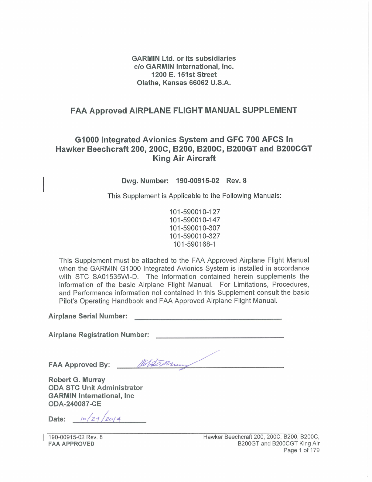
POWER PLANT LIMITATIONS AND INDICATOR MARKINGS
No changes were made to the airplane’s engine operating limits. The engine gauges are marked as
shown in the following tables. Refer to the latest Airplane Flight Manual or appropriate Airplane Flight
Manual Supplement for engine and propeller limitations.
OPERATING
PARAMETER
Torque (ft-lbs) -- -- 0 to 2230 -- 2230 (1)
ITT (ºC) -- -- 400 to 750 -- 750 (2)
Prop N2 (rpm) -- -- (3) -- (3)
Gas Generator N1 (%) -- -- 52 to 101.5 -- 101.5 (4)
Oil Temp. (ºC) -40 (5) -40 to +10 (5) 10 to 99 (5) 99 to 104 (5) 99 (5)
Oil
Press.
(psi)
Less than
21,000’ MSL.
21,000’ MSL
and above
Red Arc/Radial
(Minimum Limit)
PT6A-41 ENGINES COLOR MARKINGS & RANGES
Yellow Arc
(Caution)
60 to 105 105 to 135
60
60 to 85 85 to 135
Green Arc
(Normal)
Yellow Arc
(Caution)
-- 135 (6)(7)
Red Arc/Radial
(Maximum
Limit)
Footnotes:
(1) The maximum transient torque value is 2750 ft-lb for up to 5 seconds. Within this transient
value, the torque indicator will display green digits and a white pointer. After 5 seconds, the digits
will flash alternating red and white background with a flashing red pointer for 5 seconds. After 5
seconds of flashing, the indication is steady white digits/red background and the pointer is red.
Above 2750 FT-LB, the indication immediately begins flashing for 5 seconds before displaying
steady white digits on a red background and a red pointer.
(2) A red diamond at 1000°C represents the upper transient limit for engine Starting Mode. Normally,
the ITT indicator will display green digits and a white pointer. Above 800°C, or when between
750°C and 800°C for more than 5 seconds, (or above 1000°C for more than 5 seconds in Starting
Mode), the digital indication will flash alternating red and white background with a flashing red
pointer for 5 seconds. After 5 seconds of flashing, the indication is steady white digits/red
background and the pointer is red.
(3) See PROPELLER TYPES AND INDICATOR MARKINGS table.
(4) The maximum transient N1 value is 102.6% for up to 10 seconds. Within this transient value, the
N1 indicator will display green digits and a white pointer. When between 101.5% and 102.6% for
more than 10 seconds, or when above 102.6%, the digital indication will flash alternating red and
white background with a flashing red pointer for 5 seconds. After 5 seconds of flashing, the
indication is steady white digits/red background and the pointer is red.
(5) Above 104°C, or between 99°C and 104°C for more than 5 minutes, the digital indication will flash
alternating red and white background with a flashing red pointer for 5 seconds. After 5 seconds
of flashing, the indication is steady white digits/red background and the pointer is red. Below 0°C
to -40°C, the digital indication will be black digits on a yellow background. Below -40°C, the
digital indication will be white digits on a red background.
(6) Above 135 PSI, or below 60 PSI and decreasing oil pressure, the digital indication will flash
alternating red and white background with a flashing red pointer for 5 seconds. After 5 seconds
of flashing, the indication is steady white digits/red background and the pointer is red.
(7) A red diamond at 200 psi represents the upper transient limit.
Hawker Beechcraft 200, 200C, B200, B200C, 190-00915-02 Rev. 8
B200GT and B200CGT King Air FAA APPROVED
Page 20 of 179
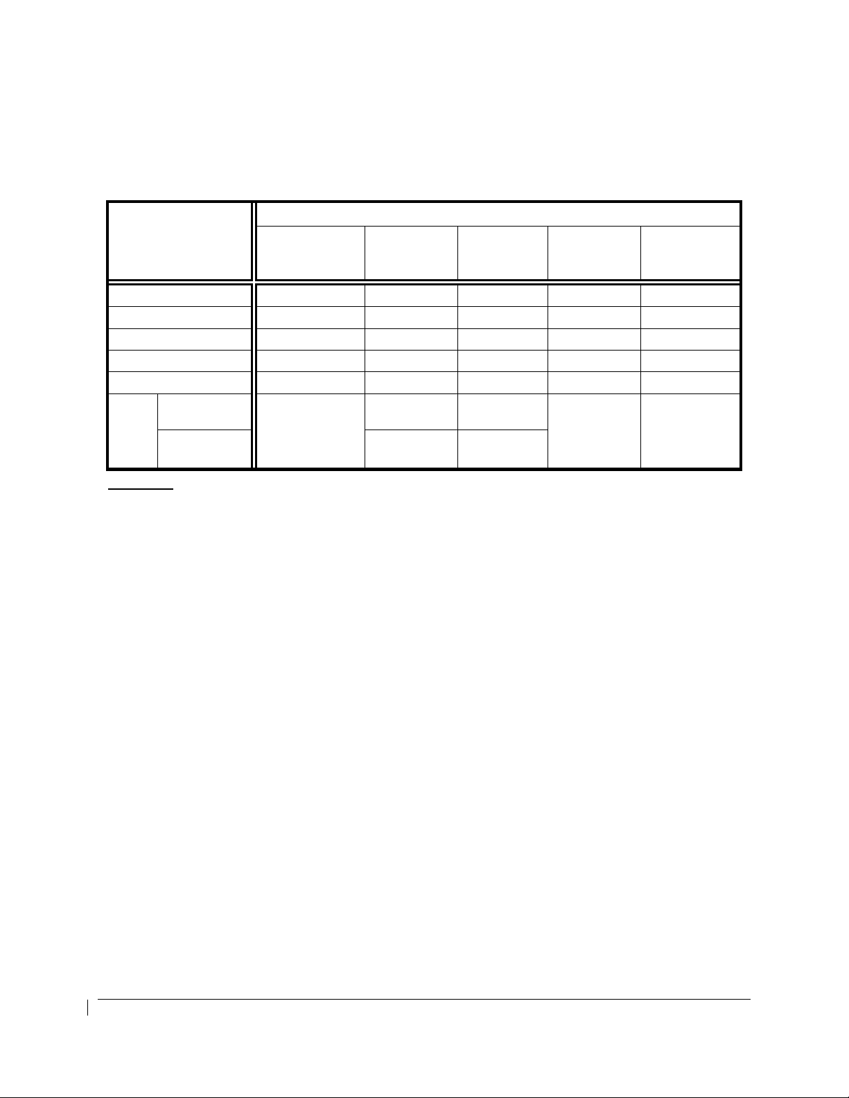
OPERATING
PARAMETER
Torque (ft-lbs) -- -- 0 to 2230 -- 2230 (1)
ITT (ºC) -- -- 400 to 800 -- 800 (2)
Prop N2 (rpm) -- -- (3) -- (3)
Gas Generator N1 (%) -- -- 61 to 101.5 -- 101.5 (4)
Oil Temp. (ºC) -40 (5) -40 to 0 (5) 0 to 99 (5) 99 to 104 99 (5)
Oil
Press.
(psi)
Less than
21,000’ MSL.
21,000’ MSL
and above
Red Arc/Radial
(Minimum Limit)
PT6A-42 ENGINES COLOR MARKINGS & RANGES
Yellow Arc
(Caution)
60 to 100 100 to 135
60
60 to 85 85 to 135
Green Arc
(Normal)
Yellow Arc
(Caution)
-- 135 (6)(7)
Red Arc/Radial
(Maximum Limit)
Footnotes:
(1) The maximum transient torque value is 2750 ft-lb for up to 5 seconds. Within this transient
value, the torque indicator will display green digits and a white pointer. After 5 seconds, the digits
will flash alternating red and white background with a flashing red pointer for 5 seconds. After 5
seconds of flashing, the indication is steady white digits/red background and the pointer is red.
Above 2750 FT-LB, the indication immediately begins flashing for 5 seconds before displaying
steady white digits on a red background and a red pointer.
(2) A red diamond at 1000°C represents the upper transient limit for engine Starting Mode. The
lower Normal Mode transient limit is 850°C. Within this transient value, the ITT indicator will
display green digits and a white pointer. After 20 seconds between 800
°
C and 850°C (or above
1000°C for more than 5 seconds in Starting Mode), the digital indication will flash alternating red
and white background with a flashing red pointer for 5 seconds. After 5 seconds of flashing, the
indication is steady white digits/red background and the pointer is red. In Normal Mode while
above 850
°
C, the indication immediately begins flashing for 5 seconds before displaying steady
white digits on a red background and a red pointer.
(3) See PROPELLER TYPES AND INDICATOR MARKINGS table.
(4) The maximum transient N1 value is 102.6% for up to 10 seconds. Within this transient value, the
N1 indicator will display green digits and a white pointer. When between 101.5% and 102.6% for
more than 10 seconds, or when above 102.6%, the digital indication will flash alternating red and
white background with a flashing red pointer for 5 seconds. After 5 seconds of flashing, the
indication is steady white digits/red background and the pointer is red.
(5) Above 104°C, or between 99°C and 104°C for more than 10 minutes, the digital indication will
flash alternating red and white background with a flashing red pointer for 5 seconds. After 5
seconds of flashing, the indication is steady white digits/red background and the pointer is red.
Below 0°C to -40°C, the digital indication will be black digits on a yellow background. Below
-40°C, the digital indication will be white digits on a red background.
(6) Above 135 PSI, or below 60 PSI and decreasing oil pressure, the digital indication will flash
alternating red and white background with a flashing red pointer for 5 seconds. After 5 seconds
of flashing, the indication is steady white digits/red background and the pointer is red.
(7) A red diamond at 200 psi represents the upper transient limit.
190-00915-02 Rev. 8 Hawker Beechcraft 200, 200C, B200, B200C,
FAA APPROVED B200GT and B200CGT King Air
Page 21 of 179
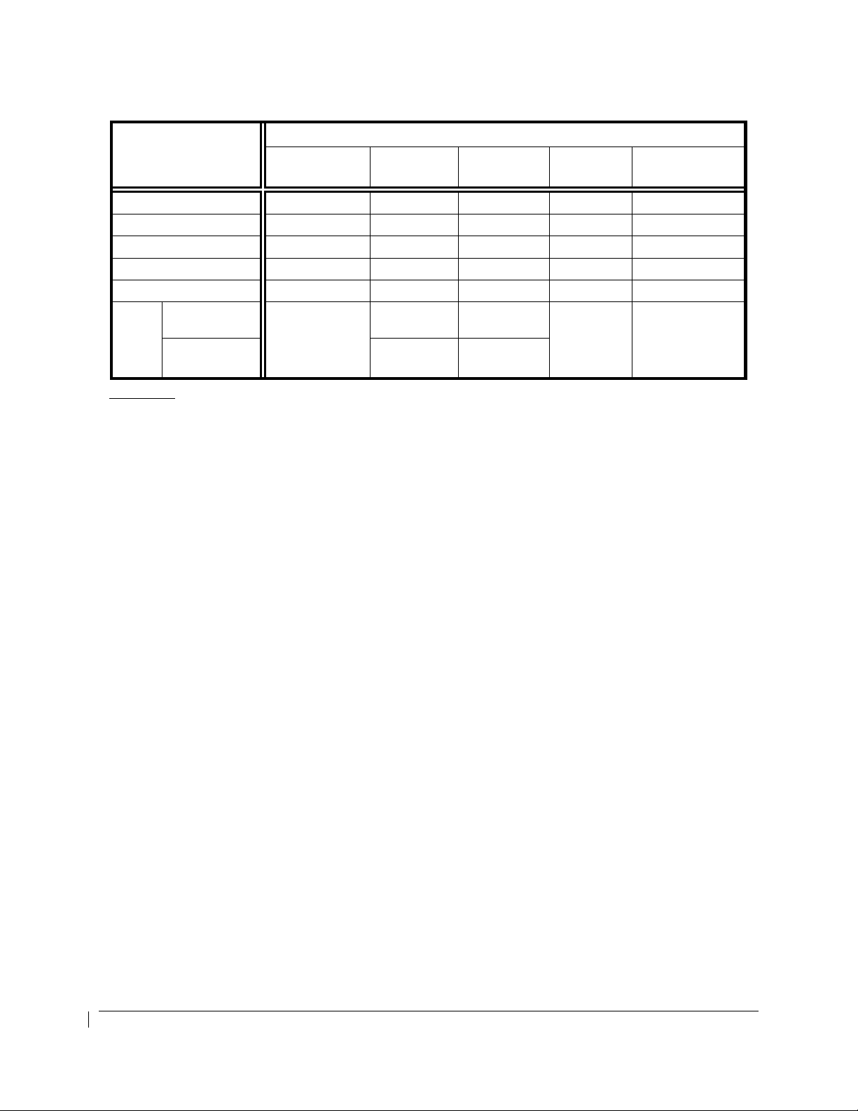
OPERATING
PARAMETER
Torque (ft-lbs) -- -- 0 to 2230 -- 2230 (1)
ITT (ºC) -- -- 400 to 820 -- 820 (2)
Prop N2 (rpm) -- -- (3) -- (3)
Gas Generator N1 (%) -- -- 61 to 104 -- 104 (4)
Oil Temp. (ºC) -40 (5) -40 to 0 (5) 0 to 110 (5) -- 110 (5)
Oil
Press.
(psi)
Less than
21,000’ MSL.
21,000’ MSL and
above
Red Arc/Radial
(Minimum Limit)
PT6A-52 ENGINES COLOR MARKINGS & RANGES
Yellow Arc
(Caution)
60 to 90 90 to 135
60
60 to 85 85 to 135
Green Arc
(Normal)
Yellow Arc
(Caution)
-- 135 (6)(7)
Red Arc/Radial
(Maximum Limit)
Footnotes:
(1) The maximum transient torque value is 2750 ft-lb for up to 5 seconds. Within this transient
value, the torque indicator will display green digits and a white pointer. After 5 seconds, the digits
will flash alternating red and white background with a flashing red pointer for 5 seconds. After 5
seconds of flashing, the indication is steady white digits/red background and the pointer is red.
Above 2750 FT-LB, the indication immediately begins flashing for 5 seconds before displaying
steady white digits on a red background and a red pointer.
(2) A red diamond at 1000°C represents the upper transient limit for engine Starting Mode. The
lower Normal Mode transient limit is 850°C. Within this transient value, the ITT indicator will
display green digits and a white pointer. After 20 seconds between 820
°
C and 850°C (or above
1000°C for more than 5 seconds in Starting Mode), the ITT digital indication will flash alternating
red and white background with a flashing red pointer for 5 seconds. After 5 seconds of flashing,
the indication is steady white digits/red background and the pointer is red. In Normal Mode while
above 850
°
C, the indication immediately begins flashing for 5 seconds before displaying steady
white digits on a red background and a red pointer.
(3) See PROPELLER TYPES AND INDICATOR MARKINGS table.
(4) Above 104%, the digital indication will flash alternating red and white background with a flashing
red pointer for 5 seconds. After 5 seconds of flashing, the indication is steady white digits/red
background and the pointer is red
(5) Above 110°C, the digital indication will flash alternating red and white background with a
flashing red pointer for 5 seconds. After 5 seconds of flashing, the indication is steady white
digits/red background and the pointer is red. Below 0°C to -40°C, the digital indication will be
black digits on a yellow background. Below -40°C, the digital indication will be white digits on a
red background.
(6) Above 135 PSI, or below 60 PSI and decreasing oil pressure, the digital indication will flash
alternating red and white background with a flashing red pointer for 5 seconds. After 5 seconds
of flashing, the indication is steady white digits/red background and the pointer is red.
(7) A red diamond at 200 psi represents the upper transient limit.
Hawker Beechcraft 200, 200C, B200, B200C, 190-00915-02 Rev. 8
B200GT and B200CGT King Air FAA APPROVED
Page 22 of 179

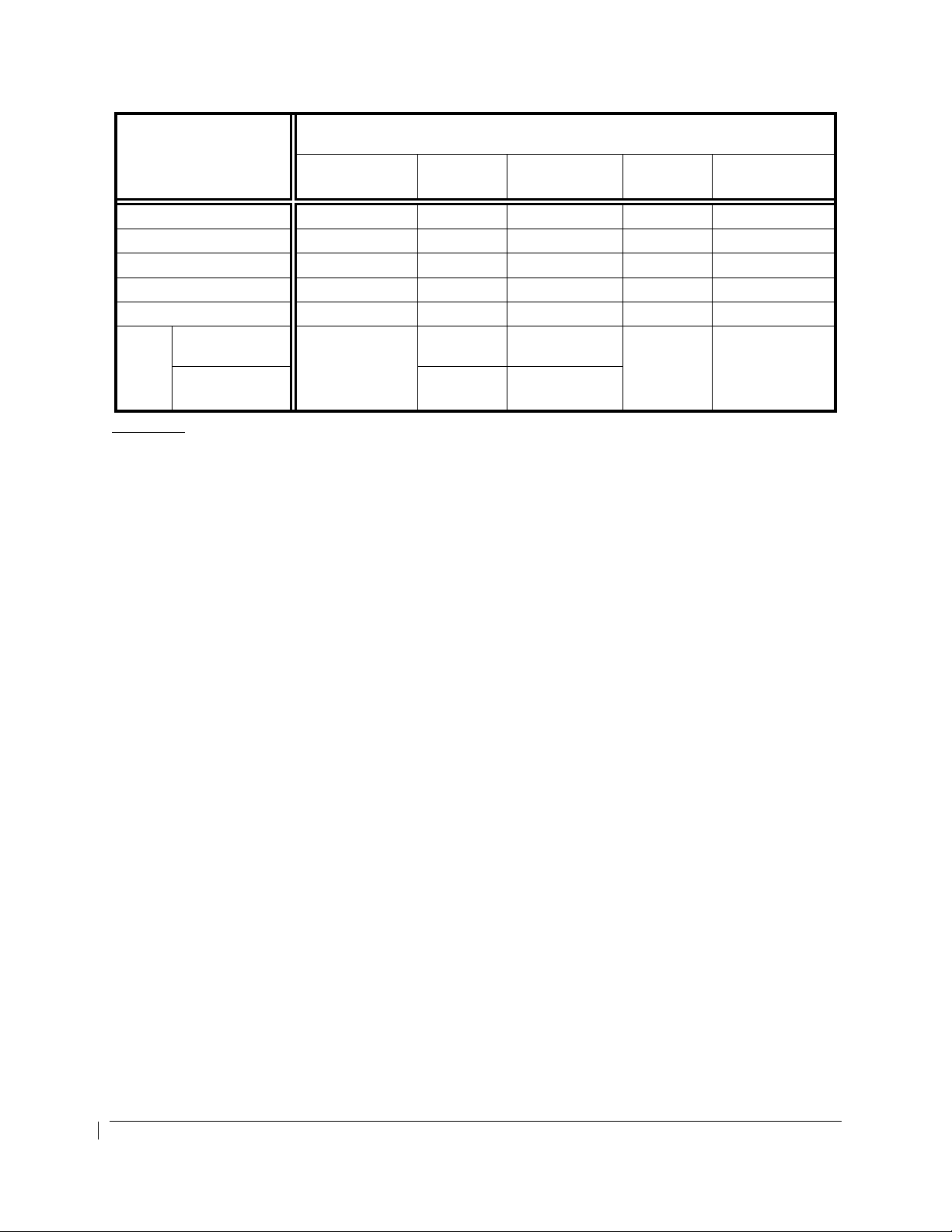
OPERATING
PARAMETER
Torque (ft-lbs) -- -- 0 to 2230 -- 2230 (1)
ITT (ºC) -- -- 400 to 800 -- 800 (2)
Prop N2 (rpm) -- -- (3) -- (3)
Gas Generator N1 (%) -- -- 61 to 104 -- 104 (4)
Oil Temp. (ºC) -40 (5) -40 to 0 (5) 0 to 110 (5) -- 110 (5)
Oil
Press.
(psi)
Less than
21,000’ MSL.
21,000’ MSL and
above
Red Arc/Radial
(Minimum Limit)
PT6A-61 ENGINES COLOR MARKINGS & RANGES
Yellow Arc
(Caution)
60 to 90 90 to 135
60
60 to 85 85 to 135
Green Arc
(Normal)
Yellow Arc
(Caution)
-- 135 (6)(7)
Red Arc/Radial
(Maximum Limit)
Footnotes:
(1) The maximum transient torque value is 2750 ft-lb for up to 5 seconds. Within this transient
value, the torque indicator will display green digits and a white pointer. After 5 seconds, the digits
will flash alternating red and white background with a flashing red pointer for 5 seconds. After 5
seconds of flashing, the indication is steady white digits/red background and the pointer is red.
Above 2750 FT-LB, the indication immediately begins flashing for 5 seconds before displaying
steady white digits on a red background and a red pointer.
(2) A red diamond at 1000°C represents the upper transient limit for engine Starting Mode. The
lower Normal Mode transient limit is 850°C. Within this transient value, the ITT indicator will
display green digits and a white pointer. After 20 seconds between 800
°
C and 850°C (or above
1000°C for more than 5 seconds in Starting Mode), the ITT digital indication will flash alternating
red and white background with a flashing red pointer for 5 seconds. After 5 seconds of flashing,
the indication is steady white digits/red background and the pointer is red. In Normal Mode while
above 850
°
C, the indication immediately begins flashing for 5 seconds before displaying steady
white digits on a red background and a red pointer.
(3) See PROPELLER TYPES AND INDICATOR MARKINGS table.
(4) Above 104%, the digital N1 indication will flash alternating red and white background with a
flashing red pointer for 5 seconds. After 5 seconds of flashing, the indication is steady white
digits/red background and the pointer is red
(5) Above 110°C, the digital N1 indication will flash alternating red and white background with a
flashing red pointer for 5 seconds. After 5 seconds of flashing, the indication is steady white
digits/red background and the pointer is red. Below 0°C to -40°C, the digital indication will be
black digits on a yellow background. Below -40°C, the digital indication will be white digits on a
red background.
(6) Above 135 PSI, or below 60 PSI and decreasing oil pressure, the digital indication will flash
alternating red and white background with a flashing red pointer for 5 seconds. After 5 seconds
of flashing, the indication is steady white digits/red background and the pointer is red.
(7) A red diamond at 200 psi represents the upper transient limit.
190-00915-02 Rev. 8 Hawker Beechcraft 200, 200C, B200, B200C,
FAA APPROVED B200GT and B200CGT King Air
Page 23 of 179

PROPELLER TYPES AND INDICATOR MARKINGS
Manufacturer Hartzell Hartzell Hartzell Hartzell McCauley McCauley
Hub
Blades T10178()-3R
Normal
Operating
Range – RPM
(Green Arc)
Maximum Limit
– RPM (Red
Radial)
Transient Limit
- RPM
HC-B3TN-3G
or -3N
1600-2000 1150-2000 1180-2000 1180-2000 1600-2000 1100-2000
2000 2000 2000 2000 2000 2000
2200 (1) 2200 (2) 2200 (2) 2200 (1) 2200 (1) 2200 (1)
HC-D4N-3A HC-E4N-3G HC–E4N-3A 3GFR34C702
D9383K
Or
D9515K
D9390SK-1R NC9208K 100LA-2 94LA-0
4HFR34C771
4HFR34C754
Footnotes:
(1) This value is time limited to 5 seconds. Within the transient value, the torque indicator will display
green digits and a white pointer. After 5 seconds, the digits will flash alternating red and white
background with a flashing red pointer for 5 seconds. After 5 seconds of flashing, the indication
is steady white digits/red background and the pointer is red. Above 2200 RPM, the indication
immediately begins flashing for 5 seconds before displaying steady white digits on a red
background and a red pointer.
(2) This value is time limited to 20 seconds. Within the transient value, the torque indicator will
display green digits and a white pointer. After 20 seconds, the digits will flash alternating red and
white background with a flashing red pointer for 5 seconds. After 5 seconds of flashing, the
indication is steady white digits/red background and the pointer is red. Above 2200 RPM, the
indication immediately begins flashing for 5 seconds before displaying steady white digits on a red
background and a red pointer.
Hawker Beechcraft 200, 200C, B200, B200C, 190-00915-02 Rev. 8
B200GT and B200CGT King Air FAA APPROVED
Page 24 of 179

MANEUVER LIMITS
No changes have been made to the airplane’s maneuver limits. The Hawker Beechcraft Super King Air
200, 200C, B200 and B200C are Normal Category airplanes. Acrobatic maneuvers, including spins, are
prohibited.
RVSM OPERATIONS
RVSM operations are prohibited if the static ports are damaged or surface irregularities are found within
the RVSM critical region.
The pilot and copilot PFDs must display on-side ADC information during RVSM operations.
G1000 INTEGRATED AVIONICS SYSTEM
Tuning of the COM and NAV radios using the GCU477 controller must be done from the Left seat pilot’s
station and only referencing the pilot’s PFD.
Required flight crewmembers must wear and use headsets when the overhead cockpit speaker audio is
selected OFF.
Do not take off unless all display units are installed and operational.
Do not take off with any display in reversionary mode.
Do not take off with any of the following messages displayed in the ALERTS window:
GPS1 FAIL and GPS2 FAIL simultaneously PFD1 SERVICE
GPS NAV LOST PFD2 SERVICE
GIA1 SERVICE GMA1 SERVICE
GIA2 SERVICE GMA2 SERVICE
MFD SERVICE GEO LIMITS
The G1000 system must be turned on and operated for at least 30 minutes before takeoff if ground outside
air temperature is -40°C (-40°F) or below.
The following temperature limitations apply only to aircraft with G1000 systems installed per Garmin
drawing 005-00421-00 Revision 15 or previous and not
• Do not takeoff if the PFD1 FAN FAIL, PFD2 FAN FAIL or MFD FAN FAIL is displayed in the ALERTS
window AND the Outside Air Temperature is greater than 41°C (106°F) AND cabin air conditioning is
inoperative.
• Do not takeoff if GIA1 FAN FAIL or GIA2 FAN FAIL is displayed in the ALERTS window AND the
Outside Air Temperature is greater than 42°C (107°F).
• Ground operation of the G1000 system is limited to 18 minutes when the Outside Air Temperature is
greater than 47°C (116°F) AND cabin air conditioning is inoperative.
modified by Garmin service bulletin No. 1375:
.
190-00915-02 Rev. 8 Hawker Beechcraft 200, 200C, B200, B200C,
FAA APPROVED B200GT and B200CGT King Air
Page 25 of 179

For airplanes with system software 0985.06 or earlier, use of VNAV is prohibited during the intermediate
segment of an approach that includes a teardrop course reversal. VNAV will become ‘Unavailable’ at the
beginning of the teardrop segment of the course reversal.
Use of VNAV is prohibited with course changes greater than 90°.
The barometric altimeter must be used as the primary altitude reference for all baro VNAV operations,
including instrument approach procedure step-down fixes. Use of baro VNAV to a DA is not authorized
with a remote altimeter setting. A current altimeter setting for the landing airport is required. When
using remote altimeter minima, the baro VNAV function may be used to the published LNAV MDA.
When a flight is predicated on flying a RNP approach with an RF leg at the destination and/or alternate, the
pilot must determine that the AFCS is operational. At a minimum, the flight director must be displayed
and utilized when conducting procedures containing Radius-to-Fix (RF) segments.
For airplanes with 0985.07 system software, Vector-to-Final transitions are prohibited for the following
approaches:
• CYSB VOR/DME Rwy 12
• NZTH GPS 330
• TTPP ILS Rwy 10
The fuel quantity, fuel required, fuel remaining, and gross weight estimate functions of the G1000 are
supplemental information only and must be verified by the flight crew.
Do not use SafeTaxi or Chartview functions as the basis for ground maneuvering. SafeTaxi and
Chartview functions do not comply with the requirements of AC 20-159 and are not qualified to be used as
an airport moving map display (AMMD). SafeTaxi and Chartview are to be used by the flight crew to
orient themselves on the airport surface to improve pilot situational awareness during ground operations.
The use of the colors red and amber within the checklist function has not been evaluated or approved by
this STC. Use of the colors red and/or amber within user created checklists may require separate
evaluation and approval by the FAA.
Hawker Beechcraft 200, 200C, B200, B200C, 190-00915-02 Rev. 8
B200GT and B200CGT King Air FAA APPROVED
Page 26 of 179

G1000 GNSS (GPS/SBAS) NAVIGATION SYSTEM LIMITATIONS
NOTE
Limitations are in bolded text for this section only.
The flight crew must confirm at system initialization that the Navigation database is current.
The Navigation database is expected to be current for the duration of the flight. If the AIRAC c ycle will
change during flight, the flight crew must ensure the accuracy of navigation data, including
suitability of navigation facilities used to define the routes and procedures for flight. If an
amended chart affecting navigation data is published for the procedure, the database must not be
used to conduct the procedure.
GPS/SBAS based IFR enroute, oceanic, and terminal navigation is prohibited unless the flight crew
verifies and uses a valid, compatible, and current Navigation database or verifies each waypoint
for accuracy by reference to current approved data.
Discrepancies that invalidate a procedure must be reported to Garmin International. The affected
procedure is prohibited from being flown using data from the Navigation database until a new
Navigation database is installed in the aircraft and verified that the discrepancy has been
corrected. Navigation database discrepancies can be reported at FlyGarmin.com then select “Aviation
Data Error Report”. Flight crew and operators can view Navigation data base alerts at FlyGarmin.com
then select “NavData Alerts”.
For flight planning purposes, in areas where SBAS coverage is not available, the flight crew must
check RAIM availability. Within the United States, RAIM availability can be determined via the
following:
• Using G1000 WFDE Prediction program, part number 006-A0154-01 (010-G1000-00) or later
approved version with GARMIN GA36 and GA37 antennas selected.
• Via the FAA’s en route and terminal RAIM prediction website: www.raimprediction.net.
• Contacting a Flight Service Station (not DUATS) to obtain non-precision approach RAIM.
Within Europe, RAIM availability can be determined using the G1000 WFDE Prediction program or
Europe’s AUGER GPS RAIM Prediction Tool at http://augur.ecacnav.com/augur/app/home. For other
areas, use the G1000 WFDE Prediction program. This requirement is not necessary if SBAS coverage is
confirmed to be available along the entire route of flight. The route planning and WFDE prediction
program may be downloaded from the GARMIN G1000 website on the internet. For information on using
the WFDE Prediction Program, refer to GARMIN WAAS FDE Prediction Program, part number
190-00643-01, ‘WFDE Prediction Program Instructions’.
For flight planning purposes, operations within the U.S. National Airspace System on RNP and
RNAV procedures when SBAS signals are not available, the availability of GPS integrity RAIM shall
be confirmed for the intended route of flight. In the event of a predicted continuous loss of RAIM of
more than five minutes for any part of the intended route of flight, the flight should be delayed, canceled, or
re-routed on a track where RAIM requirements can be met.
For flight planning purposes for operations within European B-RNAV and P-RNAV airspace, if
more than one satellite is scheduled to be out of service, then the availability of GPS integrity RAIM
shall be confirmed for the intended flight (route and time). In the event of a predicted continuous loss
of RAIM of more than five minutes for any part of the intended flight, the flight should be delayed, canceled,
or re-routed on a track where RAIM requirements can be met.
190-00915-02 Rev. 8 Hawker Beechcraft 200, 200C, B200, B200C,
FAA APPROVED B200GT and B200CGT King Air
Page 27 of 179

For flight planning purposes, operations where the route requires Class II navigation the aircraft’s
operator or flight crew must use the Garmin WFDE Prediction program to demonstrate that there
are no outages on the specified route that would prevent the G1000 from providing primary means
of Class II navigation in oceanic and remote areas of operation that requires (RNP-10 or RNP-4)
capability. If the Garmin WFDE Prediction program indicates fault exclusion (FDE) is unavailable for
more than 34 minutes in accordance with FAA Order 8400.12C for RNP-10 requirements, or 25 minutes in
accordance with FAA Order 8400.33 for RNP-4 requirements, then the operation must be rescheduled
when FDE is available.
Both GIA 63W GPS/SBAS receivers must be operating and providing GPS navigation guidance to
their respective PFD for operations requiring RNP-4 performance.
North Atlantic (NAT) Minimum Navigational Performance Specifications (MNPS) Airspace operations per
AC 91-49 and AC 120-33 require both GIA 63W GPS/SBAS receivers to be operating and receiving
usable signals except for routes requiring only one Long Range Navigation sensor. Each display computes
an independent navigation solution based on the on-side GPS sensor. However, either display will
automatically revert to the cross-side sensor if the on-side sensor fails or if the cross-side sensor is
determined to be more accurate. A “BOTH ON GPS1” or “BOTH ON GPS2” message does not necessarily
mean that one GPS has failed. Refer to the MFD AUX-GPS STATUS page to determine the state of the
unused GPS.
Manual entry of waypoints using latitude/longitude or place/bearing is prohibited. Whenever
possible, RNP and RNAV routes including Standard Instrument Departures (SIDs) and Obstacle
Departure Procedures (ODPs), Standard Terminal Arrival (STAR), and en route RNAV “Q” and RNAV “T”
routes should be loaded into the flight plan from the database in their entirety, rather than loading route
waypoints from the database into the flight plan individually. Selecting and inserting individual named
fixes from the database is permitted, provided all fixes along the published route to be flown are inserted.
“GPS”, “or GPS”, “RNAV(GPS)”, or “RNAV(GNSS)” instrument approaches using the G1000
System are prohibited unless the flight crew verifies and uses the current Navigation database.
GPS based instrument approaches must be flown in accordance with an approved instrument
approach procedure that is loaded from the Navigation database.
Not all published Instrument Approach Procedures (IAP) are in the Navigation database. Flight crew
planning on flying an RNAV instrument approach must ensure that the Navigation database
contains the planned RNAV Instrument Approach Procedure and that approach procedure must b e
loaded from the Navigation database into the FMS flight plan by its name.
IFR non-precision approach approval using the GPS/SBAS sensor is limited to published
approaches within the U.S. National Airspace System. Approaches to airports in other airspace are
not approved unless authorized by the appropriate governing authority.
When operating under instrument flight rules, flight plan selection of any required alternate airport may be
based on an RNAV approach. For airplanes with system software 0985.06 or earlier, alternate airport
selection must be based upon an LNAV approach or an available ground-based approach for which the
aircraft is equipped to fly.
For airplanes that have system software 0985.07 or later installed, alternate airport selection may based
upon LNAV, LNAV/VNAV (when baro-VNAV is used), or other available ground-based approaches for
which the aircraft is equipped to fly. Alternate planning may include the use of an LNAV MDA(h) for
circling or LNAV/VNAV DA(h) when baro-VNAV is active.
The navigation equipment required to join and fly an instrument approach procedure is indicated by the
title of the procedure and notes on the IAP chart. Use of the GARMIN G1000 GPS/SBAS receivers to
provide navigation guidance during the final approach segment of an ILS, LOC, LOC-BC, LDA,
Hawker Beechcraft 200, 200C, B200, B200C, 190-00915-02 Rev. 8
B200GT and B200CGT King Air FAA APPROVED
Page 28 of 179

SDF, MLS or any other type of approach not approved for “or GPS” navigation is prohibited.
When using the G1000 VOR/LOC/GS receivers to fly the final approach segment, VOR/LOC/GS
navigation data must be selected and presented on the CDI of the pilot flying.
For airplanes that have system software 0985.07 or later installed, all VNAV altitude constraints must be
manually entered by the flight crew. The system will not auto-nominate VNAV altitude constraints.
Navigation information is referenced to WGS-84 reference system, and should only be used where the
Aeronautical Information Publication (including electronic data and aeronautical charts) conform to
WGS-84 or equivalent.
190-00915-02 Rev. 8 Hawker Beechcraft 200, 200C, B200, B200C,
FAA APPROVED B200GT and B200CGT King Air
Page 29 of 179

AHRS AREAS OF OPERATION
For airplanes that have GRS 77 AHRS installed:
Flight operations with the G1000 Integrated Avionics installed are prohibited in the following regions due to
unsuitability of the magnetic fields near the Earth’s poles:
1. North of 72° North latitude at all longitudes
2. South of 70° South latitude at all longitudes
3. North of 65° North latitude between longitude 75° W and 120° W (Northern Canada)
4. North of 70° North latitude between longitude 70° W and 128° W (Northern Canada)
5. North of 70° North latitude between longitude 85° E and 114° E (Northern Russia)
6. South of 55° South latitude between longitude 120° E and 165° E (Region south of Australia and
New Zealand)
NOTE
The Garmin G1000 system is not designed for use as a polar navigator and operation outside the
approved operating area is prohibited. The GRS-77 AHRS internally monitors the magnetic field
and will display a GEO LIMITS system message when the magnetic field becomes unsuitable for
AHRS operation. When the AHRS can no longer reliably compute heading, heading information
will be removed from the HSI.
For airplanes that have GRS 7800 AHRS installed:
Flight operations in the following regions require heading to be in DG FREE Mode when using system
software version 0985.07:
1. North of 72° North latitude at all longitudes
2. North of 65° North latitude between longitude 75° W and 120° W (Northern Canada)
3. North of 70° North latitude between longitude 70° W and 128° W (Northern Canada)
4. North of 70° North latitude between longitude 85° E and 114° E (Northern Russia)
Flight operations with the G1000 Integrated Avionics installed are prohibited in the following regions due to
unsuitability of the magnetic fields near the Earth’s poles:
1. North of 84° North latitude at all longitudes
2. South of 70° South latitude at all longitudes
3. South of 55° South latitude between longitude 120° E and 165° E (Region south of Australia and
New Zealand)
NOTE
The Garmin G1000 system is not designed for use as a polar navigator and operation outside the
approved operating area is prohibited.
Hawker Beechcraft 200, 200C, B200, B200C, 190-00915-02 Rev. 8
B200GT and B200CGT King Air FAA APPROVED
Page 30 of 179
 Loading...