

Page 1
RV FIXED DISPLAY
INSTALLATION
NOTE: In order for the software update instructions to
appear, the device must be fully booted before the card is
inserted.
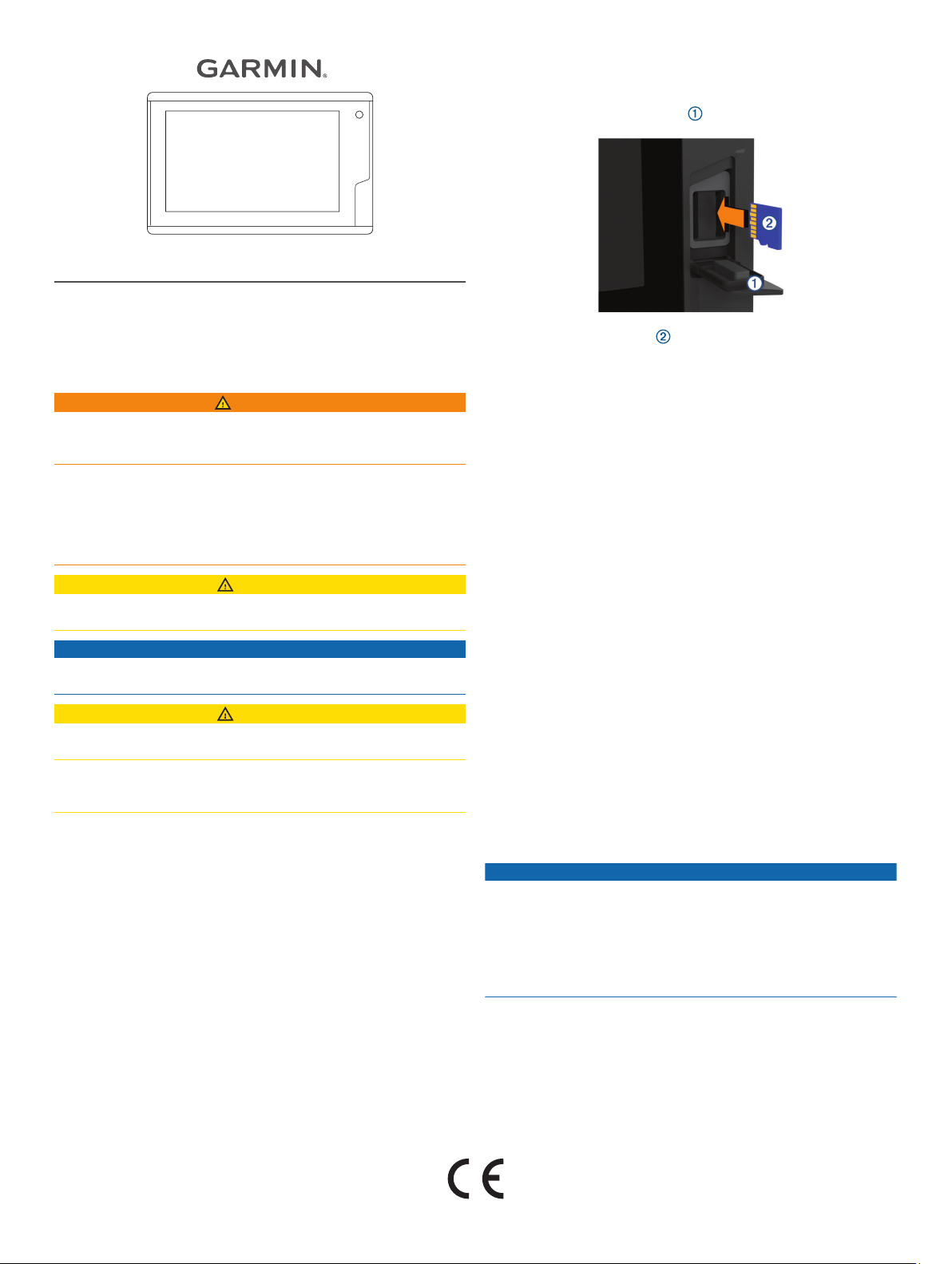
Open the memory card door .
2
INSTRUCTIONS
Important Safety Information
WARNING
See the Important Safety and Product Information guide in the
product box for product warnings and other important
information.
When connecting the power cable, do not remove the in-line
fuse holder. To prevent the possibility of injury or product
damage caused by fire or overheating, the appropriate fuse
must be in place as indicated in the product specifications. In
addition, connecting the power cable without the appropriate
fuse in place voids the product warranty.
CAUTION
Always wear safety goggles, ear protection, and a dust mask
when drilling, cutting, or sanding.
NOTICE
When drilling or cutting, always check what is on the opposite
side of the surface.
CAUTION
To obtain the best performance and to avoid damage to your
RV, install the device according to these instructions.
Read all installation instructions before proceeding with the
installation. If you experience difficulty during the installation,
contact Garmin® Product Support.
Loading the New Software on a Memory Card
Insert a memory card into the card slot on the computer.
1
Go to www.garmin.com, and locate the product page.
2
Select Software from the product page.
3
Select Download.
4
Read and agree to the terms.
5
Select Download.
6
Select Run.
7
Select the drive associated with the memory card, and select
8
Next > Finish.
Updating the Device Software
Before you can update the software, you must obtain a
software-update memory card or load the latest software onto a
memory card.
Turn on the device, and wait for the home screen to appear.
1
Insert the memory card , and press it in until it clicks.
3
Close the door.
4
Follow the on-screen instructions.
5
Wait several minutes while the software update process
6
completes.
The device returns to normal operation after the software
update process is complete.
Remove the memory card.
7
NOTE: If the memory card is removed before the device
restarts fully, the software update is not complete.
Contacting Garmin Support
• Go to support.garmin.com for help and information, such as
product manuals, frequently asked questions, videos, and
customer support.
• In the USA, call 913-397-8200 or 1-800-800-1020.
• In the UK, call 0808 238 0000.
• In Europe, call +44 (0) 870 850 1241.
Tools Needed
• Drill
• 6 mm (1/4 in.) drill bit
• 4 mm (3/16 in.) drill bit
• #2 Phillips screwdriver
• Jigsaw or rotary tool
• File and sandpaper
Mounting Considerations
NOTICE
This device should be mounted in a location that is not exposed
to extreme temperatures or conditions. The temperature range
for this device is listed in the product specifications. Extended
exposure to temperatures exceeding the specified temperature
range, in storage or operating conditions, may cause device
failure. Extreme-temperature-induced damage and related
consequences are not covered by the warranty.
When selecting a mounting location, you should observe these
considerations.
• The location should allow for easy access to all device
interfaces, such as the keypad, touchscreen, and card
reader, if applicable.
• The location must be strong enough to support the weight of
the device and protect it from excessive vibration or shock.
GUID-D7562D38-5D0D-465B-8FF1-97809D4F9CA6 v1March 2020
Page 2
• The location must allow room for the routing and connection
of all cables.
• The location must not be a flat, horizontal surface. The
location should be in a vertical angle.
The location and viewing angle should be tested before you
install the device. High viewing angles from above and below
the display may result in a poor image.
Flush Mounting the Device
NOTICE
Be careful when cutting the hole to flush mount the device.
There is only a small amount of clearance between the case and
the mounting holes, and cutting the hole too large could
compromise the stability of the device after it is mounted.
You can drill holes and use the included template, nut plates,
and machine screws to flush mount the device. The nut plates
can add stability to a thinner surface, and are strongly
recommended for most RV installations.
Trim the template, and make sure it fits in the location where
1
you want to mount the device.
Secure the template to the mounting location.
2
Using a 13 mm (1/2 in.) drill bit, drill one or more of the holes
3
inside the corners of the solid line on the template to prepare
the mounting surface for cutting.
Using a jigsaw or a rotary tool, cut the mounting surface
4
along the inside line on the template.
Place the device in the cutout to test the fit.
5
If necessary, use a file and sandpaper to refine the size of
6
the cutout.
If necessary, remove the trim caps.
7
NOTICE
Use a plastic pry tool when possible. Using a metal pry tool,
such as a screwdriver, can damage the trim caps and the
device.
After the device fits correctly in the cutout, ensure the
8
mounting holes on the device line up with the larger holes on
the template.
If the mounting holes on the device do not line up, mark the
9
new hole locations.
Drill 6 mm (1/4 in.) holes in the larger hole locations.
10
Starting in one corner of the template, place a nut plate
11
over the larger hole drilled in the previous step.
Secure the nut plates to the mounting surface by fastening
17
the smaller machine screws through the smaller holes.
Install the foam gasket on the back of the device.
18
The pieces of the foam gasket have adhesive on the back.
Make sure you remove the protective liner before installing
them on the device.
If you will not have access to the back of the device after you
19
mount it, connect all necessary cables to the device before
placing it into the cutout.
Place the device into the cutout.
20
Secure the device to the mounting surface using the larger
21
machine screws .
Install the trim caps by snapping them in place around the
22
edges of the device.
Connection Considerations
After connecting the cables to the device, tighten the locking
rings to secure each cable.
Power/Wiring Harness Cable
• The wiring harness connects the device to power.
• If it is necessary to extend the wiring harness, you must use
22 AWG (.33 mm²) wire.
The smaller hole on the nut plate should line up with the
smaller hole on the template.
If the smaller hole on the nut plate does not line up with the
12
smaller hole on the template, mark the new hole location.
Drill a 4 mm (3/16 in.) hole in the smaller hole location.
13
Repeat to verify placement of the remaining nut plates and
14
holes on the template.
Remove the template from the mounting surface.
15
Starting in one corner of the mounting location, place a nut
16
plate on the back of the mounting surface, lining up the
large and small holes.
The raised portion of the nut plate should fit into the larger
hole.
2
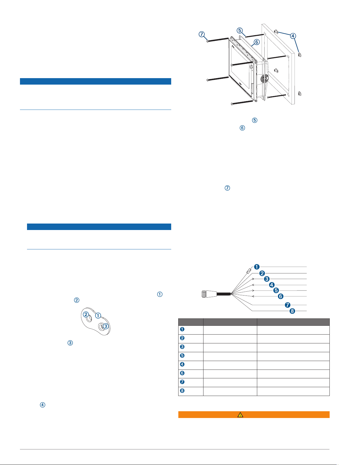
Item Wire Color Wire Function
Red Power
Black Ground (power)
Blue Not used
Gray Not used
Brown Not used
Violet Not used
Orange Accessory on
Yellow Not used
Connecting the Wiring Harness to Power
WARNING
When connecting the power cable, do not remove the in-line
fuse holder. To prevent the possibility of injury or product
damage caused by fire or overheating, the appropriate fuse
must be in place as indicated in the product specifications. In
Page 3

addition, connecting the power cable without the appropriate
fuse in place voids the product warranty.
Route the wiring harness to the power source and to the
1
device.
Connect the red wire to the positive (+) battery terminal, and
2
connect the black wire to the negative (-) battery terminal.
If necessary, install the locking ring and O-ring on the end of
3
the wiring harness.
Insert the cable into the POWER connector on the back of
4
the device, pushing firmly.
Turn the locking ring clockwise to attach the cable to the
5
device.
Additional Grounding Consideration
This consideration is applicable only to devices that have a
grounding screw. Not all models have a grounding screw.
This device should not need additional chassis grounding in
most installation situations.
NMEA 2000® Considerations
NOTICE
If you are connecting to an existing NMEA 2000 network,
identify the NMEA 2000 power cable. Only one NMEA 2000
power cable is required for the NMEA 2000 network to operate
properly.
A NMEA 2000 Power Isolator (010-11580-00) should be used in
installations where the existing NMEA 2000 network
manufacturer is unknown.
If you are installing a NMEA 2000 power cable, you must
connect it to the RV ignition switch or through another in-line
switch. NMEA 2000 devices will drain your battery if the NMEA
2000 power cable is connected to the battery directly.
This device can connect to a NMEA 2000 network on your RV to
share data from NMEA 2000 compatible devices such as a VHF
radio. The included NMEA 2000 cables and connectors allow
you to connect the device to your existing NMEA 2000 network.
If you do not have an existing NMEA 2000 network you can
create a basic one using cables from Garmin.
To use a FUSION® stereo and digital switching server, you must
connect the devices to the same NMEA 2000 network.
If you are unfamiliar with NMEA 2000, you should read the
“NMEA 2000 Network Fundamentals” chapter of the Technical
Reference for NMEA 2000 Products. You can find this document
using the “Manuals” link on the product page for your device at
www.garmin.com.
The port labeled NMEA 2000 is used to connect the device to a
standard NMEA 2000 network.
FUSION stereo
RV Fixed Display
Digital switching server
In-line switch
NMEA 2000 power cable
NMEA 2000 cable from the stereo
This can be extended to a maximum length of 6 m (20 ft.) using a
NMEA 2000 cable.
NMEA 2000 drop cable
NMEA 2000 drop cable
NMEA 2000 terminator or backbone cable
NMEA 2000 T-connector
Composite Video Considerations
This device allows video input from composite video sources
using the port labeled CVBS IN. When connecting composite
video, you should observe these considerations.
• The CVBS IN port uses a BNC connector. You can use a
BNC to RCA adapter to connect a composite-video source
with RCA connectors to the CVBS IN port.
• Video is not shared across the NMEA 2000 network.
Accessing the RV Builder Settings
Select Settings > My RV.
1
Hold the upper-left corner of the screen
2
The RV Builder Settings option appears in the menu.
Select RV Builder Settings.
3
The RV Builder Settings are accessible until you turn the device
off and on, or hold the upper-left corner of the screen again.
Customizing the Startup Screen
You can set your company logo or another image to be
displayed while the device is turning on. For the best fit, the
image should be 50 MB or less, should not have transparency,
and should conform to the recommended dimensions
(Recommended Startup Image Dimensions, page 4).
Insert a memory card that contains the image you want to
1
use.
From the RV Builder Settings, select Startup Image >
2
Select Image.
Select the memory card slot.
3
Select the image.
4
Select Set as Startup Image.
5
To view the startup screen with the new image, turn the device
off and on.
3
Page 4

Recommended Startup Image Dimensions
For the best fit for the startup images, use an image that has the
following dimensions, in pixels.
Display resolution Image width Image height
WVGA 680 200
WSVGA 880 270
WXGA 1080 350
HD 1240 450
WUXGA 1700 650
Home Page Customization
Customizing the Home Page
From the RV Builder Settings, select Customize Home
1
Page > Edit Home Page > Add Item.
Select an item:
2
• To add a button to open a page, select Page Button.
• To add a switch, select Switch.
• To add a gauge, select Gauge.
• To add an overlay bar, select Overlay Bar.
Select an option to edit an item:
3
• To move an item, drag it to the new location.
• To layer the item in front of another item, select Move to
Front.
• To layer the item behind another item, select Move to
Back.
• To change the page the button opens, select Replace
Layout, and select the page to open.
• To change the item a switch controls, select Replace
Switch, and select the item.
• To change the data shown in a gauge, select Replace
Data, and select the data.
• To change the data shown in an overlay bar, select
Replace Overlay Bar, and select the bar.
• To remove the item, select Remove.
Select Home to view your custom home page.
4
Customizing the Home Page Background
You can customize the background image. For the best fit, the
image should be 50 MB or less, should not have transparency,
and should conform to the recommended dimensions
(Recommended Background Image Dimensions, page 4).
Insert a memory card that contains the image you want to
1
use.
From the RV Builder Settings, select Customize Home
2
Page > Edit Home Page > Background > Select Image.
Select the memory card slot.
3
Select the image.
4
Recommended Background Image Dimensions
For the best fit for the background image, use an image that has
the following dimensions, in pixels.
Display resolution Image width Image height
WVGA 800 430
WSVGA 1024 535
WXGA 1380 723
HD 1920 991
WUXGA 1920 1111
Adding and Editing a Digital Switching Page
You can add and customize digital switching pages for some
compatible digital switching systems.
Select Switching > Menu.
1
Set up the page as needed:
2
• To enter a name for the page, select Name.
• To set up the switches, select Edit Switches.
Troubleshooting
My device will not turn on or keeps turning off
Devices erratically turning off or not turning on could indicate an
issue with the power supplied to the device. Check these items
to attempt to troubleshoot the cause of the power issue.
• Make sure the power source is generating power.
You can check this several ways. For example, you can
check whether other devices powered by the source are
functioning.
• Check the fuse in the power cable.
The fuse should be located in a holder that is part of the red
wire of the power cable. Check that the proper size fuse is
installed. Refer to the label on the cable or the installation
instructions for the exact fuse size needed. Check the fuse to
make sure there is still a connection inside of the fuse. You
can test the fuse using a multimeter. If the fuse is good, the
multimeter reads 0 ohm.
• Check to make sure the device is receiving at least 12 V.
To check the voltage, measure the female power and ground
sockets of the power cable for DC voltage. If the voltage is
less than 12 V, the device will not turn on.
• If the device is receiving enough power but does not turn on,
contact Garmin product support.
Specifications
All Models
Specification Measurement
Temperature range From -15° to 55°C (from 5° to 131°F)
Input voltage From 10 to 32 Vdc
Fuse 6 A, 125 V fast-acting
NMEA 2000 LEN @ 9 Vdc 2
NMEA 2000 draw 75 mA max.
Memory card 2 SD® card slots; 32 GB max. card size
Wireless frequency 2.4 GHz @ 17.6 dBm
Seven-inch Models
Specification Measurement
Dimensions (W × H × D) 224 × 142.5 × 53.9 mm (8 13/16 × 5 5/
× 2 1/8 in.)
Display size (W × H) 154 × 86 mm (6.1 × 3.4 in.)
Weight 0.86 kg (1.9 lb.)
Max. power usage at 10 Vdc 24 W
Typical current draw at 12 Vdc 1.5 A
Max. current draw at 12 Vdc 2.0 A
Nine-inch Models
Specification Measurement
Dimensions (W × H × D) 256.4 × 162.3 × 52.5 mm (10 1/8 × 6 3/
× 2 1/16 in.)
Display size (W × H) 197 × 114 mm (7.74 × 4.49 in.)
Weight 1.14 kg (2.5 lb.)
Max. power usage at 10 Vdc 27 W
Typical current draw at 12 Vdc 1.3 A
Max. current draw at 12 Vdc 2.3 A
© 2019 Garmin Ltd. or its subsidiaries
8
8
4
Page 5

Garmin®, the Garmin logo, and FUSION® are trademarks of Garmin Ltd. or its
subsidiaries, registered in the USA and other countries. These trademarks may not be
used without the express permission of Garmin.
NMEA®, NMEA 2000®, and the NMEA 2000 logo are registered trademarks of the
National Marine Electronics Association. HDMI® is a registered trademark of HDMI
Licensing, LLC.
5
Page 6

© 2019 Garmin Ltd. or its subsidiaries
support.garmin.com
 Loading...