

Garmin GRID Installation Instructions Manual

GRID
™
Installation Instructions......................................................... 2
Instructions d'installation.......................................................4
Istruzioni di installazione....................................................... 6
Installationsanweisungen......................................................8
Instrucciones de instalación................................................11
Instruções de Instalação..................................................... 13
Instruções de instalação..................................................... 15
Installatie-instructies........................................................... 17
Installationsvejledning.........................................................19
Asennusohjeet.................................................................... 21
Installeringsinstruksjoner.................................................... 23
Installationsinstruktioner..................................................... 25
Instrukcja instalacji..............................................................27
Pokyny pro instalaci............................................................ 30
Инструкции по установке..................................................32
Upute za instalaciju.............................................................35
安装说明............................................................................. 37
®
and the Garmin logo are trademarks of Garmin Ltd. or its subsidiaries, registered in the USA and other countries. GRID™ is a trademark of Garmin Ltd. or its subsidiaries. These trademarks may not
Garmin
be used without the express permission of Garmin.
December 2015 190-01557-91_0CPrinted in Taiwan
GRID™ Installation Instructions
Important Safety Information
WARNING
See the Important Safety and Product Information guide in the
product box for product warnings and other important
information.
When connecting the power cable, do not remove the in-line
fuse holder. To prevent the possibility of injury or product
damage caused by fire or overheating, the appropriate fuse
must be in place as indicated in the product specifications. In
addition, connecting the power cable without the appropriate
fuse in place voids the product warranty.
CAUTION
Always wear safety goggles, ear protection, and a dust mask
when drilling, cutting, or sanding.
NOTICE
When drilling or cutting, always check what is on the opposite
side of the surface.
To obtain the best performance and to avoid damage to your
boat, install the device according to these instructions.
Read all installation instructions before proceeding with the
installation. If you experience difficulty during the installation,
contact Garmin® Product Support.
Registering Your Device
Help us better support you by completing our online registration
today.
• Go to http://my.garmin.com.
• Keep the original sales receipt, or a photocopy, in a safe
place.
Contacting Garmin Product Support
• Go to www.garmin.com/support for in-country support
information.
• In the USA, call 913-397-8200 or 1-800-800-1020.
• In the UK, call 0808 238 0000.
• In Europe, call +44 (0) 870 850 1241.
Software Update
You may need to update the device software when you install
the device or add an accessory to the device.
Loading the New Software on a Memory Card
Insert a memory card into the card slot on the computer.
1
Go to www.garmin.com/support/software/marine.html.
2
Select Download next to GPSMAP Series with SD Card.
3
Read and agree to the terms.
4
Select Download.
5
Select Run.
6
Select the drive associated with the memory card, and select
7
Next > Finish.
Updating the Device Software
Before you can update the software, you must obtain a
software-update memory card or load the latest software onto a
memory card.
Turn on the chartplotter.
1
After the home screen appears, insert the memory card into
2
the card slot.
NOTE: In order for the software update instructions to
appear, the device must be fully booted before the card is
inserted.
Follow the on-screen instructions.
3
Wait several minutes while the software update process
4
completes.
When prompted, leave the memory card in place and restart
5
the chartplotter manually.
Remove the memory card.
6
NOTE: If the memory card is removed before the device
restarts fully, the software update is not complete.
Tools Needed
• Drill and drill bits
• #2 Phillips screwdriver
• Jigsaw or rotary tool
• File and sandpaper
• Marine sealant (optional)
Mounting Considerations
NOTICE
This device should be mounted in a location that is not exposed
to extreme temperatures or conditions. The temperature range
for this device is listed in the product specifications. Extended
exposure to temperatures exceeding the specified temperature
range, in storage or operating conditions, may cause device
failure. Extreme-temperature-induced damage and related
consequences are not covered by the warranty.
This device can be mounted in dashboard or other surface using
the included hardware. When selecting a mounting location,
observe these considerations.
• The device should be mounted in an accessible location. You
must be able to readily access the joystick and buttons to
interact with the assigned navigation device.
• To avoid interference with a magnetic compass, the device
should not be installed closer to a compass than the
compass-safe distance value listed in the product
specifications.
• The location must allow room for the routing and connection
of the cables.
Mounting the Device
NOTICE
Be careful when cutting the hole to flush mount the device.
There is only a small amount of clearance between the case and
the mounting holes, and cutting the hole too large could
compromise the stability of the device after it is mounted.
If you are mounting the bracket on fiberglass with screws, it is
recommended to use a countersink bit to drill a clearance
counterbore through only the top gel-coat layer. This will help to
avoid any cracking in the gel-coat layer when the screws are
tightened.
The included template and hardware can be used to mount the
device at the selected location.
Trim the flush-mount template and make sure it fits in the
1
location where you want to mount the device.
Remove the protective liner from the back of the template
2
and adhere it to the location where you want to mount the
device.
Using a 7/16 in. (11 mm) drill bit, drill one or more of the holes
3
inside the corners of the solid line on the template to prepare
the mounting surface for cutting.
Using a jigsaw, cut the mounting surface along the inside of
4
the solid line indicated on the template.
Place the device in the cutout to test the fit.
5
2 Installation Instructions
If necessary, use a file and sandpaper to refine the size of
6
the cutout.
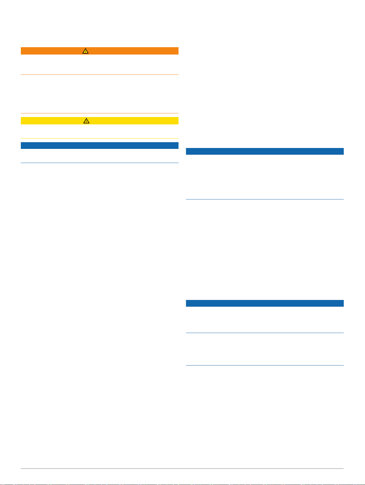
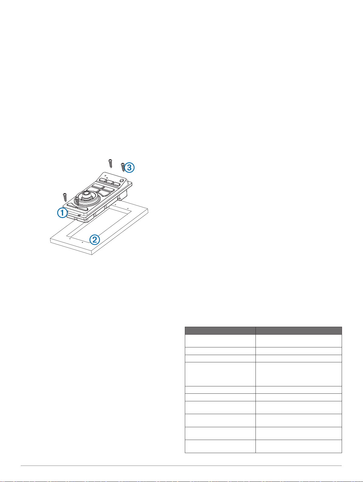
After the device À fits correctly in the cutout, make sure the
7
mounting holes on the device line up with the pilot holes Á on
the template.
If the mounting holes on the device do not line up, mark the
8
new pilot-hole locations.
Using either a 3/32 in. (2.5 mm) drill bit, or drill bit appropriate
9
for the mounting surface, drill the pilot holes.
Remove the template from the mounting surface.
10
If you will not have access to the back of the device after you
11
mount it, connect all necessary cables to the device before
placing it into the cutout.
Place the device into the cutout.
12
Secure the device to the mounting surface using the included
13
screws Â.
Install the decorative bezel by snapping it in place around the
14
edges of the device.
Connection and Cable Considerations
• For easier cable routing, the power and Garmin Marine
Network cables are packaged without the locking rings
installed. You should route the cables before you install the
locking rings.
• After connecting a locking ring to a cable, you should make
sure the locking ring is securely connected and the o-ring is
in place so the power or data connection remains secure.
• The device should be connected to the same power source
as the other devices on the same Garmin Marine Network. If
this is not possible, all the devices must be connected to the
same ground.
Connecting the GRID™ to the Garmin Marine Network
The GRID is not compatible with Garmin chartplotters prior to
the GPSMAP® 8000 Series and the GPSMAP 8500.
The GRID does not need to be connected directly to the device
that you plan to control with the GRID. It can be assigned to any
compatible device connected to the same Garmin Marine
Network.
Connect the GRID to a Garmin device on the Garmin Marine
1
Network using a Garmin Marine Network cable.
After the rest of the devices in your Garmin Marine Network
2
are installed, use the software to assign the GRID to a
compatible Garmin device.
You can initiate the paring of the devices from the chartplotter or
from the GRID remote input device.
Pairing the GRID Device with the Chartplotter from the GRID Device
On the GRID remote input device, press + and HOME at the
1
same time.
A selection page opens on all of the chartplotters on the
Garmin Marine Network.
Rotate the wheel on the GRID remote input device to
2
highlight Select on the chartplotter you want to control with
the GRID remote input device.
Press SELECT.
3
Pairing the GRID Device with the Chartplotter from the Chartplotter
Select Settings > System > Station Information > GRID™
1
Pairing > Add.
On the GRID remote input device, press SELECT.
2
Rotating the GRID Joystick
For certain installation situations, you can rotate the orientation
of the GRID joystick.
Select Settings > Communications > Marine Network.
1
Select the GRID device.
2
GRID Specifications
Specification Measurement
Dimensions (W×H×D) 31/16 × 67/8 × 23/8 in. (77 × 174.8 × 60
Weight 9.1 oz. (258 g)
Temperature range From 5° to 158°F (from -15° to 70°C)
Material Fully gasketed, high-impact plastic,
Input power 10–35 Vdc
Fuse 7.5 A, 42 V fast-acting
Max. power usage at 10
Vdc
Typical current draw at 12
Vdc
Max. current draw at 12
Vdc
Compass-safe distance 14 in. (356 mm)
mm)
waterproof to IEC 60529 IPX7 standards
2.8 W
100 mA
280 mA
Pairing the GRID Remote Input Device with the Chartplotter
Before you can use a GRID remote input device with a
chartplotter, you must pair the devices.
Installation Instructions 3

GRID™ Instructions d'installation
Informations importantes relatives à la sécurité
AVERTISSEMENT
Consultez le guide Informations importantes sur le produit et la
sécurité inclus dans l'emballage du produit pour prendre
connaissance des avertissements et autres informations sur le
produit.
Lorsque vous connectez le câble d'alimentation, ne retirez pas
le porte-fusible en ligne. Pour éviter de vous blesser ou
d'endommager le produit en l'exposant au feu ou à une chaleur
extrême, le fusible approprié doit être placé comme indiqué
dans les caractéristiques techniques du produit. De plus, la
connexion du câble d'alimentation en l'absence du fusible
approprié annule la garantie du produit.
ATTENTION
Portez toujours des lunettes de protection, un équipement
antibruit et un masque anti-poussière lorsque vous percez,
coupez ou poncez.
AVIS
Lorsque vous percez ou coupez, commencez toujours par
vérifier la nature de la face opposée de l'élément.
Pour obtenir des performances optimales et éviter toute
détérioration du bateau, installez l'appareil selon les instructions
suivantes.
Lisez toutes les instructions d'installation avant de procéder à
l'installation. Si vous rencontrez des difficultés durant
l'installation, contactez le service d'assistance produit de
Garmin.
Enregistrement de l'appareil
Aidez-nous à mieux vous servir en remplissant dès aujourd'hui
notre formulaire d'enregistrement en ligne.
• Rendez-vous sur le site http://my.garmin.com.
• Conservez en lieu sûr l'original de la facture ou une
photocopie.
Contacter l'assistance produit Garmin
• Rendez-vous sur le site www.garmin.com/support pour
obtenir une assistance par pays.
• Aux Etats-Unis, appelez le 913-397-8200 ou le
1-800-800-1020.
• Au Royaume-Uni, appelez le 0808 238 0000.
• En Europe, appelez le +44 (0) 870 850 1241.
Mise à jour du logiciel
Vous devrez peut-être mettre à jour le logiciel de l'appareil
lorsque vous l'installerez ou que vous ajouterez un accessoire.
Chargement du nouveau logiciel sur une carte mémoire
Insérez une carte mémoire dans le lecteur de carte SD de
1
l'ordinateur.
Visitez le site www.garmin.com/support/software/marine.html.
2
Sélectionnez Télécharger en regard de GPSMAP Series
3
avec carte SD.
Lisez et approuvez les conditions.
4
Sélectionnez Télécharger.
5
Sélectionnez Exécuter.
6
Sélectionnez le lecteur associé à la carte mémoire puis
7
sélectionnez Suivant > Terminer.
Mise à jour du logiciel de l'appareil
Afin de pouvoir mettre à jour le logiciel, vous devez vous
procurer une carte mémoire de mise à jour logicielle ou charger
la dernière version du logiciel sur une carte mémoire.
Mettez le traceur sous tension.
1
Lorsque l'écran d'accueil apparaît, insérez la carte mémoire
2
dans le lecteur de carte mémoire.
REMARQUE : pour que les instructions de mise à jour du
logiciel apparaissent, l'appareil doit avoir été complètement
démarré avant que la carte ne soit insérée.
Suivez les instructions présentées à l'écran.
3
Patientez quelques minutes le temps que la procédure de
4
mise à jour du logiciel s'exécute.
Lorsque vous y êtes invité, laissez la carte mémoire en place
5
et redémarrez le traceur manuellement.
Retirez la carte mémoire.
6
REMARQUE : si la carte mémoire est retirée avant que
l'appareil ne redémarre complètement, la mise à jour du
logiciel n'est pas terminée.
Outils requis
• Perceuse et forets
• Tournevis cruciforme numéro 2
• Scie sauteuse ou foreuse rotative
• Lime et papier de verre
• Mastic d'étanchéité (facultatif)
Considérations relatives au montage
AVIS
Installez cet appareil à un emplacement qui n'est pas exposé à
des températures ou des conditions extrêmes. La plage de
températures pour cet appareil est indiquée dans les
caractéristiques techniques du produit. Une exposition
prolongée à des températures dépassant la plage de
températures spécifiée, pendant le stockage ou en cours de
fonctionnement, peut provoquer une panne de l'appareil. Les
dommages dus aux températures extrêmes et leurs
conséquences ne sont pas couverts par la garantie.
Cet appareil peut être installé sur le tableau de bord ou tout
autre support au moyen du matériel fourni. Lorsque vous
sélectionnez un emplacement de montage, tenez compte des
considérations suivantes.
• L'appareil doit être installé à un emplacement accessible.
Vous devez pouvoir accéder facilement à la manette et aux
boutons afin interagir avec l'appareil de navigation affecté.
• Pour éviter toute interférence avec un compas magnétique,
l'appareil doit être installé à la distance de sécurité au
compas indiquée dans les caractéristiques techniques du
produit.
• L'emplacement doit permettre la connexion des câbles.
Installation de l'appareil
AVIS
Faites attention lorsque vous percez le trou pour encastrer
l'appareil. Le dégagement entre le boîtier et les trous de fixation
est très réduit et en perçant un trou trop grand, vous risquez de
compromettre la stabilité de l'appareil après son installation.
Si vous montez le support de montage sur de la fibre de verre
avec des vis, nous vous recommandons d'utiliser un foret de
fraisage pour percer un trou à fond plat à travers le revêtement
de la couche supérieure. De cette manière, vous ne risquez pas
de fissurer le revêtement au moment du serrage des vis.
4 Instructions d'installation

Vous pouvez utiliser le modèle et le matériel fournis pour
installer l'appareil à l'emplacement choisi.
Découpez le modèle de montage encastré et assurez-vous
1
qu'il est adapté à l'emplacement de montage de l'appareil.
Retirez la protection de la partie adhésive au dos du modèle
2
et appliquez le modèle à l'emplacement de montage de
l'appareil.
A l'aide d'un foret 7/16 po (11 mm), percez un ou plusieurs
3
trous aux angles formés par la ligne continue du modèle afin
de préparer le support de montage pour la découpe.
A l'aide d'une scie sauteuse, découpez le support de
4
montage le long du côté intérieur de la ligne continue du
modèle.
Placez l'appareil dans la découpe pour vérifier l'ajustement.
5
Au besoin, utilisez une lime et du papier de verre pour affiner
6
le contour de la découpe.
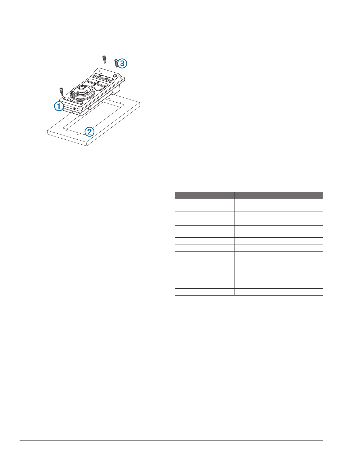
Lorsque l'appareil À est bien ajusté au contour, assurez-vous
7
que les trous de montage sur l'appareil s'alignent sur les
trous d'implantation Á sur le modèle.
Si les trous de montage sur l'appareil ne sont pas alignés,
8
repérez les nouveaux emplacements des trous
d'implantation.
A l'aide d'un foret 3/32 po (2,5 mm) ou d'un foret adapté au
9
support de montage, percez les trous d'implantation.
Retirez le modèle du support de montage.
10
Si vous n'avez pas accès à l'arrière de l'appareil après son
11
montage, raccordez tous les câbles nécessaires à l'appareil
avant de le placer dans la découpe.
Placez l'appareil dans la découpe.
12
Fixez l'appareil au support de montage à l'aide des vis
13
fournies Â.
Installez le cadre de décoration autour de l'appareil.
14
Considérations relatives aux connexions et aux câbles
• Afin de faciliter leur mise en place, les câbles d'alimentation
et les câbles du réseau Garmin Marine Network sont
conditionnés sans anneau de verrouillage. Acheminez les
câbles avant d'installer les anneaux de verrouillage.
• Après avoir installé un anneau de verrouillage sur un câble,
assurez-vous que l'anneau est solidement fixé et que le joint
torique est en place de manière à sécuriser la connexion
(alimentation ou données).
• L'appareil doit être raccordé à la même source d'alimentation
que les autres appareils utilisant le même réseau Garmin
Marine Network. Si ce n'est pas possible, tous les appareils
doivent être connectés à la même masse.
Connexion du GRID au réseau Garmin Marine Network
Le GRID n'est pas compatible avec les traceurs Garmin
antérieurs aux GPSMAP série 8000 et au GPSMAP 8500.
Le GRID n'a pas besoin d'être connecté directement à l'appareil
que vous envisagez de contrôler à l'aide du GRID. Il peut être
affecté à n'importe quel appareil compatible connecté au même
réseau Garmin Marine Network.
Connectez le GRID à un appareil Garmin du réseau Garmin
1
Marine Network à l'aide d'un câble Garmin Marine Network.
Une fois les autres appareils du réseau Garmin Marine
2
Network installés, utilisez le logiciel pour affecter le GRID à
un appareil Garmin compatible.
Couplage du périphérique de contrôle à distance GRID avec le traceur
Avant de pouvoir utiliser un périphérique de contrôle à distance
GRID avec un traceur, vous devez le coupler avec l'appareil.
Vous pouvez lancer le couplage des appareils depuis le traceur
ou depuis le périphérique de contrôle à distance GRID.
Couplage du périphérique GRID avec le traceur à partir du périphérique GRID
Sur le périphérique de contrôle à distance GRID, appuyez en
1
même temps sur les boutons + et HOME.
Une page de sélection s'ouvre sur tous les traceurs du
réseau Garmin Marine Network.
Faites tourner la roue du périphérique de contrôle à distance
2
GRID jusqu'à atteindre Sélect. sur le traceur que vous
souhaitez contrôler à l'aide du GRID.
Appuyez sur SELECT.
3
Couplage du périphérique GRID avec le traceur à partir du traceur
Sélectionnez Paramètres > Système > Informations de
1
station > Couplage GRID™ > Ajouter.
Sur le périphérique de contrôle à distance GRID, appuyez
2
sur le bouton SELECT.
Utilisation du joystick GRID
Dans certaines situations d'installation, vous pouvez faire pivoter
l'orientation du joystick GRID.
Sélectionnez Paramètres > Communications > Réseau
1
marin.
Sélectionnez l'appareil GRID.
2
Caractéristiques de la grille
Caractéristique Mesure
Dimensions (L × H × P) 31/16 × 67/8 x 23/8 po (77 × 174,8 ×
Poids 9,1 onces (258 g)
Plage de températures De 5 °F à 158 °F (de -15 °C à 70 °C)
Matériau Hermétiquement fermé, en plastique
Puissance d'entrée 10–35 V c.c.
Fusible 7,5 A, 42 V rapide
Consommation max. à 10
V c.c.
Intensité typique à 12 V c.c. 100 mA
Intensité maximum à 12
V c.c.
Distance de sécurité au
compas
60 mm)
résistant aux chocs, étanche conformément aux normes IEC 60529 IPX7
2,8 W
280 mA
14 po (356 mm)
Instructions d'installation 5

GRID™ Istruzioni di installazione
Informazioni importanti sulla sicurezza
AVVERTENZA
Per avvisi sul prodotto e altre informazioni importanti, vedere la
guida Informazioni importanti sulla sicurezza e sul prodotto
inclusa nella confezione.
Quando si collega il cavo di alimentazione, non rimuovere il
portafusibili. Per evitare possibili lesioni o danni al prodotto
dovuti a incendio o surriscaldamento, è necessario che il fusibile
appropriato sia installato come indicato nelle specifiche del
prodotto. Inoltre, il collegamento del cavo di alimentazione
senza che sia installato il fusibile appropriato invalida la
garanzia del prodotto.
ATTENZIONE
Durante le operazioni di foratura, taglio o carteggiatura,
indossare degli occhiali protettivi, una maschera antipolvere e
un'adeguata protezione per l'udito.
AVVISO
Prima di effettuare fori o tagli verificare l'eventuale presenza di
oggetti nel lato opposto della superficie da tagliare.
Per ottenere le massime prestazioni ed evitare danni
all'imbarcazione, installare il dispositivo attenendosi alle
istruzioni riportate di seguito.
Prima di procedere all'installazione, leggere attentamente le
istruzioni. In caso di difficoltà durante l'installazione, contattare il
servizio di assistenza ai prodotti di Garmin.
Registrazione del dispositivo
Per un'assistenza completa, eseguire subito la registrazione
online.
• Visitare il sito Web http://my.garmin.com.
• Conservare in un luogo sicuro la ricevuta di acquisto originale
o una fotocopia.
Contattare il servizio di assistenza Garmin
• Per informazioni sull'assistenza nel Paese di residenza,
visitare il sito Web www.garmin.com/support.
• Negli Stati Uniti, chiamare il numero 913-397-8200 o
1-800-800-1020.
• Nel Regno Unito, chiamare il numero 0808 238 0000.
• In Europa, chiamare il numero +44 (0) 870 850 1241.
Aggiornamento software
All'atto dell'installazione o aggiungendo un accessorio al sistema
esistente, potrebbe essere necessario dover aggiornare il
software del prodotto.
Caricamento del nuovo software su una scheda di memoria
Inserire una scheda di memoria nel relativo alloggiamento sul
1
computer.
Visitare il sito Web www.garmin.com/support/software/marine
2
.html.
Selezionare Download accanto a Serie GPSMAP con
3
scheda SD.
Leggere e accettare i termini.
4
Selezionare Download.
5
Selezionare Corsa.
6
Selezionare l'unità associata alla scheda di memoria, quindi
7
selezionare Successivo > Fine.
Aggiornamento del software del dispositivo
Per poter aggiornare il software, è necessario utilizzare una
scheda d'aggiornamento software o caricare l'ultima versione
software su una scheda di memoria.
Accendere il chartplotter.
1
Una volta visualizzata la schermata principale, inserire la
2
cartuccia d'aggiornamento del lettore cartografico.
NOTA: per poter visualizzare le istruzioni di aggiornamento
del software, è necessario avviare il dispositivo
completamente prima di inserire la scheda.
Seguire le istruzioni visualizzate sullo schermo.
3
Attendere qualche minuto che il processo di aggiornamento
4
software sia completato.
Quando richiesto, lasciare inserita la scheda di memoria e
5
riavviare manualmente il chartplotter.
Rimuovere la scheda di memoria.
6
NOTA: se la cartuccia d'aggiornamento viene rimossa prima
del riavvio completo del dispositivo, l'aggiornamento software
non viene completato.
Strumenti necessari per l'installazione
• Trapano e punte da trapano
• Cacciavite a croce 2
• Sega o strumento a rotazione
• Lima e carta abrasiva
• Sigillante marino (opzionale)
Considerazioni sull'installazione
AVVISO
Non installare il dispositivo in una posizione soggetta a
temperature o condizioni estreme. L'intervallo di temperature per
il dispositivo è indicato nelle specifiche del prodotto.
L'esposizione prolungata a temperature che superano l'intervallo
di temperature specificato, in condizioni di stoccaggio o di
operatività, può causare danni al dispositivo. I danni e le
conseguenze correlate all'esposizione a temperature estreme
non sono coperti dalla garanzia.
Questo dispositivo può essere montato sul cruscotto o su altre
superfici utilizzando gli accessori di installazione inclusi.
Scegliere la posizione di montaggio tenendo presente quanto
segue.
• Il dispositivo deve essere installato in una posizione
facilmente accessibile. È necessario poter accedere al
joystick e ai pulsanti in tempi rapidi, per poter interagire con il
relativo dispositivo di navigazione.
• Per evitare interferenze con una bussola magnetica,
installare il dispositivo rispettando la distanza di sicurezza
dalla bussola indicata nelle specifiche del prodotto.
• Lasciare spazio sufficiente per l'inserimento e il collegamento
dei cavi.
Installazione dell'unità
AVVISO
Prestare attenzione durante il taglio del foro per effettuare
l'installazione a incasso del dispositivo. Tra la scocca e i fori di
installazione l'ingombro è minimo, pertanto il taglio di un foro
troppo grande può compromettere la stabilità del dispositivo
dopo l'installazione.
Se si sta installando la staffa su fibra di vetro con delle viti, si
consiglia di utilizzare una punta fresatrice per praticare una
svasatura attraverso lo strato di resina. In questo modo è
possibile evitare crepe prodotte dal serraggio delle viti nello
strato di resina.
La dima e gli accessori per l'installazione inclusi possono essere
utilizzati per montare il dispositivo nella posizione scelta.
Rifinire la dima per il montaggio a incasso e verificare che sia
1
idonea per la posizione scelta per l'installazione.
6 Istruzioni di installazione
Rimuovere la pellicola protettiva dal retro della dima e
2
attaccare la dima nella posizione prestabilita.
Con una punta da trapano da 7/16 poll. (11 mm) praticare uno
3
o più fori all'interno degli angoli della linea sulla dima e
preparare la superficie di montaggio per il taglio.
Tagliare con una sega la superficie di montaggio seguendo
4
l'interno della linea tracciata sulla dima.
Posizionare il dispositivo nel foro per verificare l'ingombro.
5
Se necessario, utilizzare una lima e della carta abrasiva per
6
rifinire l'incasso.
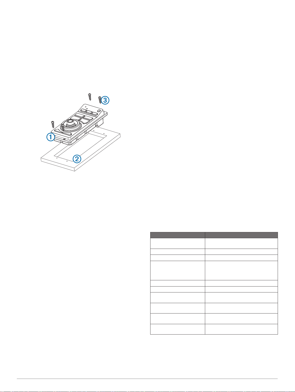
Dopo aver inserito correttamente il dispositivo À nell'incasso,
7
accertarsi che i fori di montaggio sul dispositivo siano allineati
ai fori di riferimento Á sulla dima.
Qualora non lo fossero, segnare le nuove posizioni.
8
Utilizzando un punta da trapano da 3/32 poll. (2,5 mm) o una
9
punta adatta alla superficie di montaggio, praticare i fori di
riferimento.
Rimuovere la dima dalla superficie di montaggio.
10
Se il foro d'incasso non permette il collegamento dei cavi con
11
il dispositivo installato, collegare tutti i cavi necessari prima di
posizionarlo.
Posizionare il dispositivo nell'incasso.
12
Fissare il dispositivo alla superficie di montaggio utilizzando
13
le viti in dotazione Â.
Installare la ghiera decorativa facendola scattare in posizione
14
lungo i bordi del dispositivo.
Considerazioni sui cavi e i collegamenti
• Per un passaggio dei cavi semplificato, il cavo di
alimentazione e il cavo Garmin Marine Network vengono
forniti senza le ghiere di chiusura installate. Passare i cavi
prima di installare le ghiere di chiusura.
• Dopo aver installato una ghiera di chiusura sul cavo,
accertarsi che questa sia collegata saldamente e che l'anello
circolare sia in posizione, affinché l'alimentazione e la
connessione dati siano ottimali.
• Il dispositivo deve essere collegato alla stessa sorgente di
alimentazione dei dispositivi connessi alla stessa Garmin
Marine Network. Se ciò non fosse possibile, tutti i dispositivi
devono essere collegati alla stessa massa.
Connessione del GRID alla Garmin Marine Network
Il GRID non è compatibile con i chartplotter Garmin precedenti
alle versioni GPSMAP serie 8000 e GPSMAP 8500.
Non è necessario collegare il GRID direttamente al dispositivo
da controllare con il GRID, ma può essere assegnato a qualsiasi
dispositivo compatibile connesso alla stessa Garmin Marine
Network.
Collegare il GRID a un dispositivo Garmin sulla Garmin
1
Marine Network utilizzando un cavo Garmin Marine Network.
Dopo aver installato tutti gli altri dispositivi connessi alla
2
Garmin Marine Network, utilizzare il software per assegnare il
GRID a un dispositivo Garmin compatibile.
Associazione del dispositivo di comando a distanza GRID al chartplotter
Prima di poter utilizzare un dispositivo di comando a distanza
GRID con un chartplotter, è necessario associare i dispositivi.
È possibile avviare l'associazione dei dispositivo dal chartplotter
o dal dispositivo di comando a distanza GRID.
Associazione del dispositivo GRID al chartplotter dal dispositivo GRID
Sul dispositivo di comando a distanza GRID, premere il tasto
1
+ e HOME contemporaneamente.
Si apre una pagina di selezione su tutti i chartplotter sulla
Garmin Marine Network.
Ruotare la ghiera sul dispositivo di comando a distanza GRID
2
per evidenziare Selez. sul chartplotter che si intende
controllare con il dispositivo di comando a distanza GRID.
Premere SELECT.
3
Associazione del dispositivo GRID al chartplotter dal chartplotter
Selezionare Impostazioni > Sistema > Informazioni sulla
1
stazione > Associazione GRID™ > Aggiungi.
Sul dispositivo di comando a distanza GRID, premere
2
SELECT.
Rotazione del joystick GRID
In alcune situazioni di installazione, è possibile ruotare
l'orientamento del joystick GRID.
Selezionare Impostazioni > Comunicazioni > Marine
1
Network.
Selezionare il dispositivo GRID.
2
Specifiche del GRID
Specifiche Misure
Dimensioni (L×A×P) 31/16 × 67/8 × 23/8 poll. (77 × 174,8 × 60
Peso 9,1 once (258 g)
Temperatura operativa Da 5° a 158°F (da -15° a 70°C)
Materiale Completamente stagno, in plastica a
Tensione in ingresso 10–35 V cc
Fusibile 7,5 A, 42 V ad azione rapida
Consumo energetico max a
10 V cc
Assorbimento di corrente
tipico a 12 V cc
Assorbimento di corrente max
a 12 V cc
Distanza di sicurezza dalla
bussola
mm)
elevata resistenza, impermeabile in
conformità agli standard IEC 60529
IPX7
2,8 W
100 mA
280 mA
14 poll. (356 mm)
Istruzioni di installazione 7

GRID™ Installationsanweisungen
Wichtige Sicherheitsinformationen
WARNUNG
Lesen Sie alle Produktwarnungen und sonstigen wichtigen
Informationen in der Anleitung "Wichtige Sicherheits- und
Produktinformationen", die dem Produkt beiliegt.
Wenn Sie das Netzkabel anschließen, entfernen Sie nicht den
leitungsinternen Sicherungshalter. Vermeiden Sie mögliche
Verletzungen oder Produktschäden durch Feuer oder
Überhitzung, indem Sie darauf achten, dass die richtige
Sicherung eingesetzt ist (siehe technische Daten zum Produkt).
Darüber hinaus erlischt die Garantie des Produkts, wenn Sie
das Netzkabel anschließen und nicht die richtige Sicherung
eingesetzt ist.
ACHTUNG
Tragen Sie beim Bohren, Schneiden und Schleifen immer
Schutzbrille, Gehörschutz und eine Staubschutzmaske.
HINWEIS
Prüfen Sie beim Bohren oder Schneiden stets die andere Seite
der zu bearbeitenden Fläche.
Halten Sie sich beim Einbau des Geräts an diese Anweisungen,
um die bestmögliche Leistung zu erzielen und eine
Beschädigung des Boots zu vermeiden.
Lesen Sie die gesamten Installationsanweisungen, bevor Sie mit
der Installation beginnen. Sollten bei der Installation Probleme
auftreten, wenden Sie sich an den Support von Garmin.
Registrieren des Geräts
Helfen Sie uns, unseren Service weiter zu verbessern, und
füllen Sie die Online-Registrierung noch heute aus.
• Rufen Sie die Website http://my.garmin.com auf.
• Bewahren Sie die Originalquittung oder eine Fotokopie an
einem sicheren Ort auf.
Kontaktaufnahme mit dem Support von Garmin
• Rufen Sie die Website www.garmin.com/support auf, um
Informationen zum Support in den einzelnen Ländern zu
erhalten.
• Nutzen Sie als Kunde in den USA die Rufnummern
+1-913-397-8200 oder +1-800-800-1020.
• Nutzen Sie als Kunde in Großbritannien die Rufnummer
0808 238 0000.
• Nutzen Sie als Kunde in Europa die Rufnummer
+44 (0) 870 850 1241.
Software-Update
Möglicherweise müssen Sie die Gerätesoftware aktualisieren,
wenn Sie das Gerät installieren oder Zubehör hinzufügen.
Laden der neuen Software auf eine Speicherkarte
Legen Sie eine Speicherkarte in den Kartensteckplatz des
1
Computers ein.
Rufen Sie die Website www.garmin.com/support/software
2
/marine.html auf.
Wählen Sie neben GPSMAP Serie mit SD-Speicherkarte
3
die Option Herunterladen.
Lesen Sie die Bedingungen, und stimmen Sie ihnen zu.
4
Wählen Sie Herunterladen.
5
Wählen Sie Laufen.
6
Wählen Sie das Laufwerk, das mit der Speicherkarte
7
verbunden ist, und wählen Sie Weiter > Fertigstellen.
Aktualisieren der Gerätesoftware
Bevor Sie die Software aktualisieren können, benötigen Sie eine
Speicherkarte für Software-Updates oder müssen die aktuelle
Software auf eine Speicherkarte laden.
Schalten Sie den Kartenplotter ein.
1
Wenn das Hauptmenü angezeigt wird, legen Sie die
2
Speicherkarte in den Kartensteckplatz ein.
HINWEIS: Damit die Anweisungen für das Software-Update
angezeigt werden, muss das Gerät vollständig hochgefahren
sein, bevor Sie die Karte einlegen.
Folgen Sie den Anweisungen auf dem Display.
3
Das Software-Update kann mehrere Minuten in Anspruch
4
nehmen.
Lassen Sie bei der Aufforderung die Speicherkarte eingelegt,
5
und starten Sie den Kartenplotter manuell neu.
Entfernen Sie die Speicherkarte.
6
HINWEIS: Falls die Speicherkarte vor dem vollständigen
Neustart des Geräts entnommen wird, kann das SoftwareUpdate nicht abgeschlossen werden.
Erforderliches Werkzeug
• Bohrmaschine und Bohrer
• Kreuzschlitzschraubendreher Nr. 2
• Stichsäge oder Multifunktionswerkzeug
• Feile und Sandpapier
• Seewassertaugliches Dichtungsmittel (optional)
Hinweise zur Montage
HINWEIS
Montieren Sie das Gerät an einem Ort, an dem es keinen
extremen Temperaturen oder Umweltbedingungen ausgesetzt
ist. Der Temperaturbereich für dieses Gerät ist in den
technischen Daten zum Produkt aufgeführt. Eine längere
Lagerung oder ein längerer Betrieb bei Temperaturen über dem
angegebenen Temperaturbereich kann zu einem Versagen des
Geräts führen. Schäden durch extreme Temperaturen und
daraus resultierende Folgen sind nicht von der Garantie
abgedeckt.
Das Gerät kann unter Verwendung der mitgelieferten
Montageteile im Armaturenbrett oder in einer anderen
Oberfläche montiert werden. Beachten Sie bei der Auswahl
eines Montageorts folgende Hinweise.
• Das Gerät sollte so montiert werden, dass es leicht
zugänglich ist. Sie müssen problemlos auf den Joystick und
die Tasten zugreifen können, sodass eine Interaktion mit
dem zugewiesenen Navigationsgerät möglich ist.
• Damit es nicht zu Störungen mit Magnetkompassen kommt,
muss bei der Montage des Geräts der in den technischen
Daten zum Produkt aufgeführte Sicherheitsabstand zum
Kompass eingehalten werden.
• Der Montageort muss ausreichend Platz für die Verlegung
und den Anschluss der Kabel bieten.
Anbringen des Geräts
HINWEIS
Gehen Sie beim Schneiden des Ausschnitts für die bündige
Montage des Geräts vorsichtig vor. Zwischen Gehäuse und
Montagelöchern besteht nur ein geringer Abstand. Wird der
Ausschnitt zu groß geschnitten, könnte die Stabilität des Geräts
nach der Montage beeinträchtigt sein.
Wenn Sie die Halterung in Glasfasermaterial einlassen und
festschrauben, wird die Verwendung eines Senkkopfbohrers
empfohlen, um die Ansenkung nur durch die oberste Gelcoat-
8 Installationsanweisungen
Schicht zu bohren. Dadurch wird Rissen in der obersten
Gelschicht beim Anziehen der Schrauben vorgebeugt.
Die Schablone und Montageteile aus dem Lieferumfang können
für die Montage des Geräts am gewählten Ort verwendet
werden.
Schneiden Sie die Schablone für die bündige Montage zu,
1
und achten Sie darauf, dass sie auf die Fläche passt, an der
das Gerät montiert werden soll.
Entfernen Sie die Schutzfolie von der Rückseite der
2
Schablone, und bringen Sie die Schablone auf der Fläche an,
an der das Gerät montiert werden soll.
Bringen Sie mit einem Bohrer von 7/16 Zoll (11 mm) eine oder
3
mehrere der Bohrungen an den Ecken der durchgängigen
Linie auf der Schablone an, um die Montagefläche für das
Schneiden vorzubreiten.
Schneiden Sie mit einer Stichsäge die Montagefläche entlang
4
der Innenseite der durchgehenden Schablonenlinie aus.
Setzen Sie das Gerät in den Ausschnitt ein, um seinen Sitz
5
zu testen.
Passen Sie den Durchmesser des Ausschnitts bei Bedarf mit
6
Feile und Sandpapier an.
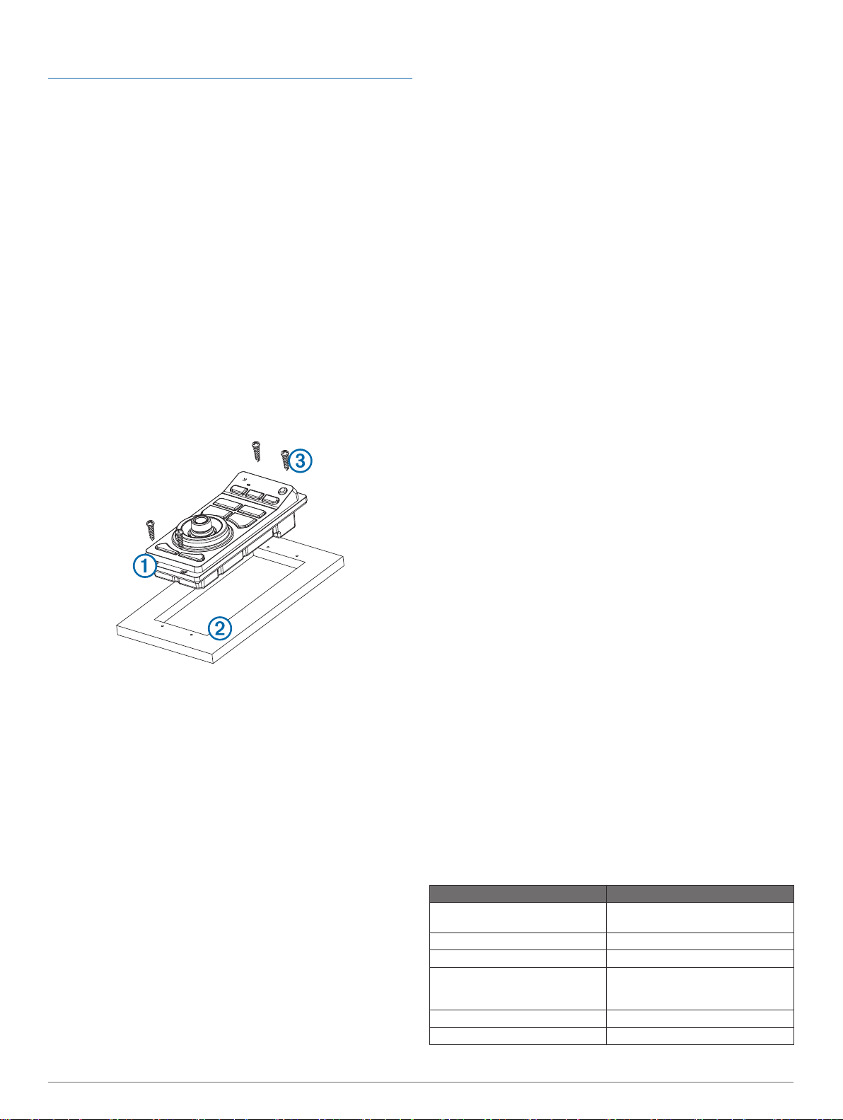
Wenn das Gerät À ordnungsgemäß im Ausschnitt sitzt,
7
vergewissern Sie sich, dass die Montagelöcher am Gerät auf
die Vorbohrungen Á der Schablone ausgerichtet sind.
Ist das nicht der Fall, kennzeichnen Sie neue Positionen für
8
die Vorbohrungen.
Verwenden Sie entweder einen Bohrer von 3/32 Zoll (2,5 mm)
9
oder einen Bohrer, der für die Montagefläche geeignet ist, um
die Vorbohrungen anzubringen.
Entfernen Sie die Schablone von der Montagefläche.
10
Wenn Sie nach der Montage des Geräts keinen Zugang zur
11
Rückseite des Geräts mehr haben, schließen Sie alle
erforderlichen Kabel an, bevor Sie das Gerät in den
Ausschnitt einsetzen.
Setzen Sie das Gerät in den Ausschnitt ein.
12
Sichern Sie das Gerät mit den mitgelieferten Schrauben  an
13
der Montagefläche.
Montieren Sie die Verkleidung, indem Sie sie an den Ecken
14
des Geräts einrasten lassen.
Hinweise zu Verbindungen und Verkabelung
• Zur Vereinfachung der Kabelführung sind die Netzkabel und
Garmin Marinenetzwerkkabel ohne installierte
Sicherungsringe verpackt. Sie sollten die Kabel verlegen,
bevor Sie die Sicherungsringe installieren.
• Nachdem Sie einen Sicherungsring mit einem Kabel
verbunden haben, sollten Sie sich vergewissern, dass der
Sicherungsring sicher verbunden und der Dichtungsring
richtig positioniert ist, damit die Strom- oder Datenverbindung
sicher ist.
• Das Gerät sollte an dieselbe Stromversorgung
angeschlossen werden wie andere Geräte im gleichen
Garmin Marinenetzwerk. Falls dies nicht möglich ist, müssen
alle Geräte an die gleiche Masse angeschlossen werden.
Anschließen des GRID an das Garmin Marinenetzwerk
Der GRID ist nicht mit Garmin Kartenplottern vor der Serie
GPSMAP 8000 und vor dem GPSMAP 8500 kompatibel.
Der GRID muss nicht direkt mit dem Gerät verbunden werden,
das Sie mit dem GRID steuern möchten. Es kann allen
kompatiblen Geräten zugewiesen werden, die mit demselben
Garmin Marinenetzwerk verbunden sind.
Schließen Sie den GRID an ein Garmin Gerät im Garmin
1
Marinenetzwerk an. Verwenden Sie dazu ein Garmin
Marinenetzwerkkabel.
Nachdem die übrigen Geräte des Garmin Marinenetzwerks
2
installiert sind, weisen Sie dem GRID über die Software ein
kompatibles Garmin Gerät zu.
Koppeln der GRID Fernbedienung mit dem Kartenplotter
Zum Verwenden einer GRID Fernbedienung mit einem
Kartenplotter müssen Sie die Geräte koppeln.
Sie können die Kopplung der Geräte über den Kartenplotter
oder die GRID Fernbedienung initiieren.
Koppeln des GRID Geräts mit dem Kartenplotter über das GRID Gerät
Drücken Sie auf der GRID Fernbedienung gleichzeitig die
1
Tasten + und HOME.
Auf allen Kartenplottern im Garmin Marinenetzwerk wird eine
Auswahlseite angezeigt.
Drehen Sie das Rad an der GRID Fernbedienung, um auf
2
dem Kartenplotter, den Sie mit der GRID Fernbedienung
bedienen möchten, die Option Wählen auszuwählen.
Drücken Sie die Taste SELECT.
3
Koppeln des GRID Geräts mit dem Kartenplotter über den Kartenplotter
Wählen Sie Einstellungen > System >
1
Stationsinformationen > GRID™-Kopplung > Hinzufügen.
Drücken Sie auf der GRID Fernbedienung die Taste
2
SELECT.
Drehen des GRID Joysticks
Für bestimmte Situationen können Sie die Ausrichtung des
GRID Joysticks drehen.
Wählen Sie Einstellungen > Kommunikationsdienste >
1
Marinenetzwerk.
Wählen Sie das GRID aus.
2
Technische Daten: GRID
Angabe Werte
Abmessungen (B × H × T) 3 1/16 × 6 7/8 × 2 3/8 Zoll (77 ×
Gewicht 9,1 Unzen (258 g)
Temperaturbereich 5 °F bis 158 °F ( -15 °C bis 70 °C)
Material Vollständig abgedichtet, schlag-
Leistungsaufnahme 10 bis 35 V Gleichspannung
Sicherung 7,5 A, 42 V, flink
174,8 × 60 mm)
fester Kunststoff, wasserdicht
gemäß IEC 60529 IPX7
Installationsanweisungen 9

Angabe Werte
Maximale Leistungsaufnahme bei
10 V Gleichspannung
Typische Stromaufnahme bei
12 V Gleichspannung
Maximale Stromaufnahme bei
12 V Gleichspannung
Sicherheitsabstand zum
Kompass
2,8 W
100 mA
280 mA
14 Zoll (356 mm)
10 Installationsanweisungen
GRID™ Instrucciones de instalación
Información importante sobre seguridad
ADVERTENCIA
Consulta la guía Información importante sobre el producto y tu
seguridad que se incluye en la caja del producto y en la que
encontrarás avisos e información importante sobre el producto.
Al conectar el cable de alimentación, no retires el portafusibles
en línea. Para evitar la posibilidad de causar daños personales
o daños al producto provocados por el fuego o un
sobrecalentamiento, debe colocarse el fusible adecuado tal y
como se indica en las especificaciones del producto. Además, la
conexión del cable de alimentación sin el fusible adecuado
anulará la garantía del producto.
Cuando aparezca la pantalla de inicio, introduce la tarjeta de
2
memoria en la ranura para tarjetas.
NOTA: para que aparezcan las instrucciones de
actualización del software, el dispositivo debe haberse
iniciado completamente antes de introducir la tarjeta.
Sigue las instrucciones que se muestran en la pantalla.
3
Espera unos minutos a que se complete el proceso de
4
actualización del software.
Cuando se indique, coloca la tarjeta de memoria en su sitio y
5
reinicia el plotter manualmente.
Extrae la tarjeta de memoria.
6
NOTA: si se extrae la tarjeta de memoria antes de que el
dispositivo se reinicie por completo, la actualización de
software no se completará.
ATENCIÓN
Utiliza siempre gafas de seguridad, un protector de oídos y una
máscara antipolvo cuando vayas a realizar orificios, cortes o
lijados.
AVISO
Al realizar orificios o cortes, comprueba siempre lo que hay al
otro lado de la superficie.
Para obtener un rendimiento óptimo y evitar daños en la
embarcación, instala el transductor de acuerdo con estas
instrucciones.
Lee todas las instrucciones de instalación antes de proceder a
la misma. Si tienes dificultades con la instalación, ponte en
contacto con el departamento de asistencia de Garmin.
Registro del dispositivo
Completa hoy mismo el registro en línea y ayúdanos a ofrecerte
un mejor servicio.
• Visita http://my.garmin.com.
• Guarda la factura original o una fotocopia en un lugar seguro.
Contacto con el departamento de asistencia de Garmin
• Visita www.garmin.com/support para obtener información de
asistencia relativa a tu país.
• En Estados Unidos, llama al 913-397-8200 o al
1-800-800-1020.
• En el Reino Unido, llama al 0808 238 0000.
• En Europa, llama al +44 (0) 870 850 1241.
Actualización de software
Es posible que tengas que actualizar el software del dispositivo
cuando lo instales o le añadas un accesorio.
Carga del nuevo software en una tarjeta de memoria
Inserta una tarjeta de memoria en la ranura del ordenador.
1
Accede a www.garmin.com/support/software/marine.html.
2
Selecciona Descargar junto a Serie GPSMAP con tarjeta
3
SD.
Lee y acepta las condiciones.
4
Selecciona Descargar.
5
Selecciona Ejecutar.
6
Selecciona la unidad asociada a la tarjeta de memoria y, a
7
continuación, selecciona Siguiente > Finalizar.
Actualización del software del dispositivo
Para poder actualizar el software, debes obtener una tarjeta de
memoria de actualización de software o cargar el software más
reciente en una tarjeta de memoria.
Enciende el plotter.
1
Herramientas necesarias
• Taladro y brocas
• Destornillador Phillips del número 2
• Sierra de calar o herramienta giratoria
• Lima y papel de lija
• Sellador marino (opcional)
Especificaciones sobre el montaje
AVISO
Este dispositivo debe montarse en una ubicación que no esté
expuesta a condiciones ni temperaturas extremas. El rango de
temperatura para este dispositivo se indica en las
especificaciones del producto. La exposición prolongada a
temperaturas que superen este rango, durante el
funcionamiento o el almacenamiento, podría ocasionar daños
en el dispositivo. La garantía no cubre los daños ocasionados
por temperatura extrema ni las consecuencias derivadas.
Este dispositivo puede montarse en el panel de controles o en
otra superficie, utilizando para ello los componentes de montaje
que se incluyen. Ten en cuenta las siguientes especificaciones
cuando vayas a seleccionar la ubicación de montaje.
• El dispositivo debe montarse en una ubicación accesible.
Debes poder acceder fácilmente al joystick y a los botones
con el fin de interactuar con el dispositivo de navegación al
que corresponden.
• Para evitar interferencias con una brújula magnética, el
dispositivo debe instalarse a la distancia de seguridad
mínima de la brújula indicada en las especificaciones del
producto.
• La ubicación debe permitir espacio para la colocación y la
conexión de los cables.
Montaje del dispositivo
AVISO
Mantén la precaución al cortar el orificio para empotrar el
dispositivo. Solo hay un pequeño espacio libre entre la carcasa
y los orificios de montaje, y cortar un orificio demasiado grande
podría afectar a la estabilidad del dispositivo tras el montaje.
Si montas el soporte en fibra de vidrio con tornillos, se
recomienda utilizar una broca avellanadora para realizar un
avellanado que solamente atraviese la capa superior de gelcoat.
Así evitarás que se agriete la capa de gelcoat cuando se
ajusten los tornillos.
Puedes utilizar la plantilla y los componentes de montaje
suministrados para montar el dispositivo en la ubicación
deseada.
Instrucciones de instalación 11
Recorta la plantilla de montaje empotrado y asegúrate de
1
que cabe en la ubicación donde deseas montar el
dispositivo.
Retira el forro protector de la parte posterior de la plantilla y
2
colócala en la ubicación en la que deseas montar el
dispositivo.
Con una broca de 7/16 in (11 mm) perfora uno o más de los
3
orificios dentro de las esquinas de la parte interior de la línea
continua de la plantilla para preparar la superficie de montaje
para el corte.
Con la sierra de calar, corta la superficie de montaje a lo
4
largo de la parte interior de la línea continua indicada en la
plantilla.
Coloca el dispositivo en la pieza recortada para comprobar si
5
cabe.
Si es necesario, pule el tamaño de la pieza recortada con
6
una lima y papel de lija.
Tras comprobar que el dispositivo À cabe en la pieza
7
recortada, asegúrate de que los orificios de montaje quedan
alineados con los orificios guía Á de la plantilla.
Si no quedan alineados, marca nuevas ubicaciones para los
8
orificios guía.
Perfora los orificios guía sirviéndote de una broca de 3/32 in
9
(2,5 mm) u otra que sea apropiada para la superficie de
montaje.
Retira la plantilla de la superficie de montaje.
10
Si no puedes acceder a la parte posterior del dispositivo tras
11
montarlo, conecta todos los cables necesarios al dispositivo
antes de colocarlo en la pieza recortada.
Coloca el dispositivo en la pieza recortada.
12
Fija el dispositivo a la superficie de montaje mediante los
13
tornillos suministrados Â.
Instala el bisel decorativo encajándolo alrededor del
14
dispositivo.
Especificaciones sobre las conexiones y los cables
• Para facilitar la disposición del cableado, los cables de
alimentación y los de la red náutica Garmin se suministran
sin los anillos de fijación montados. Debes pasar los cables
antes de instalar los anillos de fijación.
• Tras conectar un anillo de fijación a un cable, asegúrate de
que está conectado de forma segura y de que la junta
circular está en su lugar, de forma que la conexión de
alimentación y de datos permanezca segura.
• El dispositivo se debe conectar a la misma fuente de
alimentación que los demás dispositivos de la red náutica
Garmin. Si no es posible, todos los dispositivos deben
conectarse a la misma toma de tierra.
Conexión de GRID a la red náutica Garmin
GRID no es compatible con los plotters Garmin anteriores a
GPSMAP serie 8000 y GPSMAP serie 8500.
No es necesario conectar GRID directamente al dispositivo que
desees controlar con GRID. Se puede asignar a cualquier
dispositivo compatible conectado a la misma red náutica
Garmin.
Conecta GRID a un dispositivo Garmin en la red náutica
1
Garmin usando un cable de red náutica Garmin.
Tras instalar el resto de dispositivos de la red náutica
2
Garmin, utiliza el software para asignar GRID a un
dispositivo de Garmin compatible.
Vincular el dispositivo de entrada remota GRID con el plotter
Para poder utilizar un dispositivo de entrada remota GRID con
un plotter, debes vincular los dispositivos.
Puedes iniciar la vinculación de los dispositivos bien desde el
plotter, bien desde el dispositivo de entrada remota GRID.
Vincular el dispositivo GRID con el plotter desde el dispositivo GRID
En el dispositivo de entrada remota GRID, pulsa + y HOME a
1
la vez.
Se abrirá una página de selección en todos los plotters de la
red náutica de Garmin.
Gira la rueda del dispositivo de entrada remota GRID para
2
marcar Selec. en el plotter que desees controlar con el
dispositivo de entrada remota GRID.
Pulsa SELECT.
3
Vincular el dispositivo GRID con el plotter desde el plotter
Selecciona Configuración > Sistema > Información de
1
estaciones > Vinculación de GRID™ > Añadir.
En el dispositivo de entrada remota GRID, pulsa SELECT.
2
Rotación del joystick GRID
Para algunas situaciones en las que se esté realizando una
instalación, puedes rotar la orientación del joystick GRID.
Selecciona Configuración > Centro de comunicaciones >
1
Red náutica.
Selecciona el dispositivo GRID.
2
Especificaciones del GRID
Especificación Medida
Dimensiones (An.×L.×Pr.) 31/16 × 67/8 × 23/8 in (77 × 174,8 ×
Peso 9,1 oz (258 g)
Rango de temperaturas De 5° a 158°F (de -15° a 70°C)
Material De plástico totalmente sellado y de
Potencia de entrada 10–35 V de CC
Fusible 7,5 A, 42 V de acción rápida
Consumo eléctrico máximo a
10 V de CC
Consumo de corriente típico a
12 V de CC
Consumo de corriente máximo
a 12 V de CC
Distancia de seguridad de la
brújula
60 mm)
alta resistencia a los impactos,
resistente al agua conforme a las
normas IEC 60529 IPX7
2,8 W
100 mA
280 mA
14 in (356 mm)
12 Instrucciones de instalación
 Loading...