

Page 1

System Maintenance Manual
GRA 55/5500 Bell 206 STC
Contains Instructions for Continued Airworthiness
for Bell 206 STC
190-01277-A3 July 2014 Revision 1
Page 2

System Maintenance Manual
GRA 55/5500 Bell 206 STC
as installed in
Bell 206B, 206L Series
Reg. No. S/N
Contains Instructions for Continued Airworthiness
for Bell 206 STC
Dwg. Number:
190-01277-A3 Rev. 1
Garmin International, Inc.
1200 E. 151st Street
Olathe, Kansas 66062 USA
190-01277-A3 System Maintenance Manual GRA 55/5500 Bell 206 STC
Rev. 1 Page A
Page 3

© 2014 Garmin International, Inc. or its subsidiaries
All Rights Reserved
Except as expressly provided herein, no part of this manual may be reproduced, copied, transmitted,
disseminated, downloaded or stored in any storage medium, for any purpose without the express prior
written consent of Garmin. Garmin hereby grants permission to download a single copy of this manual and
of any revision to this manual onto a hard drive or other electronic storage medium to be viewed and to
print one copy of this manual or of any revision hereto, provided that such electronic or printed copy of this
manual or revision must contain the complete text of this copyright notice and provided further that any
unauthorized commercial distribution of this manual or any revision hereto is strictly prohibited.
At Garmin, we value your opinion.
For comments about this guide, please e-mail Techpubs.Salem@garmin.com
Garmin International Inc.
1200 E. 151st Street
Olathe, Kansas 66062
Telephone: (913) 397-8200
www.garmin.com
Aviation Dealer Technical Support
Telephone (Toll Free): (888) 606-5482
Fax: (913) 397-0868
Fax (Toll Free): (800) 801-4670
E-mail: orders@garmin.com
avionics@garmin.com
warranty@garmin.com
.
Garmin AT, Inc.
2345 Turner Rd. SE
Salem, OR 97302 USA
Telephone: (503) 581-8101
Telephone (Toll Free): (800) 525-6726
Canada: (800) 654-3415
Fax: (503) 364-2138
E-mail: support.salem@garmin.com
Garmin (Europe) Ltd.
Liberty House, Hounsdown Business Park
Southampton, Hampshire SO40 9LR U.K.
Phone: +44 (0) 23 8052 4000
Fax: +44 (0) 23 8052 4004
Aviation Support +44 (0) 87 0850 1243
190-01277-A3 System Maintenance Manual GRA 55/5500 Bell 206 STC
Rev. 1 Page B
Page 4
RECORD OF REVISIONS
Revision Revision Date Description
1 07/11/2014 Initial Release
CURRENT REVISION DESCRIPTION
Revision
1 All All Initial Release
Section
Number(s)
Page
Number(s)
DOCUMENT PAGINATION
Section Pagination
Table of Contents ii through v
Section 1 1-1 through 1-2
Section 2 2-1 through 2-1
Section 3 3-1 through 3-8
Section 4 4-1 through 4-6
Section 5 5-1 through 5-7
Section 6 6-1 through 6-3
Section 7 7-1 through 7-1
Section 8 8-1 through 8-2
Section 9 9-1 through 9-1
Description of Change
Appendix A A-1 through A-7
190-01277-A3 System Maintenance Manual GRA 55/5500 Bell 206 STC
Rev. 1 Page C
Page 5
INFORMATION SUBJECT TO EXPORT CONTROL LAWS
WARNING
CAUTION
NOTE
This document may contain information which is subject to the Export Administration Regulations
(“EAR”) issued by the United States Department of Commerce (15 Code of Federal Regulations (CFR),
Chapter VII, Subchapter C) and which may not be exported, released, or disclosed to foreign nationals
inside or outside of the United States without first obtaining an export license. A violation of the EAR may
be subject to a penalty of up to 10 years imprisonment and a fine of up to $1,000,000 under Section 2410
of the Export Administration Act of 1979. Include this notice with any reproduced portion of this
document.
This information in this document is subject to change without notice. Visit the Garmin web site
(
www.garmin.com) for current updates and supplemental information concerning the operation of
Garmin products.
DEFINITIONS OF WARNINGS, CAUTIONS, AND NOTES
Warnings are used to bring to the installer’s immediate attention that not only
damage to the equipment but personal injury may occur if the instruction is
disregarded.
Cautions are used to alert the individual that damage to equipment may result
if the procedural step is not followed to the letter.
Notes are used to expand and explain the preceding step and provide further
understanding of the reason for the particular operation.
190-01277-A3 System Maintenance Manual GRA 55/5500 Bell 206 STC
Rev. 1 Page i
Page 6

TABLE OF CONTENTS
1 INTRODUCTION .............................................................................................................................1-1
1.1 Purpose ......................................................................................................................................1-1
1.2 Scope .........................................................................................................................................1-1
1.3 Document Control ...................................................... ..................................................... ..........1-1
1.4 Permission to Use Certain Documents ......................................................................................1-1
1.5 Definitions .................................................................................................................................1-1
1.6 Terminology ..............................................................................................................................1-2
1.7 Publications ...............................................................................................................................1-2
1.7.1 Applicability ........................................................................................................... 1-2
1.7.2 Definition of Abbreviations ................................................................................... 1-2
1.7.3 Precautions .............................................................................................................1-2
1.7.4 Units of measurement ............................................................................................ 1-2
1.7.5 Referenced publications (or their later revisions) ..................................................1-2
1.7.6 Retention ................................................................................................................ 1-2
2 SYSTEM DESCRIPTION ................................................................................................................2-1
2.1 Description of Alteration ...........................................................................................................2-1
2.2 Block Diagram ..........................................................................................................................2-1
3 GRA 55/5500 CONTROL AND OPERATION .............................................. ..... .... .......................3-1
3.1 Control, Operating, and Testing Information ............................................................................3-1
3.2 Downloading and Installing the GRA 55/5500 Retrofit Installation Tool ................................3-1
3.3 Using the GRA 55/5500 Retrofit Installation Tool ...................................................................3-2
3.4 Installation Tool Pages ..............................................................................................................3-2
3.4.1 Status Page ............................................................................................................. 3-3
3.4.2 Configuration Page ................................................................................................ 3-4
3.4.3 Software Page ........................................................................................................ 3-5
3.4.4 Diagnostics Page .................................................................................................... 3-6
3.4.5 Utilities Page ..........................................................................................................3-7
3.4.6 Zero-Foot Calibration ............................................................................................ 3-8
4 INSTRUCTIONS FOR CONTINUED AIRWORTHINESS ........................................................4-1
4.1 Servicing Information ............................................................. ..... .............................................4-1
4.2 Periodic Maintenance ................................................................................................................4-1
4.3 Special Tools .............................................................................................................................4-1
4.4 Maintenance Intervals ................ ........................................................... .... ..... ...........................4-2
5 TROUBLESHOOTING INFORMATION .....................................................................................5-1
5.1 GRA 55/5500 General Troubleshooting ...................................................................................5-1
6 REMOVAL AND REPLACEMENT INFORMATION ...............................................................6-1
6.1 Unit Installation .........................................................................................................................6-1
6.1.1 Installation Procedure ............................................................................................ 6-1
6.1.2 Removal Procedure ................................................................................................ 6-1
6.2 Rack Installation ........................................................................................................................6-1
6.2.1 Installation Procedure ............................................................................................ 6-1
6.2.2 Removal Procedure ................................................................................................ 6-1
6.3 Antenna Installation ..................................................................................................................6-1
190-01277-A3 System Maintenance Manual GRA 55/5500 Bell 206 STC
Rev. 1 Page ii
Page 7

TABLE OF CONTENT CONTINUED
6.3.1 Installation Procedure ............................................................................................ 6-1
6.3.2 Removal Procedure ................................................................................................ 6-2
7 RETURN TO SERVICE PROCEDURE ........................................................................................7-1
7.1 Return to Service .......................................................................................................................7-1
7.2 Maintenance Records ................................................................................................................7-1
8 LIMITATIONS AND ADDITIONAL REQUIREMENTS ...........................................................8-1
8.1 Diagrams ...................................................................................................................................8-1
8.2 Special Inspection Requirements ..............................................................................................8-1
8.3 Application of Protective Treatments .......................................................................................8-1
8.4 Data Relative to Structural Fasteners ........................................................................................8-1
8.5 Additional Instructions ..............................................................................................................8-1
8.6 Overhaul Period .........................................................................................................................8-1
8.7 ICA Revision and Distribution ..................................................................................................8-1
8.8 Assistance ..................................................................................................................................8-1
8.9 Implementation and Record Keeping ........................................................................................8-2
9 AIRWORTHINESS LIMITATIONS SECTION ..........................................................................9-1
APPENDIX A AIRCRAFT SPECIFIC INFORMATION .............................................. A-1
A.1 Weight and Balance ................................................................................................................. A-5
190-01277-A3 System Maintenance Manual GRA 55/5500 Bell 206 STC
Rev. 1 Page iii
Page 8

LIST OF FIGURES
Figure 2-1. GRA 55/5500 Block Diagram ............................................................................ 2-1
Figure 3-1. Installation Tool Page Tabs ................................................................................ 3-2
Figure 3-2. Status Page .......................................................................................................... 3-3
Figure 3-3. Configuration Page .............................................................................................3-4
Figure 3-4. Software Page .....................................................................................................3-5
Figure 3-5. Diagnostics Page ................................................................................................. 3-6
Figure 3-6. Utilities Page ....................................................................................................... 3-7
Figure 6-1. GRA 55/5500 Installation ................................................................................... 6-2
Figure 6-2. Rack Installation .................................................................................................6-3
Figure 6-3. GRA 55/5500 Antenna Installation .................................................................... 6-3
Figure A-1. GRA STC Equipment Fuselage Station Location for Bell 206 ......................... A-1
Figure A-2. GRA STC Equipment Fuselage Station Location for Bell 206L Series ............ A-1
Figure A-3. GRA 55/5500 Unit and Rack Installation in the Bell 206B, 206L Series ......... A-2
Figure A-4. Overhead Circuit Breaker Panel in Bell 206B, 206L Series ............................. A-3
Figure A-5. GRA 55/5500 Wire Routing in the Bell 206B, 206L Series ............................. A-4
Figure A-6. GRA 55/5500 Unit Location and Moment Arm in Bell 206B, 206L Series ..... A-5
Figure A-7. Bell 206B LRU and Antenna Locations ............................................................ A-6
Figure A-8. Bell 206L Series LRU and Antenna Locations ................................................. A-7
190-01277-A3 System Maintenance Manual GRA 55/5500 Bell 206 STC
Rev. 1 Page iv
Page 9

LIST OF TABLES
Table 4-1. Maintenance Intervals for GRA 55/5500 ...........................................................4-2
Table 4-2. Maintenance Intervals for Antennas Replaced Under this STC ......................... 4-4
Table 5-1. GRA 5500 Fault Descriptions ............................................................................ 5-1
Table A-1. Bill of Materials ................................................................................................. A-2
Table A-2. Circuit Breaker Placard ..................................................................................... A-3
Table A-3. Weight and Balance Details .............................................................................. A-5
190-01277-A3 System Maintenance Manual GRA 55/5500 Bell 206 STC
Rev. 1 Page v
Page 10

1 INTRODUCTION
1.1 Purpose
This document provides Instructions for Continued Airworthiness in compliance with requirements of 14
CFR §27.1529, and Part 27 Appendix A. This ICA is to be used by the agency installing the Garmin GRA
55/5500 radar altimeter system under the GRA 55/5500 STC. This document includes information
required by the operator to adequately maintain the Garmin GRA55/5500 system as installed by this STC.
1.2 Scope
This document provides Instructions for Continued Airworthiness for the Bell 206B, 206L, L-1, L-3, and
L-4 rotorcraft, modified by the installation of the Garmin GRA 55/5500 STC.
1.3 Document Control
This document is released, archived, and controlled in accordance with the Garmin document control
system.
1.4 Permission to Use Certain Documents
Permission is granted to any corporation or person to use GRA 55/5500 STC documents to accomplish the
Instructions for Continued Airworthiness and show compliance with STC engineering data when applying
for approval. This permission does not construe suitability of the documents. It is the responsibility of the
applicant to determine the suitability of the documents for the ICA.
1.5 Definitions
The following terminology is used within this document:
1. ACO:Aircraft Certification Office
2. AEG:Aircraft Evaluation Group
3. AGL:Above Ground Level
4. BIT:Built-In Test
5. CFR:Code of Federal Regulations
6. FAA:Federal Aviation Administration
7. FMCW: Frequency Modulated Continuous Wave
8. FOD:Foreign Object Damage
9. ICA:Instructions for Continued Airworthiness
10. LRU:Line Replaceable Unit
11. NAV:Navigation
12. ODA:Organization Designation Authorization
13. PMI:Principal Maintenance Inspector
14. POI:Principal Operations Inspector
15. RX:Receive
16. STC:Supplemental Type Certificate
17. TSO: Technical Standard Order
18. TX:Transmit
190-01277-A3 System Maintenance Manual GRA 55/5500 Bell 206 STC
Rev. 1 Page 1-1
Page 11

1.6 Terminology
Except where specifically noted, references made to the ‘GRA’ will equally apply to the GRA 55 and GRA
5500 radar altimeters.
Also, except where specifically noted, references made to the ‘Bell 206L Series’ will apply equally to the
Bell 206L, Bell 206L-1, Bell 206L-3, and Bell 206L-4 models.
1.7 Publications
Content, Scope, Purpose and Arrangement:This document identifies the Instructions for Continued
Airworthiness for the modification of the aircraft by the installation of the Garmin GRA 55/5500 Part 27
STC.
1.7.1 Applicability
Applies to aircraft altered by the installation of the Garmin GRA 55/5500 Part 27 STC.
1.7.2 Definition of Abbreviations
See Section 1.5 and Section 1.6.
1.7.3 Precautions
None.
1.7.4 Units of measurement
None.
1.7.5 Referenced publications (or their later revisions)
1. Bell Model 206B Maintenance Manual, Bell Document BHT-206B-MM, Revision 12, 1 June
2012
2. Bell Model 206L Maintenance Manual, Bell Document BHT-206L-MM, Revision 36, 1 June 2012
3. Bell Model 206L1 Maintenance Manual, Bell Document BHT-206L1-MM, Revision 33, 1 June
2012
4. Bell Model 206L3 Maintenance Manual, Bell Document BHT-206L3-MM, Revision 19, 1 June
2012
5. Bell Model 206L4 Maintenance Manual, Bell Document BHT-206L4-MM, Revision 16, 1 June
2012
6. Structural Repair Manual for Bell Model 206 Series Helicopters, BHT-206-SRM-1, Revision 1,
April 1995
7. Electrical Standard Practices Manual for all Bell Helicopter Commercial Products, BHT-ELECSPM, Revision 2, July 2012
1.7.6 Retention
This document, or the information contained within, will be included in the aircraft’s permanent records.
190-01277-A3 System Maintenance Manual GRA 55/5500 Bell 206 STC
Rev. 1 Page 1-2
Page 12
2 SYSTEM DESCRIPTION
0DLQ
3URFHVVLQJ
8QLW
7;
/58
0LFURSURFHVVRU
EDVHGVXEV\VWHP
$5,1&
*5$
3)'
&RORU
'LVSOD\
.QREV
%XWWRQV
.(<
5;
$5,1&&RQWURO'LVSOD\8QLW
*+
*71
$5,1&
*71;;;;
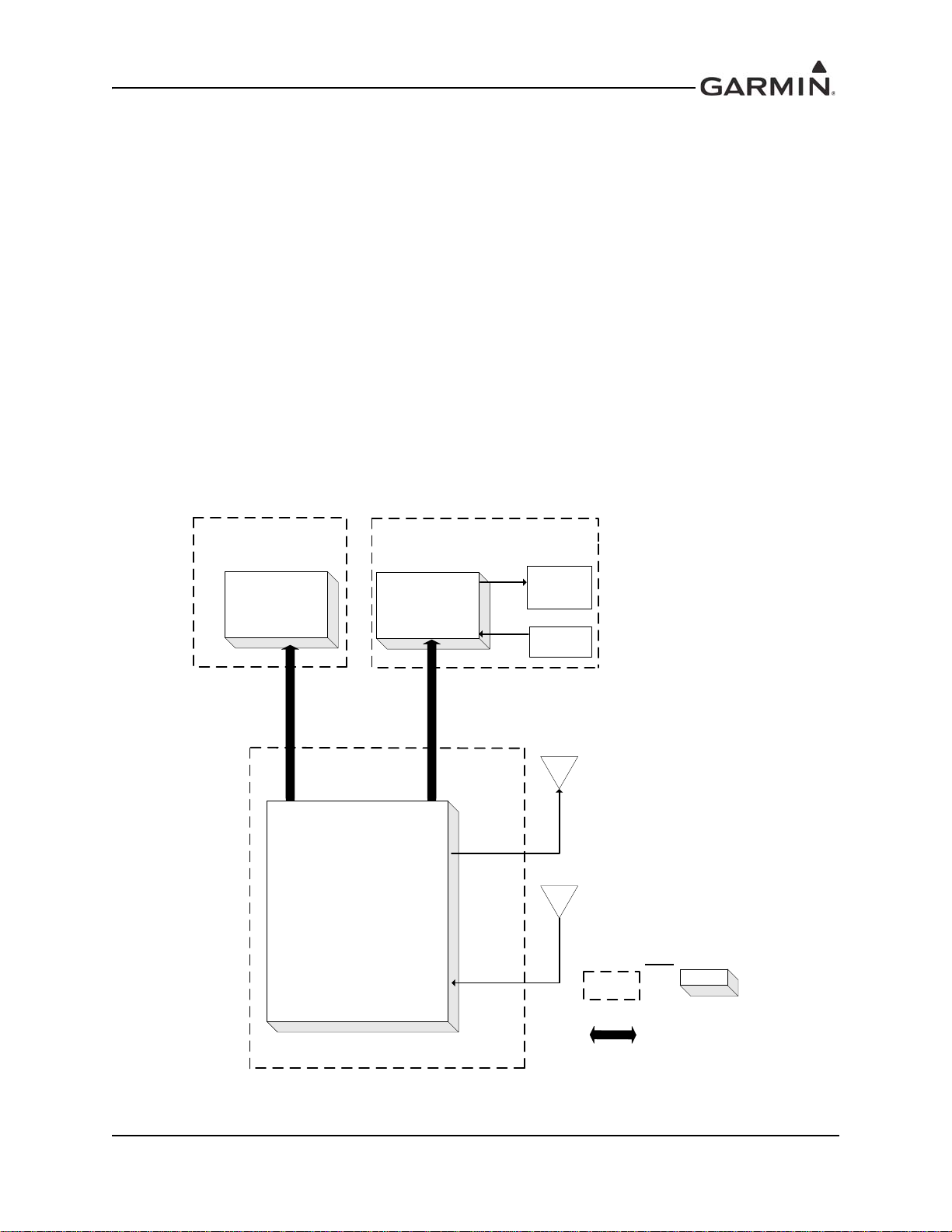
2.1 Description of Alteration
This STC upgrades the existing functionality of the Bell 206B, 206L series aircraft avionics system as
summarized below.
The GRA 55/5500 radar altimeter system features: two antenna architecture for transmitting and receiving
radio waves for altitude quantities, remote mounted LRU transceiver for quantifying Above Ground Level
(AGL) altitude information, and interface capabilities to the existing aircraft G500H Flight Deck System
(FDS) for pilot display of aircraft altitude and system degraded warnings. The GRA 55/5500 radar
altimeter may also integrate with an installed Garmin GTN 6XX/7XX for the purpose of providing the
optional 50 ft callout as part of optional HTAWS functionality.
The GRA 55/5500 LRU which is 3.99"x3.02"x11.62" mounted, is located on the supplied mounting rack
that is electrically bonded to the avionics shelf. The two approved radar altimeter antennas are optimally
located on the underside of the tailboom, separated by a minimum distance of 20" on center using
approved antenna mounts installed via STC SR09598RC, STC SR02162LA or other mounting provisions
that are compatible with the approved radar altimeter antennas. The system requires a 5 Amp minimum
circuit breaker installed on the overhead panel to supply power.
2.2 Block Diagram
Figure 2-1. GRA 55/5500 Block Diagram
190-01277-A3 System Maintenance Manual GRA 55/5500 Bell 206 STC
Rev. 1 Page 2-1
Page 13

3 GRA 55/5500 CONTROL AND OPERATION
NOTE
3.1 Control, Operating, and Testing Information
The GRA 55/5500 is a fully automated, remote-mounted LRU which requires no user controls or inputs.
The GRA 55/5500 displays the radar altitude height above ground level on compatible display systems.
Radar altitudes will be displayed ranging from ground level to 2550ft AGL.
The GRA 55/5500 has a built-in self-test (BIST/BITE) and fault logging functionality which includes
automated self-test and fault detection monitoring of the entire internal TX and RX circuitry. This feature
occurs every time the unit power is cycled and subsequently every minute during normal operation at
calculated altitudes ranging from 250ft to 2550ft AGL and during “No Computed Data” (NCD) conditions.
The GRA 55/5500 will encounter NCD conditions; at actual altitudes above 2550ft AGL, during excess
pitch or roll maneuvering, or anytime the ground reflection is poor.
3.2 Downloading and Installing the GRA 55/5500 Retrofit Installation Tool
GRA 55/5500 configuration, calibration, diagnostics, and software upgrades are performed using a
personal computer (installed with Microsoft Windows XP Service Pack 3 or later) and the GRA 55/5500
Retrofit Installation Tool, Garmin part number 006-A0451-00. The tool is available for download from the
Dealer Resource Center portion of the Garmin website (www.garmin.com). See the accompanying
“readme” file in the tool’s installation directory for the latest instructions.
A standard USB-A plug to USB-B plug commercial cable (not provided) is required to
interface between a personal computer USB-A receptacle and the GRA 55/5500 USB-B
receptacle installed in the wiring harness. This dongle cable is required to use the GRA
55/5500 Retrofit Installation Tool.
Installation
1. Once downloaded, launch the installation file from the directory in which it is stored (or use the
web browser’s download shortcuts).
2. The GRA 55/5500 Retrofit Installation Tool Setup Wizard will begin.
3. Click “Next” as prompted by the setup wizard, and adjust any settings (e.g. installation directory)
as needed.
4. The last screen of the setup wizard will show “Installation Complete.” Click the “Close” button to
close the setup wizard.
190-01277-A3 System Maintenance Manual GRA 55/5500 Bell 206 STC
Rev. 1 Page 3-1
Page 14
3.3 Using the GRA 55/5500 Retrofit Installation T ool
Once the GRA 55/5500 Retrofit Installation Tool has been installed:
1. Connect the PC to the GRA 55/5500
2. Start the GRA 55/5500 Retrofit Installation Tool from the provided “Start Menu” shortcut, or
launch the application from its program folder
3. Power-up the GRA 55/5500 by applying aircraft power
4. The connection status in the lower, right-hand corner of the GRA 55/5500 Retrofit Installation
Tool will transition from “Not Connected,” to “Connected.”
5. If the GRA 55/5500 Retrofit Installation Tool does not display “Connected” in the lower, righthand corner, check the installation and make sure the GRA 55/5500 has been powered-up and that
the USB cable is properly connected to the PC.
If the PC displays a “Found New Hardware” wizard, the GRA 55/5500 Retrofit Installation Tool was not
able to automatically install the device driver. It may be necessary to manually install the device drivers.
Copies of the drivers’ “.inf” and “.dll” files are located in the target installation directory selected during
installation. Consult the PC’s operating system documentation on manually installing drivers.
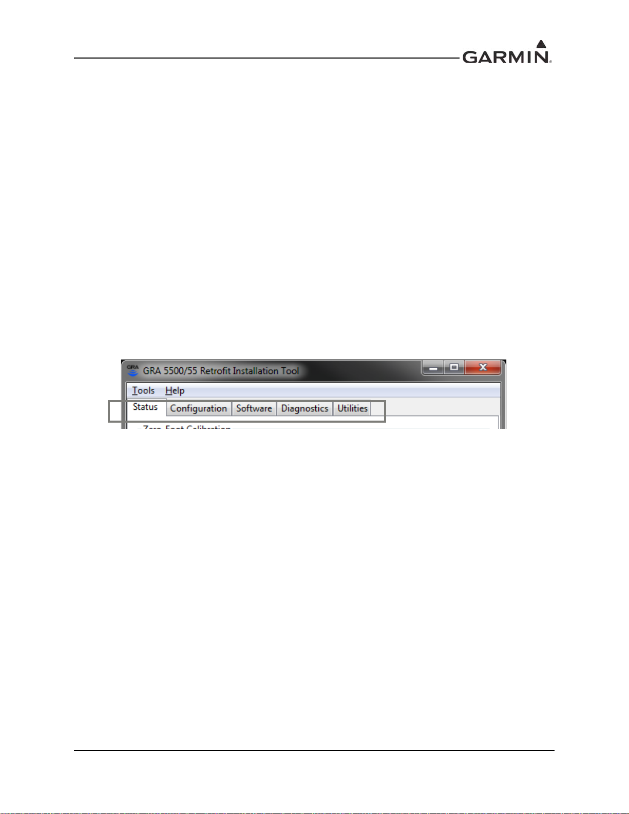
3.4 Installation Tool Pages
The Installation Tool contains five tabbed pages, all of which can be useful in troubleshooting a problem.
The pages are: Status, Configuration, Software, Diagnostics, and Utilities (See Figure 3-1).
Figure 3-1. Installation Tool Page Tabs
190-01277-A3 System Maintenance Manual GRA 55/5500 Bell 206 STC
Rev. 1 Page 3-2
Page 15

3.4.1 Status Page
The status page (Figure 3-2) is displayed by selecting the Status tab. This page provides the basic fault
status of the unit. During normal operation, the status of each fault should indicate “normal.” If the unit
indicates a fault, the fault’s entry on the list is displayed in a bold, red font. The status also updates to show
the specific failure under that fault. Table 5-1 identifies the various unit faults that can be encountered
during normal operation of the GRA 55/5500. Use Table 5-1 as a reference to determine the proper actions
to take after a fault has been identified.
Figure 3-2. Status Page
190-01277-A3 System Maintenance Manual GRA 55/5500 Bell 206 STC
Rev. 1 Page 3-3
Page 16

3.4.2 Configuration Page
The configuration page (Figure 3-3) provides an interface to change the unit’s per-airframe configuration.
The configuration tab displays the unit’s current settings. After adjusting any settings, the “Save
Configuration to Unit” button must be clicked to send the configuration values to the GRA 55/5500.
Clicking the button labeled “Restore Defaults to Unit” restores all settings to their default, factory state.
The GRA 55 does not utilize ARINC 429 Channel 2 and that section will not be selectable.
Figure 3-3. Configuration Page
190-01277-A3 System Maintenance Manual GRA 55/5500 Bell 206 STC
Rev. 1 Page 3-4
Page 17

3.4.3 Software Page
The software page (Figure 3-4) provides a list of currently installed software regions on the GRA 55/5500
as well as an interface to load new software regions to the unit.
Figure 3-4. Software Page
190-01277-A3 System Maintenance Manual GRA 55/5500 Bell 206 STC
Rev. 1 Page 3-5
Page 18

3.4.4 Diagnostics Page
The Diagnostics Page (see Figure 3-5) allows the user to download the unit’s assert log. In normal
condition, there should be no logged asserts and this page will be disabled. If an assert has been logged to
the unit, the “Download Asserts” button will be selectable. This will download the logged asserts from the
unit and display them on the Assert Log Records list. Basic information about each assert (the power-on
cycle, the total power-on time, the type of fault or assert, and the status message accompanying the assert)
is displayed.
The “Capture Raw Log to File…” button and the “Export Log to CSV…” button may be used to save the
assert log (for further diagnostic evaluation). The raw log option will be most helpful when communicating
issues to Garmin Engineering. The CSV log option will be most helpful for end-users not familiar with the
internal logging format. These two buttons will only be selectable after the assert log has been downloaded
from the unit.
Figure 3-5. Diagnostics Page
190-01277-A3 System Maintenance Manual GRA 55/5500 Bell 206 STC
Rev. 1 Page 3-6
Page 19

3.4.5 Utilities Page
The Utilities Page (see Figure 3-6) displays statistics and information about the current state of the unit.
These values are updated every two seconds. All values are labeled, and include units (where necessary).
Minimum and Maximum internal temperatures experienced by the unit during operation are also
displayed.
Figure 3-6. Utilities Page
190-01277-A3 System Maintenance Manual GRA 55/5500 Bell 206 STC
Rev. 1 Page 3-7
Page 20

3.4.6 Zero-Foot Calibration
Anytime the GRA 55/5500 is removed and reinstalled in the helicopter, a one-time zero-foot calibration
procedure must be performed on the unit in order to “zero” the altitude outputs from the unit. This
procedure removes the altitude offsets associated with antenna cables, antenna height above ground, etc.
This procedure is performed via the GRA 55/5500 Retrofit Installation Tool.
The following conditions must be met before the zero-foot calibration procedure should be attempted:
1. The entire GRA 55/5500 must be completely installed and mounted in the final configuration as
representative of normal flight conditions.
2. A visual inspection must be performed to verify antenna installation and the antenna coaxial cables
are installed and connected properly.
3. The zero-foot calibration procedure must be performed outdoors on a hard, flat surface and away
from hangars, buildings, or other metal structures that may reflect the radar signal.
4. GRA 55/5500 Retrofit Installation Tool must be connected to the GRA via USB dongle cable.
The GRA 55/5500 Retrofit Installation Tool provides an interface button to initiate the zero-foot
calibration procedure. Clicking this button will make a series of requests to the connected GRA 55/5500.
During the calibration procedure, the GRA 55/5500 Retrofit Installation Tool will report progress updates
next to the “Initiate Calibration Procedure” button. Once the calibration procedure has completed, the text
will display “Calibration Complete” and the status tab will be updated. If the fault list does not annunciate
any faults and the information displayed in the status bar area indicates “0 ft” and “Normal,” the unit has
been successfully calibrated.
190-01277-A3 System Maintenance Manual GRA 55/5500 Bell 206 STC
Rev. 1 Page 3-8
Page 21

4 INSTRUCTIONS FOR CONTINUED AIRWORTHINESS
4.1 Servicing Information
None. In the event of system failure, troubleshoot the GRA 55/5500 in accordance with Section 5 of this
document.
4.2 Periodic Maintenance
The GRA is designed to detect internal failures. A thorough self-test is executed automatically upon
application of power to the unit. Furthermore, automated built-in tests (BIT) are continuously executed
every minute within the altitude range of 250ft to 2550ft.
Operation of the GRA 55/5500 is not permitted unless the inspections described in this section have been
completed within the time intervals prescribed in Table 4-1.
4.3 Special Tools
A milliohm meter with an accuracy of +/- 0.1 milliohms ohms (or better) is required to measure the
electrical bonding between the GRA 55/5500 LRU and aircraft ground.
190-01277-A3 System Maintenance Manual GRA 55/5500 Bell 206 STC
Rev. 1 Page 4-1
Page 22

4.4 Maintenance Intervals
Table 4-1. Maintenance Intervals for GRA 55/5500
Item Description/Procedure Interval
Removal and replacement of the following items. See
Equipment Removal
and Replacement
Test – Bonding Check,
GRA 55/5500 &
MOUNT RACK
Section 6 for removal and replacement instructions.
• GRA 55/5500 Mount Rack
• GRA 55/5500 LRU
• Antenna
Perform an electrical bonding check as follows:
1. Disconnect the wire harnesses from the GRA 55/
5500 at P55001, TX, and RX connections.
2. Measure the resistance between the mounting rack
and a nearby exposed portion of metallic structure.
Verify that the resistance is less than or equal to
2.5 milliohms.
3. Measure the resistance between the GRA 55/5500
LRU and the mounting rack. Verify that the
resistance is less than or equal to 2.5 milliohms.
In the event of a bonding test failure, remove the LRU
and rack, if required, and verify that the mating surfaces
for the LRU and/or mounting rack are free of corrosion
or any other debris. Clean, inspect and re-burnish (if
required) all mating surfaces using approved methods
and solvents per Bell specification
BHT-ELEC-SPM CHP 8.
Reinstall the mounting rack and GRA LRU to the
designated location.
Re-verify the resistance between the mounting rack and
nearby exposed portion of aircraft metallic structure and
ensure that the resistance is less than or equal to
2.5 milliohms.
Re-verify the resistance between the GR A LRU the
mount rack. Ensure the resistance is less than or equal
to 2.5 milliohms.
On Condition
To be performed in
alignment with Bell
206B, 206L series
maintenance
schedule. Every 10
years or every 2000
hours, whichever
comes first.
4. Reconnect the previously disconnected wire
harnesses ensuring that the coaxial connectors are
reconnected into their respective locations.
190-01277-A3 System Maintenance Manual GRA 55/5500 Bell 206 STC
Rev. 1 Page 4-2
Page 23

Item Description/Procedure Interval
Hard Landing
Inspection
1. Complete visual examination of rotorcraft structure
(shelf) supporting GRA unit for damage to verify
integrity, including unit mounting rack and rack
fasteners. Check and re-torque mounting rack
fasteners 20 to 25 in-lbs if required. Repair GRA
unit support structure in accordance with BHT-206SRM-1 Structural Repair Manual, and BHT-ALLSPM Bell Standard Practices Manual if required.
2. Visually inspect integrity of the GRA unit for
damage. Operation of the GRA unit is verified
through unit self-test at power-up.
3. Visually inspect integrity of the GRA antennas,
antenna fasteners, and antenna sealant for
damage. If required, check and re-torque antenna
fasteners 20 to 25 in-lbs, and remove and replace
antenna sealant (MIL-A-46146).
4. Inspect all system connectors for FOD and check
for bent, broken, or recessed pins.
On Condition
190-01277-A3 System Maintenance Manual GRA 55/5500 Bell 206 STC
Rev. 1 Page 4-3
Page 24

Item Description/Procedure Interval
Visual Inspection
The GRA mount, unit and wiring harnesses should be
inspected to ensure continued integrity of the
installation in alignment with Chapter 5, under the
relevant section covering 100-Hour and Annual
Inspections of applicable Bell 206B, 206L series
Model Maintenance Manual. Perform a visual
inspection of the GRA unit, unit mount, and wiring
harnesses to verify integrity.
1. Inspect the GRA unit for sec urity of attachment,
including visual inspection of the mounting rack
and rotorcraft support structure to which the rack
is attached. Verify the fastener heads are in full
contact with unit mounting rack and re-torque 20
to 25 in-lbs if required.
2. Inspect GRA55/5500 unit, unit mounting rack, and
rotorcraft support structure for signs of corrosion
and apparent signs of damage. If corrosion is
found, treat affected areas in accordance with
Chapter 3 of BHT-ALL-SPBM Bell Helicopter
Standard Practices Manual, Revision 2, or later
approved revision. If damage to GRA unit support
structure is found, repair as required in
accordance with BHT-206-SRM-1 Structural
Repair Manual, Revision 3, or later approved
revision.
3. Inspect placards and all labels. Ensure that they
are legible and properly adhered. Damaged
placards and labels should be replaced as
necessary.
4. Inspect wire and shield terminations, condition of
wiring harness, routing, and security of its
attachment/clamping to rotorcraft structure. Check
for chaffed or damage wires and ensure overall
functionality of wire installation.
5. Inspect all system connectors for bent/broken or
recessed pins. Inspect connectors for FOD.
To be performed in
alignment with Bell
206B, 206L series
maintenance
schedule. Every 100
flight hours or every
12 months,
whichever comes
first.
190-01277-A3 System Maintenance Manual GRA 55/5500 Bell 206 STC
Rev. 1 Page 4-4
Page 25

Table 4-2. Maintenance Intervals for Antennas Replaced Under this STC
Item Description/Procedure Interval
Test – Bonding Check,
Antennas
An electrical bonding test must be performed on
antennas installed by this STC.
1. Gain access to the antenna installation.
2. Remove one each mounting screw from the
antenna if not already done. Check that the
remaining hardware is installed and properly
torqued.
3. Measure the resistance between the e xposed metal
in the empty mounting hole of the antenna and a
nearby exposed portion of conductive aircraft
structure (i.e. exposed rivet). Verify that the
resistance is less than or equal to 2.5 milliohms.
4. Reinstall the antenna mounting screw, torque as
specified. Reseal the antenna as required.
In the event of a bonding test failure, remove the failed
antenna, Clean and inspect all hardware and mating
surfaces using approved solvents and metho ds per Bell
specification BHT-ELEC-SPM CHP 8.
For antennas that are secured with nuts and bolts,
clean the fastener hole in the antenna and the
underside of the fastener head itself. Prep the area
underneath the washer on the inner mould line of the
skin in accordance with Bell Specification
BHT-ELEC-SPM CHP 8. If nutplates are used in lieu of
a nut, the technician is only required to clean the
underneath of the fastener head and the fastener hole.
To be performed in
alignment with Bell
206B, 206L series
maintenance
schedule. Every 10
years or every 2000
hours, whichever
comes first.
For antennas that use stud mounts, prep the area
underneath the washer on the inner mould line of the
skin in accordance with Bell Specification
BHT-ELEC-SPM CHP 8.
Re-install using Antenna Installation procedures in
Section 6.3. Any reworked antenna installation shall
have a resistance of less than or equal to 2.5 milliohms.
Re-seal the antenna as per methods specified in
BHT-ELEC-SPM CHP 8.
190-01277-A3 System Maintenance Manual GRA 55/5500 Bell 206 STC
Rev. 1 Page 4-5
Page 26

Item Description/Procedure Interval
Visual inspection on the antenna:
1. Clean the antenna with water and mild soap.
2. Verify there are no cracks on the antenna and
around attachment fasteners.
3. Verify that all sealing fillets around the antenna are
in good condition.
If the antenna is broken, cracked, or dented it must be
replaced.
Visual Inspection of
the antennas
In the event attachment is not secure, re-attach an tenna
and complete the Electrical Bonding Test.
In the event the antenna seal shows signs of damage,
complete the Electrical Bonding Test and re-seal the
antenna.
Visual inspection of the rotorcraft exterior skin around
installed antenna:
1. Clean the exterior of the aircraft skin within a 10
inch radius of the antenna with water and mild
soap.
2. Inspect aircraft skin around the antenna footprint to
verify there are no cracks and aircraft skin is not
deformed.
3. Verify that antenna fasteners are not loose.
If the aircraft skin is cracked, or deformed, the internal
structure must also be inspected for degradation in the
local area. Refer to approved method defined in the
Structural Repair Manual For Bell Model 206 Series
Helicopters, BHT-206-SRM- 1, Section 3 for applicable
repairs.
To be performed in
alignment with Bell
206B, 206L series
maintenance
schedule. Every 100
flight hours or every
12 months,
whichever comes
first.
Perform visual
inspection in event of
suspected lightning
strike.
190-01277-A3 System Maintenance Manual GRA 55/5500 Bell 206 STC
Rev. 1 Page 4-6
Page 27

5 TROUBLESHOOTING INFORMATION
5.1 GRA 55/5500 General Troubleshooting
This section provides troubleshooting information for the Garmin GRA 55/5500 Radar Altimeter. All
faulty units must be returned to Garmin for repair.
No internal or comprehensive unit troubleshooting is possible at the dealer service center due to the need
for specialized unit test setups and test software. However, the service center may troubleshoot a unit to
confirm a fault or the status of the unit by utilizing the following methods:
• Checking the status of monitored unit faults
• Checking the unit software versions
• Checking the unit installation configuration
• Downloading and analyzing the unit assert log
• Checking the unit statistics and internal recorded unit temperatures
The troubleshooting methods listed herein are employed using the GRA 55/5500 Retrofit Installation Tool
as described in the following sections.
Table 5-1. GRA 5500 Fault Descriptions
Fault Type Fault Name Description Cause Resolution
Configuration N/A Unit does not boot
Average frequency
of zero-foot signal
Zero-Foot Lock
Calibration
Zero-Foot Cal
is larger/smaller
than allowable
frequencies
Zero-Foot point is
not set
GRA HW Revision
ID invalid for SW
version
GRA Unit ID
invalid (Both
discrete inputs
grounded)
Hardware failure
Improper antenna
connections
Calibration not
complete
Update software to
correct version for
hardware
Check Unit ID
strapping and set
to a valid ID
Return unit to
Garmin for service
Check antenna
installation and all
cable connections
and retry
calibration. Note
there are no assert
log entries for this
fault.
Calibrate unit while
on ground. Note
there are no assert
log entries for this
fault.
190-01277-A3 System Maintenance Manual GRA 55/5500 Bell 206 STC
Rev. 1 Page 5-1
Page 28

Fault Type Fault Name Description Cause Resolution
POST (Power On
Self-Test)
PLL Register
RF Self-Test
Sensor Boot
Various [1]
After programming,
read-back of the
PLL register values
does not match
what was sent from
the CPU
The self-test signal
is not within the
acceptable
frequency range
Sensor processor
software not
successfully loaded
Numerous tests
identified in this
table are run during
Power On Self-Test
(POST). Failure of
these tests is
identified as a
POST fault during
power up and also
identified by the
fault name in the
fault log.
Internal
communication
error
Improper antenna
connections
Internal failure
Internal
communication
error
Various [1]
Cycle power to
unit. If fault
persists, return unit
to Garmin for
service.
Check antenna
installation and all
cable connections.
Download the
assert log and
send to Garmin for
diagnosis. If fault
persists, return unit
to Garmin for
service.
Cycle power to
unit. If fault
persists, return unit
to Garmin for
service.
190-01277-A3 System Maintenance Manual GRA 55/5500 Bell 206 STC
Rev. 1 Page 5-2
Page 29

Fault Type Fault Name Description Cause Resolution
Clock Generator is
read to determine
correct frequency
output.
Sensor is read to
determine correct
operation.
ADC did not
respond to
sampling
conversion
command within
20us
ADC used to
monitor internal unit
voltages fails
self-test
Clock generator
programming
failure
Memory integrity
test
Failed to validate
code sections in
memory
Sensor processor
code failed validity
check
Sensor CPU fails to
respond to Main
CPU or packet
information is not
correct from sensor
Sensor processor
reset signal
triggered by sensor
watchdog
Internal
communication
error
ADC failure
Clock generator
failure
Memory failure
Code corrupted in
flash memory
Code corrupted
during transfer
from flash to RAM
Code corrupted
during transfer
from flash to main
processor
Code corrupted
during transfer
from main to
sensor processor
Sensor processor
failure
Internal
communication
error
Sensor processor
failure
Internal
communication
error
Cycle power to
unit. If fault
persists, return unit
to Garmin for
service.
Cycle power to
unit. If fault
persists, return unit
to Garmin for
service.
Digital HW
Digital HW
Clock Generator I2C
Main Temp Sensor I2C Temperature
RF Temp Sensor I2C
ADC (Voltage Monitor)
ADC Monitor (X)
(Fault also included in
POST, Power On Self
Test Faults) [1]
Clock Generator
Register
DDR
Flash-to-RAM Code
Sensor Code CRC
Sensor Status
Sensor Watchdog
190-01277-A3 System Maintenance Manual GRA 55/5500 Bell 206 STC
Rev. 1 Page 5-3
Page 30

Fault Type Fault Name Description Cause Resolution
Check aircraft
power supply.
Cycle power to
unit.
If fault persists,
download the
assert log and
send to Garmin for
diagnosis.
Check aircraft
power supply.
Cycle power to
unit.
If fault persists,
download the
assert log and
send to Garmin for
diagnosis.
Check aircraft
power supply.
Cycle power to
unit.
If fault persists,
download the
assert log and
send to Garmin for
diagnosis.
Check aircraft
power supply.
Cycle power to
unit.
Check aircraft
power supply.
Cycle power to
unit.
If fault persists,
download the
assert log and
send to Garmin for
diagnosis.
Electrical
(+ / -) 12.5V Monitor
(Fault also included in
POST, Power On Self
Test Faults) [1]
+12.5V RF Monitor
(Fault also included in
POST, Power On Self
Test Faults) [1]
+8V RF Monitor
(Fault also included in
POST, Power On Self
Test Faults) [1]
+80V Backup Monitor
(Fault also included in
POST, Power On Self
Test Faults) [1]
-6V RF Monitor
(Fault also included in
POST, Power On Self
Test Faults) [1]
(+ / -) 12.5 V power
rail outputs
improper voltage
+12.5 V RF power
rail outputs
improper voltage
+8 V RF power rail
outputs improper
voltage
+80 V backup
power rail outputs
improper voltage
-6 V RF power rail
outputs improper
voltage
Aircraft power
input voltage out of
range
Internal power
supply failure
Aircraft power
input voltage out of
range
Internal power
supply failure
Aircraft power
input voltage out of
range
Internal power
supply failure
Aircraft power
input voltage out of
range
Aircraft power
input voltage out of
range
Internal power
supply failure
190-01277-A3 System Maintenance Manual GRA 55/5500 Bell 206 STC
Rev. 1 Page 5-4
Page 31

Fault Type Fault Name Description Cause Resolution
Check aircraft
power supply.
Cycle power to
unit.
If fault persists,
download the
assert log and
send to Garmin for
diagnosis.
Check aircraft
power supply.
Cycle power to
unit.
If fault persists,
download the
assert log and
send to Garmin for
diagnosis.
Check aircraft
power supply.
Cycle power to
unit.
If fault persists,
download the
assert log and
send to Garmin for
diagnosis.
Check aircraft
power supply.
Cycle power to
unit.
If fault persists,
download the
assert log and
send to Garmin for
diagnosis.
Check aircraft
power supply.
Cycle power to
unit.
If fault persists,
download the
assert log and
send to Garmin for
diagnosis.
+5.75V RF Monitor
(Fault also included in
POST, Power On Self
Test Faults) [1]
+5.75V Monitor
(Fault also included in
POST, Power On Self
Test Faults) [1]
Electrical
+3.3V Monitor
(Fault also included in
POST, Power On Self
Test Faults) [1]
+1.9V Monitor
(Fault also included in
POST, Power On Self
Test Faults) [1]
Electrical Current Monitor
+5.75 V RF power
rail outputs
improper voltage
+5.75 V power rail
outputs improper
voltage
+3.3 V power rail
outputs improper
voltage
+1.9 V power rail
outputs improper
voltage
Improper current on
+8 V power rail
Aircraft power
input voltage out of
range
Internal power
supply failure
Aircraft power
input voltage out of
range
Internal power
supply failure
Aircraft power
input voltage out of
range
Internal power
supply failure
Aircraft power
input voltage out of
range
Internal power
supply failure
Aircraft power
input voltage out of
range
Internal power
supply failure
190-01277-A3 System Maintenance Manual GRA 55/5500 Bell 206 STC
Rev. 1 Page 5-5
Page 32

Fault Type Fault Name Description Cause Resolution
Check aircraft
power supply.
Cycle power to
unit.
Return power to
unit. Note there are
no assert log
entries for this
fault.
Cycle power to
unit. If fault
persists, return unit
to Garmin for
service.
If fault persists,
download the
assert log and
send to Garmin for
diagnosis.
If fault persists,
download the
assert log and
send to Garmin for
diagnosis.
Check antenna
installation and all
cable connections.
If fault persists,
download the
assert log and
send to Garmin for
diagnosis.
Check antenna
installation and all
cable connections.
Download the
assert log and
send to Garmin for
diagnosis. If fault
persists, return unit
to Garmin for
service.
Suspended Power Fail
DDS
TX PLL Lock
LO PLL Lock
Radio HW
Auto RF Self-Test
Main RF Self-Test
Aircraft power lost
for greater than 220
ms
Failure to program
DDS or read back
correct register
information from
the DDS
The TX PLL is not
locked while the
unit is transmitting.
The LO PLL is not
locked while the
unit is transmitting
The self-test signal
is not within the
acceptable
frequency range
The self-test signal
is not within the
acceptable
frequency range
Internal power
supply failure
Aircraft power
failure
Internal
communication
error
Internal failure
Internal failure
Improper antenna
connections
Internal failure
Improper antenna
connections
Internal Failure
190-01277-A3 System Maintenance Manual GRA 55/5500 Bell 206 STC
Rev. 1 Page 5-6
Page 33

Fault Type Fault Name Description Cause Resolution
Installed unit
location is too hot/
Main Temp
(Fault also included in
POST, Power On Self
Test Faults) [1]
Temperature
RF Temp
(Fault also included in
POST, Power On Self
Test Faults) [1]
[1] Fault can be found in the Power on Self Test (POST) fault list and in normal operational
mode fault list. Review Table 5-1 fault tree for identification.
Main board
temperature
greater than 100° C
or less than -60° C
RF board
temperature
greater than 100° C
or less than -60° C
cold
Internal failure
Installed unit
location is too hot/
cold
Internal failure
Return unit to
qualified
temperature range
as specified in
Environmental
Qualification Form
(EQF). If fault
persists, return unit
to Garmin for
service.
Return unit to
qualified
temperature range
as specified in
Environmental
Qualification Form
(EQF). If fault
persists, return unit
to Garmin for
service.
190-01277-A3 System Maintenance Manual GRA 55/5500 Bell 206 STC
Rev. 1 Page 5-7
Page 34

6 REMOVAL AND REPLACEMENT INFORMATION
6.1 Unit Installation
6.1.1 Installation Procedure
1. Place the unit on the mounting rack, ensuring the GRA 55/5500 rear feet are aligned in the
mounting rack slots.
2. Slide the GRA 55/5500 back until the feet are fully engaged with the mounting rack.
3. Lift the lockdown collar in place on the GRA 55/5500 hook and hand turn the lockdown
mechanism knob clockwise until the GRA 55/5500 is secure and the knob cannot reasonably be
ratcheted any tighter by hand.
6.1.2 Removal Procedure
1. Pull back on the lockdown mechanism and simultaneously turn counterclockwise until free.
2. Disengage the lockdown mechanism collar from the GRA 55/5500 hook and slide the
GRA 55/5500 forward to remove from the mounting rack.
6.2 Rack Installation
The GRA 55/5500 mounting surface should be capable of providing a sufficient electrical bond to the
aircraft to minimize Electromagnetic Interference (EMI) and provide protection from High-Intensity
Radiation Fields (HIRF). Bonding resistance measured between the GRA 55/5500 mounting rack and the
airframe must measure less than 2.5 milliohms.
6.2.1 Installation Procedure
1. Clean and inspect the mounting surface of the rack mount. Ensure the bonding surface is adequate
to meet the required resistance measurement of 2.5 milliohms.
2. Place the rack on the mounting shelf assembly with lockdown knob facing forward.
3. Install and secure mount rack with 4 ea. screw (see Table A-1for rack fasteners).
Torque 20-25 in lbs.
4. Perform bond resistance measurement. Value should be less than 2.5 milliohms.
6.2.2 Removal Procedure
1. Remove GRA 55/5500 unit if not already done.
2. Remove 4 ea. screw (see Table A-1for rack fasteners).
3. Remove mounting rack.
6.3 Antenna Installation
6.3.1 Installation Procedure
1. Clean and inspect the antenna mount. Remove debris and excess sealant if replacing existing
antenna.
2. Apply the conductive gasket on the underside of the antenna using the fastener holes as guides.
3. Use MS24693-C272 stainless steel countersunk head machine screws (No. 10, supplied) to secure
antennas. Verify that directional arrow on the antenna is pointed towards the front of the helicopter.
4. Torque antenna fasteners in a star pattern to 20-25 in lbs. Torque should be applied evenly across
all fasteners to avoid deformation of the mounting area.
5. Ensure that the antenna base and antenna mount are in continuous contact with the gasket.
190-01277-A3 System Maintenance Manual GRA 55/5500 Bell 206 STC
Rev. 1 Page 6-1
Page 35

6. Seal the antenna and gasket with an approved sealant compound (MIL-A-46146) along the edge of
UNIT HOOK
ENGAGEMENT
FEET
2 PLACES
FEET ENGAGEMENT
LOCATION
2 PLACES
LOCKDOWN MECHANISM COLLAR
LOCKDOWN MECHANISM KNOB
SECTION VIEW SHOWING
UNIT FEET ENGAGED INTO
MOUNTING RACK
2 PLACES
the antenna where it meets the antenna mount.
6.3.2 Removal Procedure
1. Remove the sealant compound (MIL-A-46146) along the edge of the antenna where it meets the
antenna mount using a non-metallic scraper.
2. Remove the hardware retaining the antenna in place.
3. Lower the antenna enough to disconnect the coaxial connector, and disconnect.
4. Remove the antenna and conductive gasket from the airframe.
190-01277-A3 System Maintenance Manual GRA 55/5500 Bell 206 STC
Rev. 1 Page 6-2
Figure 6-1. GRA 55/5500 Installation
Page 36

COMPARTMENT, BELL 206 L SERIES, OR 206-031-309-115 WEB
INSTALLATION, STA 130.00 TO 192.84, BELL 206B
REF. EXISTING 206-031-339-027 PANEL ASSEMBLY, BAGGAGE
MOUNTING SHELF ASSEMBLY
0.20 4 PLCS
REF. ADDED OR EXISTING
8 PLCS
0.179-100
0.098 THROUGH
TBS
50.22
TBS
31.80
TBS
71.44
S67-2002 RADAR ALTIMETER ANTENNA
INCLUDED WITH 013-00378-00 ANTENNA KIT
EXISTING ANTENNA MOUNTS
S67-200222 CONDUCTIVE GASKET, 0.020 INCH THICK
INCLUDED IN ANTENNA KIT
GARMIN P/N 013-00378-00 (2X)
MS24693-C272 SCREW, MACHINE COUNTERSUNK .1900-32UNF 2A
INCLUDED WITH 013-00378-00 ANTENNA KIT. TYP. 4 PLCS
Figure 6-2. Rack Installation
Figure 6-3. GRA 55/5500 Antenna Installation
190-01277-A3 System Maintenance Manual GRA 55/5500 Bell 206 STC
Rev. 1 Page 6-3
Page 37

7 RETURN TO SERVICE PROCEDURE
7.1 Return to Service
1. Perform Zero-Foot Calibration in accordance with Section 3.4.6.
2. Verify no faults exist in the Assert Log page prior to disconnecting Retrofit Installation Tool.
3. Verify that radar altitude is displayed correctly on the installed display with the GRA 55/5500 and
display powered on. If radar altitude is not displayed, verify correct configuration.
7.2 Maintenance Records
After conducting required return-to-service procedures in accordance with this document, the aircraft may
be returned to service. Record the following information in the aircraft maintenance logs:
1. Software versions loaded as part of any maintenance action.
2. Record part and serial numbers of any LRU that was replaced.
3. Any other applicable information related to the maintenance work performed on the aircraft.
190-01277-A3 System Maintenance Manual GRA 55/5500 Bell 206 STC
Rev. 1 Page 7-1
Page 38

8 LIMITATIONS AND ADDITIONAL REQUIREMENTS
8.1 Diagrams
Aircraft specific LRU locations and wire routing diagram are contained in Appendix A of this document.
Completed forms are to be retained with the aircraft permanent records.
Point-to-point wiring diagrams for the GRA 55/5500, and interfaced equipment shall be included with the
aircraft permanent records.
GRA 55/5500 component locations are described in Appendix A of this document.
8.2 Special Inspection Requirements
Visual inspection of antenna(s) must be performed if aircraft is suspected or was actually struck by
lightning. The scope of inspection shall extend to the GRA 55/5500 antennas and rotorcraft structure
supporting antenna installation to verify there is no damage. See Table 4-2 for inspection criteria.
Execute the system checkout procedure for the GRA 55/5500 system to ensure the system is operating
correctly.
8.3 Application of Protective Treatments
None. N/A.
8.4 Data Relative to Structural Fasteners
See Table A-1 and Figure A-3 for LRU fastener information. See Figure 6-3 for Antenna fastener
information.
8.5 Additional Instructions
None. N/A.
8.6 Overhaul Period
The system does not require overhaul at a specific time period. Power on self-test and continuous BIT will
monitor the health of the GRA system. If the LRU indicates an internal failure, the unit may be removed
and replaced (See Section 6 for Removal and Installation instructions). See Section 5 for troubleshooting
information.
8.7 ICA Revision and Distribution
To revise this ICA, Garmin will follow the Garmin ODA Procedures Manual SOP-0055/ACP-0016 for
Instructions for Continued Airworthiness. The latest revision of this ICA document is available on the
Garmin website (www.flyGarmin.com
select ‘Manuals’. You may also contact Garmin General Aviation Product Support at 866-739-5687 (US
toll free) 913-397-8200 or avionics@garmin.com
be sent to Garmin dealers if a revision is determined to be significant.
). To Access Aviation Manuals, select the ‘Support’ tab and then
. A Garmin Service Bulletin describing ICA revision will
8.8 Assistance
Flight Standards Inspectors or the certificate holder’s PMI have the required resources to respond to
questions regarding this ICA. In addition, the customer may contact Garmin with questions regarding this
equipment and its installation. Garmin Customer Support may be contacted during normal business hours
via telephone 913-397-8200 or from the Garmin web site at www.flyGarmin.com
.
190-01277-A3 System Maintenance Manual GRA 55/5500 Bell 206 STC
Rev. 1 Page 8-1
Page 39

8.9 Implementation and Record Keeping
Modification of an aircraft by this Supplemental Type Certificate obligates the aircraft operator to include
the maintenance information provided by this document in the operator’s aircraft maintenance manual and/
or the operator’s rotorcraft scheduled maintenance program.
190-01277-A3 System Maintenance Manual GRA 55/5500 Bell 206 STC
Rev. 1 Page 8-2
Page 40

Page 41

APPENDIX A AIRCRAFT SPECIFIC INFORMATION
FS 0.00
FS130.00
FS
142.33
WL 51.67
TBS 50.22
TBS 71.44
FS136.45
WL 0.00
GRA RADAR ALTIMETER INSTALLATION
REF. EXISTING AVIONICS SHELF
CIRCUIT BREAKER INSTALLATION
REF. EXISTING ANTENNA MOUNTS
REF. GARMIN
GDU 620 DISPLAY
REF. GARMIN
GTN NAVIGATOR
FS
0.00
FS155.00
FS
161.45
FS
167.33
WL 0.00
WL51.67
TBS 71.44
TBS 50.22
CIRCUIT BREAKER INSTALLATION
GRA RADAR ALTIMETER INSTALLATION
REF. EXISTING AVIONICS SHELF
REF. EXISTING ANTENNA MOUNTS
Figure A-1 and Figure A-2 depicts the typical location for the GRA55/5500 component locations.
Figure A-1. GRA STC Equipment Fuselage Station Location for Bell 206B
Figure A-2. GRA STC Equipment Fuselage Station Location for Bell 206L Series
190-01277-A3 System Maintenance Manual GRA 55/5500 Bell 206 STC
Rev. 1 Page A-1
Page 42

Figure A-3 depicts a typical installation of the GRA55/5500 unit and rack installation as performed in the
COMPARTMENT, BELL 206 L SERIES, OR 206-031-309-115 WEB
INSTALLATION, STA 130.00 TO 192.84, BELL 206B
REF. EXISTING 206-031-339-027 PANEL ASSEMBLY, BAGGAGE
MOUNTING SHELF ASSEMBLY
0.20 4 PLCS
REF. ADDED OR EXISTING
8 PLCS
0.179-100
0.098 THROUGH
Bell 206B and Bell 206L Series and reference notations to the bill of materials. Table A-1 provides the bill
of materials in reference to Figure A-3.
Figure A-3. GRA 55/5500 Unit and Rack Installation in the Bell 206B, 206L Series
Table A-1. Bill of Materials
Item No. Part Number Source Description QTY
1
011-02537-05
011-02537-00 GRA 5500 Radar Altimeter Unit
Garmin
2 015-2573-01 Garmin Connector Kit, GRA Radar Altimeter 1
3 015-2567-00 Garmin Rack, Mounting, GRA Radar Altimeter 1
Best
Source
Best
Source
Best
Source
4 AN525-10R7
5 MS21047-3
6 MS20470AD3-3
GRA 55 Radar Altimeter Unit
Screw, Washer Head, 0.1900-32 UNF-3A, 7/16"
Long
Nut, Self-Locking, Plate, Two-Lug, Low-Height,
Steel
Rivet, Solid, Countersunk 100 Deg, Precision
Head
(1)
4
4
8
190-01277-A3 System Maintenance Manual GRA 55/5500 Bell 206 STC
Rev. 1 Page A-2
Page 43

Figure A-4 depicts the overhead panel location in the Bell 206B, 206L Series.
DETAIL B
CIRCUIT BREAKER LABEL
VIEW A OVERHEAD CONSOLE
CIRCUIT BREAKER FOR GRA RADAR ALTIMETER
REF. LABELS FOR ADDED CIRCUIT BREAKER
B
REF. EXISTING ROTORCRAFT CIRCUIT BREAKER PANEL
AA
REF. EXISTING ROTORCRAFT OVERHEAD CONSOLE
breaker console. Equipment circuit breaker placards are labeled as follows:
LRU Power Input Label
GRA Rotorcraft Power on Connector P55001 Rad Alt
The GRA 55/5500 circuit breaker is located on the Bell 206B and Bell 206L Series overhead circuit
Figure A-4. Overhead Circuit Breaker Panel in Bell 206B, 206L Series
Table A-2. Circuit Breaker Placard
190-01277-A3 System Maintenance Manual GRA 55/5500 Bell 206 STC
Rev. 1 Page A-3
Page 44

Figure A-5 depicts the typical wire harness installation for the GRA 55/5500 system, to include the coaxial
WL0.00
FS 0.00
FS142.33
FS130.00
TBS 50.22
TBS 71.44
TBS 31.8
REF. RADAR ALTIMETER ANTENNAS
REF. GRA 55/5500 WIRING HARNESS
REF. COAXIAL CABLE
REF. CIRCUIT BREAKER
cable installation for the antennas. Due to aircraft configurations, minor deviations may exist to the
depicted routing. For additional details refer to the GRA 55/5500 installation manual.
Figure A-5. GRA 55/5500 Wire Routing in the Bell 206B, 206L Series
190-01277-A3 System Maintenance Manual GRA 55/5500 Bell 206 STC
Rev. 1 Page A-4
Page 45

A.1 Weight and Balance
FS
155.00
FS 130.00
6.20
BL 0.00
6.98
BELL 206B
BELL 206L
The location of equipment as well as the weight and moment arm for the installed item is depicted in
Figure A-6.
Figure A-6. GRA 55/5500 Unit Location and Moment Arm in Bell 206B, 206L Series
Table A-3. Weight and Balance Details
Item Description Part Number
GRA 55 Radar Altimeter
1
(Bell 206B)
GRA 5500 Radar Altimeter
2
(Bell 206B)
GRA 55 Radar Altimeter
3
(Bell 206L Series)
GRA 5500 Radar Altimeter
4
(Bell 206L Series)
011-02537-05 3.5 [1]
011-02537-00 3.5 [1]
011-02537-05 3.5 [1]
011-02537-00 3.5 [1]
Weight
(LB)
[1] Weight specified includes the unit, install rack, and backplate assembly with connectors.
Longitudinal Lateral
ARM (IN) Moment ARM (IN) Moment
136.20 476.70 -6.98 -24.43
161.20 564.20 -6.98 -24.43
190-01277-A3 System Maintenance Manual GRA 55/5500 Bell 206 STC
Rev. 1 Page A-5
Page 46

Figure A-7 depicts the location of the LRUs and antennas for the GRA 55/5500 throughout the aircraft
FS 0.00
FS 130.00
FS
142.33
WL 51.67
TBS 50.22
TBS 71.44
FS 136.45
WL 0.00
GRA RADAR ALTIMETER INSTALLATION
REF. EXISTING AVIONICS SHELF
CIRCUIT BREAKER INSTALLATION
REF. EXISTING ANTENNA MOUNTS
REF. GARMIN
GDU 620 DISPLAY
REF. GARMIN
GTN NAVIGATOR
structure for the Bell 206B rotorcraft. All harnesses fabricated as part of this STC follow existing wire
bundles as depicted in Figure A-5.
Figure A-7. Bell 206B LRU and Antenna Locations
190-01277-A3 System Maintenance Manual GRA 55/5500 Bell 206 STC
Rev. 1 Page A-6
Page 47

Figure A-8 depicts the location of the LRUs and antennas for the GRA 55/5500 throughout the aircraft
FS
0.00
FS 155.00
FS
161.45
FS
167.33
WL 0.00
WL 51.67
TBS 71.44
TBS 50.22
CIRCUIT BREAKER INSTALLATION
GRA RADAR ALTIMETER INSTALLATION
REF. EXISTING AVIONICS SHELF
REF. EXISTING ANTENNA MOUNTS
structure for the Bell 206L Series rotorcraft. All harnesses fabricated as part of this STC follow existing
wire bundles as depicted in Figure A-5.
Figure A-8. Bell 206L Series LRU and Antenna Locations
190-01277-A3 System Maintenance Manual GRA 55/5500 Bell 206 STC
Rev. 1 Page A-7
Page 48

 Loading...