

Garmin GRA 10 Installation manual
GRA™ 10 Installation and Conguration Instructions
Use the Garmin® GRA 10 adapter to adapt analog information provided by a rudder-angle
sensor on your boat to your NMEA 2000® network. Your GRA 10 allows you to observe
rudder-angle information on compatible Garmin display devices connected to your NMEA 2000
network. For a list of compatible Garmin chartplotters and devices, visit www.garmin.com.
Compare the contents of this package with the packing list on the box. If any pieces are
missing, contact your Garmin dealer immediately.
Product Registration
Help us better support you by completing our online registration today. Go to http://my.garmin
.com. Keep the original sales receipt, or a photocopy, in a safe place.
Contact Garmin
Contact Garmin Product Support if you have any questions while using your GRA 10. In the
USA, go to www.garmin.com/support, or contact Garmin USA by phone at (913) 397.8200 or
(800) 800.1020.
In the UK, contact Garmin (Europe) Ltd. by phone at 0808 2380000.
In Europe, go to www.garmin.com/support and click Contact Support for in-country support
information, or contact Garmin (Europe) Ltd. by phone at +44 (0) 870.8501241.
See the Important Safety and Product Information guide in the compatible Garmin display device box for
product warnings and other important information.
CAUTION: Always wear safety goggles, ear protection, and a dust mask when drilling, cutting, or
sanding.
NOTICE: When drilling or cutting, always check the opposite side of the drilling or cutting
surface.
Needed Tools and Supplies
Heat-shrink tubing and a heat gun
•
Cable ties
•
Additional NMEA 2000 cabling and connectors (optional)
•
July 2009 190-01081-03 Rev. A Printed in Taiwan

Determining an Installation Location
When you are selecting a location to install the GRA 10 adapter, consider the following:
During installation, you connect the GRA 10 adapter to the analog gauge (or directly to the
•
engine-tilt sensor), and to the NMEA 2000 network. Therefore:
Choose a location that is within 173 in. (4.4 m) of the analog gauge (or the engine-tilt
◦
sensor) to avoid splicing bare wires.
Choose a location between the NMEA 2000 backbone and the analog gauge (or the
◦
engine-tilt sensor).
◦
If you cannot connect the adapter directly to the NMEA 2000 network, add a drop cable.
See page 3 for more information.
The adapter is IEC 60529 IPX7 waterproof, and can be submerged up to 30 minutes at
•
1 meter. Do not install the adapter in a location where it will be submerged regularly, though
the location can be subject to wash-down.
You can use cable ties (not included) to secure the adapter to an existing structure on your
•
boat.
You can use mounted-head cable ties (not included) and screws (not included) to secure the
•
adapter to a bulkhead or other suitable surface on your boat.
Install the adapter at least 2 in. (5 cm) from a magnetic compass to prevent electromagnetic
•
interference, which can cause inaccurate compass readings.
Wiring the GRA 10 Adapter
Connect the GRA 10 adapter either to an analog gauge or to the sensor directly using the bare
wires on the wiring harness.
Wiring the GRA 10 Adapter to an Analog Gauge
If your boat has an analog gauge representing the rudder angle, you can wire the GRA 10
adapter directly to the gauge. Consult the owner’s manual provided by your boat or sensor
manufacturer to determine the ground, sensor, and power (ignition) connections on the gauge.
Typically, the power (ignition) connector is labeled with a “+”, a “+12V”, an “I”, or an “IGN”
marking. The ground connector is typically labeled with a “-”, a “ ”, or a “G” marking, and
the sensor connector is typically labeled with an “S” or a “G” marking. Do not remove any
wires from the back of the gauge, and wire the GRA 10 adapter to the gauge according to the
following table.
Wiring the GRA 10 Adapter Directly to a Rudder-Angle Sensor
If your boat does not have an analog gauge representing the rudder angle, or if you choose not
to wire the adapter to an analog gauge, you can wire the adapter directly to the sensor. Consult
the owner’s manual provided by your boat or sensor manufacturer to determine the type of
sensor (resistive or generic voltage) in use, and the sending and ground terminals on the sensor.
Typically, the sending terminal is labeled with an “S” marking for sensor or a “G” marking for
gauge, and the ground terminal is typically labeled with a negative sign (-). Wire the GRA 10
adapter to the sensor according to the following table.
GRA10InstallationandCongurationInstructions
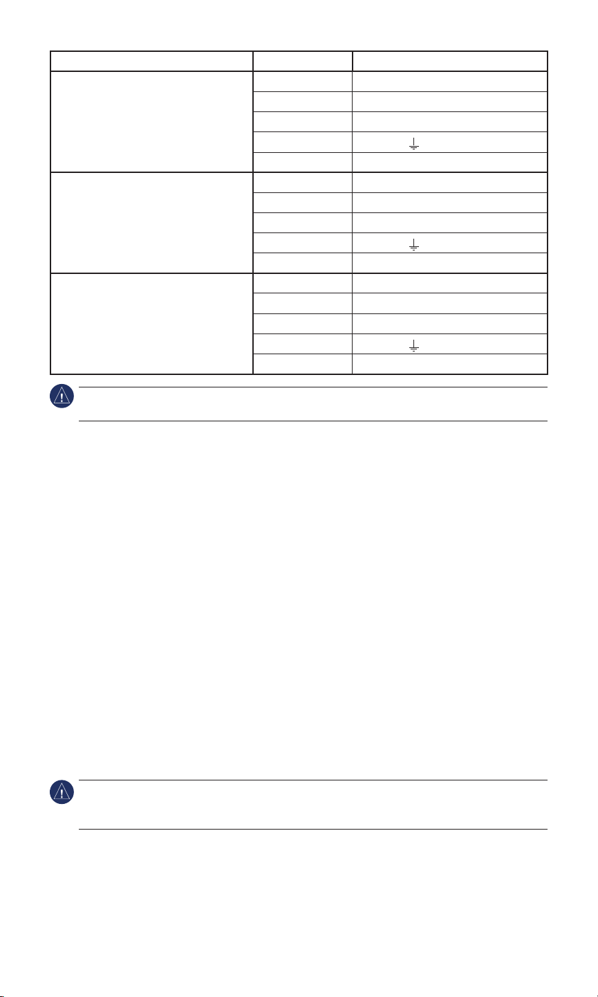
Connection Type Wire Color Gauge or Sensor Terminal
Analog Gauge Blue Sensor (S, G)
White Gauge power (+, +12V, I, IGN)
Yellow Unused
Black Ground (-, , G)
Red Unused
Resistive Sensor Blue Sensor (S, G)
White Unused
Yellow Unused
Black Ground (-, , G)
Red Unused
Generic Voltage (0–5 Vdc) Sensor Blue Unused
White Unused
Yellow Sensor (S, G)
Black Ground (-, , G)
Red 5 V power
NOTICE: After connecting the adapter to the gauge or sensor, cover any exposed wires with heat-
shrink tubing.
Connecting the GRA 10 to a NMEA 2000 Network
After you have connected the GRA 10 adapter to the analog gauge or to a sensor, connect it
to the existing NMEA 2000 network on your boat. If you do not have a NMEA 2000 network
on your boat, you must build one. For more information on NMEA 2000 and to purchase
additional connectors and cables, go to www.garmin.com.
To connect the GRA 10 adapter to your existing NMEA 2000 network:
1. Determine where to connect the GRA 10 adapter to your existing NMEA 2000 backbone.
2. Disconnect one side of a NMEA 2000 T-connector from the backbone. To extend the
NMEA 2000 backbone, connect a NMEA 2000 backbone extension cable to the side of the
disconnected T-connector.
3. Add the included T-connector for the GRA 10 adapter to the NMEA 2000 backbone by
connecting it to the side of the disconnected T-connector.
4. Connect the NMEA 2000 connector on the GRA 10 adapter to the T-connector added in
step 3.
5. (Optional) If the GRA 10 adapter cannot connect directly to the NMEA 2000 backbone, route
a NMEA 2000 drop cable (not included) to the bottom of the T-connector added in step 3.
Use a drop cable with a length up to 20 ft. (6 m). Connect the drop cable to the T-connector
and to the NMEA 2000 connector on the adapter.
NOTICE: If you have an existing NMEA 2000 network on your boat, it should already be
connected to power. Do not connect an additional NMEA 2000 power cable to an existing NMEA
2000 network, because only one power source should be connected to a NMEA 2000 network.
GRA10InstallationandCongurationInstructions
 Loading...