

Garmin GPSMAP 1022 Installation manual
GPSMAP® 10X2/12X2 SERIES
INSTALLATION
INSTRUCTIONS
Important Safety Information
WARNING
Failure to follow these warnings, cautions, and notices could
result in personal injury, damage to the vessel or device, or poor
product performance.
See the Important Safety and Product Information guide in the
product box for product warnings and other important
information.
When connecting the power cable, do not remove the in-line
fuse holder. To prevent the possibility of injury or product
damage caused by fire or overheating, the appropriate fuse
must be in place as indicated in the product specifications. In
addition, connecting the power cable without the appropriate
fuse in place voids the product warranty.
CAUTION
Always wear safety goggles, ear protection, and a dust mask
when drilling, cutting, or sanding.
To avoid possible personal injury or damage to the device and
vessel, disconnect the vessel's power supply before beginning
to install the device.
To avoid possible personal injury or damage to the device or
vessel, before applying power to the device, make sure that it
has been properly grounded, following the instructions in the
guide.
NOTICE
For the best possible performance, the device must be installed
according to these instructions.
When drilling or cutting, always check what is on the opposite
side of the surface to avoid damaging the vessel.
Read all installation instructions before proceeding with the
installation. If you experience difficulty during the installation,
contact Garmin® Product Support.
Contacting Garmin Support
• Go to support.garmin.com for help and information, such as
product manuals, frequently asked questions, videos, and
customer support.
• In the USA, call 913-397-8200 or 1-800-800-1020.
• In the UK, call 0808 238 0000.
• In Europe, call +44 (0) 870 850 1241.
Software Update
You may need to update the chartplotter software after
installation. For the instructions on how to update the software,
see the owner's manual at www.garmin.com/manuals
/GPSMAP10x2-12x2.
Tools Needed
• Drill
◦ Bail mount: drill bits appropriate for the surface and
hardware
◦ Flush mount: 14 mm (9/16 in.), 6 mm (1/4 in.) and 3.6 mm
(9/64 in.) (with nut plate), or 3.2 mm (1/8 in.) drill bit (with no
nut plate)
• #2 Phillips screwdriver
• Jigsaw or rotary tool
• File and sandpaper
• Marine sealant (recommended)
Mounting Considerations
NOTICE
This device should be mounted in a location that is not exposed
to extreme temperatures or conditions. The temperature range
for this device is listed in the product specifications. Extended
exposure to temperatures exceeding the specified temperature
range, in storage or operating conditions, may cause device
failure. Extreme-temperature-induced damage and related
consequences are not covered by the warranty.
When selecting a mounting location, you should observe these
considerations.
• The location should provide optimal viewing as you operate
your boat.
• The location should allow for easy access to all device
interfaces, such as the keypad, touchscreen, and card
reader, if applicable.
• The location must be strong enough to support the weight of
the device and protect it from excessive vibration or shock.
• To avoid interference with a magnetic compass, the device
should not be installed closer to a compass than the
compass-safe distance value listed in the product
specifications.
• The location must allow room for the routing and connection
of all cables.
• The location must not be a flat, horizontal surface. The
location should be in a vertical angle.
The location and viewing angle should be tested before you
install the device. High viewing angles from above and below
the display may result in a poor image.
Bail Mounting the Device
NOTICE
If you are mounting the bracket on fiberglass with screws, it is
recommended to use a countersink bit to drill a clearance
counterbore through only the top gel-coat layer. This will help to
avoid cracking in the gel-coat layer when the screws are
tightened.
You can use a bail mount bracket (not included) to bail mount
the device on a flat surface.
Using the bail-mount bracket as a template, mark the pilot
1
holes.
GUID-BF1B0D74-52BF-4F5B-938B-9A7556F36E8C v3October 2020
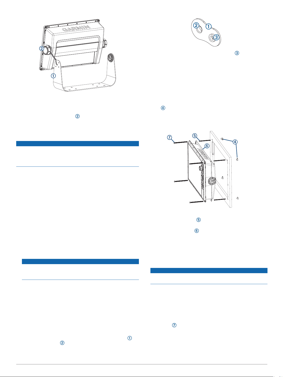
Drill the pilot holes.
2
Using appropriate mounting screws (not included), secure the
3
bail-mount bracket to the mounting surface.
Install the bail-mount knobs on the sides of the device.
4
Place the device in the bail-mount bracket and tighten the
5
bail-mount knobs.
Flush Mounting the Device
NOTICE
Be careful when cutting the hole to flush mount the device.
There is only a small amount of clearance between the case and
the mounting holes, and cutting the hole too large could
compromise the stability of the device after it is mounted.
The included template and hardware can be used to flush mount
the device in your dashboard.
Trim the template, and make sure it fits in the location where
1
you want to mount the device.
Secure the template to the mounting location.
2
Using a 14 mm (9/16 in.) drill bit, drill one or more of the holes
3
inside the corners of the solid line on the template to prepare
the mounting surface for cutting.
Using a jigsaw or a rotary tool, cut the mounting surface
4
along the inside line on the template.
Place the device in the cutout to test the fit.
5
If necessary, use a file and sandpaper to refine the size of
6
the cutout.
Use a pry tool, such as a flat piece of plastic or a screwdriver,
7
to carefully pry up the corners of the trim caps, slide the pry
tool to the center, and remove the trim caps.
NOTICE
Use a plastic pry tool when possible. Using a metal pry tool
such as a screwdriver can damage the trim caps and the
device.
After the device fits correctly in the cutout, ensure the
8
mounting holes on the device line up with the larger 6 mm
(1/4 in.) holes on the template.
If the mounting holes on the device do not line up, mark the
9
new hole locations.
Select an option:
10
• If you are using a nut plate, drill a 6 mm (1/4 in.) hole in the
larger hole location.
• If you are not using a nut plate, drill 3.2 mm (1/8 in.) holes
in the larger hole locations.
Starting in one corner of the template, place a nut plate
11
over the larger hole drilled in the previous step.
If you are using a nut plate, the smaller hole
plate should line up with the smaller hole on the template.
If the smaller hole on the nut plate does not line up with the
12
smaller hole on the template, mark the new hole location.
If you are using a nut plate, drill a 3.6 mm (9/64 in.) hole in the
13
smaller hole location.
Repeat to verify placement of the remaining nut plates and
14
holes on the template.
Remove the template from the mounting surface.
15
Starting in one corner of the mounting location, place a nut
16
plate on the back of the mounting surface, lining up the
large and small holes.
The raised portion of the nut plate should fit into the larger
hole.
Secure the nut plates to the mounting surface by fastening
17
the included M3 screws through the smaller 3.6 mm
(9/64 in.) holes.
Install the foam gasket on the back of the device.
18
The pieces of the foam gasket have adhesive on the back.
Make sure you remove the protective liner before installing
them on the device.
If you will not have access to the back of the device after you
19
mount it, connect all necessary cables to the device before
placing it into the cutout.
NOTICE
To prevent corrosion of the metal contacts, cover unused
connectors with the attached weather caps.
Apply marine sealant between the mounting surface and the
20
device to properly seal and prevent leakage behind the
dashboard.
If you will have access to the back of the device, apply
21
marine sealant around the cutout.
Place the device into the cutout.
22
Secure the device to the mounting surface using the included
23
M4 screws .
Wipe away all excess marine sealant.
24
Install the trim caps by snapping them in place around the
25
edges of the device.
on the nut
2
 Loading...