

Page 1

G3X
Installation Manual
190-01115-01 August, 2009 Revision A
Page 2

© Copyright 2009
Garmin Ltd. or its subsidiaries
All Rights Reserved
Except as expressly provided herein, no part of this manual may be reproduced, copied, transmitted,
disseminated, downloaded or stored in any storage medium, for any purpose without the express prior
written consent of Garmin. Garmin hereby grants permission to download a single copy of this manual
and of any revision to this manual onto a hard drive or other electronic storage medium to be viewed and
to print one copy of this manual or of any revision hereto, provided that such electronic or printed copy of
this manual or revision must contain the complete text of this copyright notice and provided further that
any unauthorized commercial distribution of this manual or any revision hereto is strictly prohibited.
Garmin International, Inc.
1200 E. 151
st
Street
Olathe, KS 66062 USA
Telephone: 913-397-8200
Aviation Dealer Technical Support Line (Toll Free): (888) 606-5482
www.garmin.com
Garmin (Europe) Ltd
Liberty House
Bulls Copse Road
Hounsdown Business Park
Southampton, SO40 9RB, UK
Telephone: +44 (0) 8708501241
RECORD OF REVISIONS
Revision
Revision
Date
A 08/26/09 Initial Release
Description
Page A G3X Installation Manual
Revision A 190-01115-01
Page 3
WARNING
This product, its packaging, and its components contain chemicals known to the State of
California to cause cancer, birth defects, or reproductive harm. This Notice is being
provided in accordance with California's Proposition 65. If you have any questions or
would like additional information, please refer to our web site at
www.garmin.com/prop65
.
NOTE
The Garmin G3X system includes products like the GDU 37X and the GSU 73 that are
not TSO-certified products and have received no FAA approval or endorsement.
Consequently the G3X system is not suitable for installation in type-certificated aircraft.
NOTE
Unless otherwise noted all installation guidance, requirements, and instructions apply to
one-display, two-display, and three-display G3X systems.
NOTE
References to the GDU 37X throughout this manual apply equally to the GDU 370 and
GDU 375 except where specifically noted.
INFORMATION SUBJECT TO EXPORT CONTROL LAWS
This document may contain information which is subject to the Export Administration
Regulations (“EAR”) issued by the United States Department of Commerce (15 CFR,
Chapter VII Subchapter C) and which may not be exported, released or disclosed to
foreign nationals inside or outside the United States without first obtaining an export
license. The preceding statement is required to be included on any and all reproductions
in whole or in part of this manual.
DOCUMENT PAGINATION
Section Page Range
Table of Contents i – xii
Section 1 1-1 – 1-8
Section 2 2-1 – 2-6
Section 3 3-1 – 3-6
Section 4 4-1 – 4-8
Section 5 5-1 – 5-4
Section 6 6-1 – 6-28
Section 7 7-1 – 7-14
Section 8 8-1 – 8-26
Section 9 9-1 – 9-12
Section 10 10-1 – 10-2
Appendix A A-1 – A-16
Appendix B B-1 – B-28
Appendix C C-1 – C-22
Appendix D D-1 – D4
Appendix E E-1 – E4
G3X Installation Manual Page i
190-01115-01 Revision A
Page 4

TABLE OF CONTENTS
PARAGRAPH PAGE
1 G3X Installation Overview ..............................................................................................................1-1
1.1 Unpacking Unit................................................................................................................................1-1
1.2 Introduction......................................................................................................................................1-1
1.3 System Overview.............................................................................................................................1-2
1.4 General G3X LRU Specifications....................................................................................................1-3
1.5 Installation Requirements.................................................................................................................1-5
1.6 Mounting..........................................................................................................................................1-5
1.7 Wiring/Cabling Considerations........................................................................................................1-5
2 GDU 37X.........................................................................................................................................2-1
2.1 Equipment Description.....................................................................................................................2-1
2.2 Electrical Specifications...................................................................................................................2-2
2.3 Environmental Specifications ..........................................................................................................2-3
2.4 Installation Requirements.................................................................................................................2-4
2.5 Installation Considerations...............................................................................................................2-5
2.6 Mounting Requirements...................................................................................................................2-5
2.7 Unit Installation................................................................................................................................2-5
2.8 Maintenance.....................................................................................................................................2-5
2.9 Panel Cutout Template.....................................................................................................................2-6
3 GMU 44 ...........................................................................................................................................3-1
3.1 Equipment Description.....................................................................................................................3-1
3.2 Electrical Specifications...................................................................................................................3-1
3.3 Environmental Specifications ..........................................................................................................3-2
3.4 GMU 44 TSO/ETSO Compliance....................................................................................................3-2
3.5 Installation Requirements.................................................................................................................3-3
3.6 Installation Considerations...............................................................................................................3-3
3.7 GSU 73/GMU 44 Interconnect Harness Fabrication Instructions....................................................3-5
3.8 Mounting Instructions......................................................................................................................3-6
3.9 Maintenance.....................................................................................................................................3-6
4 GSU 73.............................................................................................................................................4-1
4.1 Equipment Description.....................................................................................................................4-1
4.2 Electrical Specifications...................................................................................................................4-2
4.3 Environmental Specifications ..........................................................................................................4-3
4.4 Installation Requirements.................................................................................................................4-3
4.5 Installation Considerations...............................................................................................................4-4
4.6 Mounting Requirements...................................................................................................................4-6
4.7 Unit Installation................................................................................................................................4-7
4.8 Maintenance.....................................................................................................................................4-8
Page ii G3X Installation Manual
Revision A 190-01115-01
Page 5

PARAGRAPH PAGE
5 GTP 59.............................................................................................................................................5-1
5.1 Equipment Description.....................................................................................................................5-1
5.2 Installation Requirements.................................................................................................................5-1
5.3 TSO/ETSO Compliance...................................................................................................................5-2
5.4 Installation Considerations...............................................................................................................5-3
5.5 Unit Installation................................................................................................................................5-4
5.6 Maintenance.....................................................................................................................................5-4
6 Garmin GPS/XM Antennas..............................................................................................................6-1
6.1 GPS Antennas ..................................................................................................................................6-1
6.2 XM Antennas...................................................................................................................................6-1
6.3 Antenna Mounting Considerations...................................................................................................6-2
6.4 Teardrop Footprint Antenna Installation (GA 55 and GA 56).........................................................6-7
6.5 ARINC 743 Footprint Antenna Installation (GA 55A, GA 57X)..................................................6-14
6.6 Non-Structural Mount Installation.................................................................................................6-23
7 Software, Configuration, Databases, and XM Activation................................................................7-1
7.1 Configuration Mode.........................................................................................................................7-1
7.2 Software/Audio Data Identification .................................................................................................7-1
7.3 Software Loading Procedure............................................................................................................7-3
7.4 Configuration Pages.........................................................................................................................7-4
7.5 Garmin Database Updates..............................................................................................................7-12
7.6 XM Activation Instructions (GDU 375 only)................................................................................7-14
8 Post-Installation Checkout and Calibration Procedures...................................................................8-1
8.1 Recommended Test Equipment .......................................................................................................8-2
8.2 GDU 37X Test Procedure................................................................................................................8-2
8.3 GSU 73/GMU 44 Post-Installation Calibration Procedure..............................................................8-4
9 Troubleshooting ...............................................................................................................................9-1
9.1 GDU 37X.........................................................................................................................................9-1
9.2 GMU 44 ...........................................................................................................................................9-2
9.3 GSU 73.............................................................................................................................................9-3
9.4 GSU 73 – Air Data Troubleshooting................................................................................................9-7
9.5 Troubleshooting On-board the Aircraft..........................................................................................9-10
9.6 GSU Page.......................................................................................................................................9-11
10 Return to Service Information........................................................................................................10-1
10.1 GDU 37X.......................................................................................................................................10-1
10.2 GSU 73...........................................................................................................................................10-1
10.3 GMU 44 .........................................................................................................................................10-2
G3X Installation Manual Page iii
190-01115-01 Revision A
Page 6

PARAGRAPH PAGE
APPENDIX A: G3X Pinouts...................................................................................................................A-1
A.1 GDU 37X........................................................................................................................................A-1
A.2 GMU 44 ..........................................................................................................................................A-5
A.3 GSU 73............................................................................................................................................A-6
APPENDIX B: Connector Installation Instructions................................................................................. B-1
B.1 Thermocouple Installation into a Backshell....................................................................................B-1
B.2 Jackscrew Configuration Module Installation into a Jackscrew Backshell..................................... B-3
B.3 Jackscrew Backshell Installation Instructions.................................................................................B-6
B.4 Circular Connector Installation Instructions................................................................................. B-19
APPENDIX C: Outline and Installation Drawings..................................................................................C-1
APPENDIX D: Interconnect Drawing.....................................................................................................D-1
APPENDIX E: External Interface Drawing (Example Only).................................................................. E-1
Page iv G3X Installation Manual
Revision A 190-01115-01
Page 7

LIST OF ILLUSTRATIONS
FIGURE PAGE
1-1 G3X Interconnect Example..............................................................................................................1-2
1-2 Coaxial Cable Installation................................................................................................................1-7
2-1 GDU 37X Unit View .......................................................................................................................2-1
2-2 GDU 37X Mounting Accessories ....................................................................................................2-4
3-1 GMU 44 Unit View..........................................................................................................................3-1
4-1 GSU 73 Unit View...........................................................................................................................4-1
4-2 GSU 73 Air Hose Fitting Locations.................................................................................................4-5
4-3 GSU 73 Orientation Calibration.......................................................................................................4-6
5-1 GTP 59.............................................................................................................................................5-1
6-1 Recommended Antenna Placement..................................................................................................6-4
6-2 Carbon/Glass Buried Antenna Area.................................................................................................6-5
6-3 Glare Shield Buried Antenna Area...................................................................................................6-6
6-4 Doubler Design, Teardrop Footprint Antenna, Skin Thickness 0.032” to 0.049” ...........................6-9
6-5 Doubler Design, Teardrop Footprint Antenna, Skin Thickness 0.049” to 0.051” ...........................6-9
6-6 Doubler Design, Teardrop Footprint Antenna, Skin Thickness 0.051” to 0.063” .........................6-10
6-7 Sample Doubler Location, Teardrop Footprint Antenna, Metal Skin Aircraft ..............................6-10
6-8 Skin Cutout Detail, Teardrop Footprint Antenna, Skin Thickness 0.032” to 0.049”.....................6-11
6-9 Skin Cutout Detail, Teardrop Footprint Antenna, Skin Thickness 0.049” to 0.051”.....................6-11
6-10 Skin Cutout Detail, Teardrop Footprint Antenna, Skin Thickness 0.051” to 0.063”.....................6-12
6-11 Doubler Installation, Teardrop Footprint Antenna, Skin Thickness 0.032” to 0.049”...................6-12
6-12 Doubler Installation, Teardrop Footprint Antenna, Skin Thickness 0.049” to 0.051”...................6-13
6-13 Doubler Installation, Teardrop Footprint Antenna, Skin Thickness 0.051” to 0.063”...................6-13
6-14 Doubler Design, ARINC 743 Footprint Antenna, Skin Thickness 0.032” to 0.049”.....................6-16
6-15 Doubler Design, ARINC 743 Footprint Antenna, Skin Thickness 0.049” to 0.051”.....................6-17
6-16 Doubler Design, ARINC 743 Footprint Antenna, Skin Thickness 0.051” to 0.063”.....................6-18
6-17 Sample Doubler Location, ARINC 743 Antenna, Metal Skin Aircraft .........................................6-19
6-18 Skin Cutout Detail, GA 55A Antenna, Skin Thickness 0.032” to 0.049”......................................6-19
6-19 Skin Cutout Detail, GA 55A Antenna, Skin Thickness 0.049” to 0.051”......................................6-20
6-20 Skin Cutout Detail, GA 55A Antenna, Skin Thickness 0.051” to 0.063”......................................6-20
6-21 Doubler Installation, ARINC 743Footprint Antenna, Skin Thickness 0.032” to 0.049”...............6-21
6-22 Doubler Installation, ARINC 743Footprint Antenna, Skin Thickness 0.049” to 0.051”...............6-21
6-23 Doubler Installation, ARINC 743Footprint Antenna, Skin Thickness 0.051” to 0.063”...............6-22
6-24 Installation of ARINC 743 Footprint Antenna...............................................................................6-22
6-25 Generic Non-structural ARINC 743 Footprint Antenna Installation.............................................6-23
G3X Installation Manual Page v
190-01115-01 Revision A
Page 8

FIGURE PAGE
6-26 Example Bracket Antenna Mounting Under Glareshield...............................................................6-24
6-27 Example Non-structural Antenna Mounting Under Glareshield....................................................6-25
6-28 Example Teardrop Antenna Installation in Airframe Under Fabric Skin......................................6-26
6-29 Example ARINC 743 Footprint in Airframe Under Fabric Skin...................................................6-26
6-30 Example Non-structural Antenna Mounting on Airframe .............................................................6-27
6-31 Example Teardrop Footprint Antenna Mounting Under Fabric Skin ............................................6-28
8-1 Softkey Positions..............................................................................................................................8-1
8-2 Aircraft Alignment.........................................................................................................................8-10
9-1 Heading Failure Indication (Full-Screen PFD)................................................................................9-2
9-2 Attitude, Air Data, and Engine/Airframe Failure Indication............................................................9-5
9-3 Attitude Failure Indication (PFD)....................................................................................................9-5
9-4 AHRS Align Message (PFD)...........................................................................................................9-6
9-5 No Info for TAS & OAT..................................................................................................................9-7
9-6 Airspeed and Altitude Failure Indications .......................................................................................9-7
9-7 Attitude, Heading, Air Data, and Engine/Airframe Failure.............................................................9-9
9-8 CONFIG GSU Page.......................................................................................................................9-11
A-1 View of J3701 Connector from Back of Unit.................................................................................A-1
A-2 View of J441 Connector Looking at Rear of Unit ..........................................................................A-5
A-3 Rear View of Connector End Plate.................................................................................................A-6
A-4 Rear Connector of J731 Viewed from Connector End of Unit.......................................................A-6
A-5 Rear Connector of J732 Viewed from Connector End of Unit.......................................................A-8
B-1 Insulation/Contact Clearance......................................................................................................... B-1
B-2 Jackscrew Backshell Thermocouple Installation........................................................................... B-2
B-3 Insulation/Contact Clearance......................................................................................................... B-4
B-4 Jackscrew Backshell Installation...................................................................................................B-5
B-5 Shield Install onto a Jackscrew Backshell (78 pin example)......................................................... B-7
B-6 Method A.1 for Shield Termination.............................................................................................. B-8
B-7 Insulation/Contact Clearance....................................................................................................... B-10
B-8 Method A.2 (Daisy Chain) for Shield Termination..................................................................... B-12
B-9 Method B.1 (Quick Term) for Shield Termination ..................................................................... B-13
B-10 Method B.2 (Daisy Chain-Quick Term) for Shield Termination ................................................B-14
B-11 Daisy Chain between Methods A and B......................................................................................B-15
B-12 Method C.1 Double-Shield Termination..................................................................................... B-16
B-13 Method C.2 Double-Shield Termination..................................................................................... B-17
B-14 D-Sub Spliced Signal Wire illustration.......................................................................................B-18
B-15 Circular Connector Install (19 contact example)......................................................................... B-20
B-16 Standard Shield Termination.......................................................................................................B-20
Page vi G3X Installation Manual
Revision A 190-01115-01
Page 9

FIGURE PAGE
B-17 Insulation/Contact Clearance....................................................................................................... B-23
B-18 Daisy Chain Shield Termination................................................................................................. B-24
B-19 Quick Term Shield Termination..................................................................................................B-25
B-20 Daisy Chain, Quick-Term Shield Termination............................................................................B-27
B-21 Daisy Chain Shield Termination between Methods A and B...................................................... B-28
C-1.1 GDU 37X Outline Drawing........................................................................................................... C-1
C-1.2 GDU 37X Panel Cutout Drawing ................................................................................................. C-3
C-2.1 GMU 44 Mounting Rack............................................................................................................... C-5
C-2.2 GMU 44 Top Mounted Installation............................................................................................... C-7
C-2.3 GMU 44 Bottom Mounted Installation ......................................................................................... C-9
C-2.4 GMU 44 Wiring Detail................................................................................................................ C-11
C-3.1 GSU 73 Outline Drawing............................................................................................................ C-13
C-4.1 GTP 59 O.A.T. Probe Installation Drawing................................................................................ C-15
C-5.1 GA 55/55A Installation Drawing ................................................................................................ C-17
C-5.2 GA 56 Installation Drawing ........................................................................................................ C-19
C-5.3 GA 57X Installation Drawing......................................................................................................C-21
D-1.1 Notes, 14V Power, and Antenna ...................................................................................................D-1
D-1.2 GDU 37X and GSU 73..................................................................................................................D-3
E-1.1 Notes, GDU 37X RS-232 and Audio Examples ............................................................................ E-1
E-1.2 GSU 73 RS-232 and ARINC 429 Examples................................................................................. E-3
E-1.3 TruTrak and Trio Auto Pilot Examples......................................................................................... E-5
G3X Installation Manual Page vii
190-01115-01 Revision A
Page 10

LIST OF TABLES
TABLE PAGE
1-1 G3X LRU Part Numbers..................................................................................................................1-3
1-2 Contents of GDU 37X Assembly (010-00667-XX).........................................................................1-3
1-3 G3X LRU Power Requirements.......................................................................................................1-3
1-4 G3X LRU Physical Specifications...................................................................................................1-4
1-5 Contents of G3X Installation Kit (K10-00017-00)..........................................................................1-5
1-6 Contents of G3X LRU Kit (K10-00016-00)....................................................................................1-5
1-7 Pin Contact and Crimp Tools Part Numbers....................................................................................1-6
2-1 GDU 37X Supply Voltages..............................................................................................................2-2
2-2 GDU 37X Power Requirements.......................................................................................................2-2
2-3 GDU 37X GPS Specifications .........................................................................................................2-2
2-4 GDU 37X Supported Antennas........................................................................................................2-3
2-5 Contents of GDU 37X Connector Kit (011-01921-00) ....................................................................2-4
3-1 GMU 44 Electrical Specifications....................................................................................................3-1
3-2 GMU 44 Environmental Specifications...........................................................................................3-2
3-3 TSO/ETSO Compliance...................................................................................................................3-2
3-4 TSO/ETSO Deviations.....................................................................................................................3-2
3-5 GMU 44 Part Numbers ....................................................................................................................3-3
3-6 GMU 44 Accessories .......................................................................................................................3-3
3-7 Required Distance from Magnetic Disturbances..............................................................................3-4
3-8 Parts Needed for GMU 44 Installation.............................................................................................3-5
3-9 GMU 44 Connector Kit (011-00871-00) Contents, Reference Figure C-2.4...................................3-5
4-1 GSU 73 Supply Specifications.........................................................................................................4-2
4-2 GSU 73 Environmental Specifications ............................................................................................4-3
4-3 GSU 73 Available Equipment..........................................................................................................4-3
4-4 Contents of P731 Connector Kit (011-01818-00)............................................................................4-3
4-5 Contents of P732 Connector Kit (011-01818-01)............................................................................4-4
5-1 GTP 59 Part Number........................................................................................................................5-1
5-2 GTP 59 Outside Air Temperature Kit..............................................................................................5-1
5-3 Applicable TSO/ETSOs for the GTP 59..........................................................................................5-2
5-4 TSO/ETSO Deviations for the GTP 59 ............................................................................................5-2
5-5 Parts Needed for GTP 59 Installation ..............................................................................................5-3
6-1 GPS Antennas ..................................................................................................................................6-1
6-2 GPS Antenna Minimum Requirements............................................................................................6-1
6-3 XM Antennas...................................................................................................................................6-1
Page viii G3X Installation Manual
Revision A 190-01115-01
Page 11

TABLE PAGE
6-4 XM Satellite Radio Antenna Minimum Requirements....................................................................6-2
6-5 Teardrop Footprint Antenna Doubler Design and Installation.........................................................6-7
6-6 ARINC 743 Footprint Antenna Doubler Design and Installation..................................................6-14
6-7 Minimum Distance Required Between Tube Structure and Antenna............................................6-28
8-1 Post-Installation Calibration Procedure Summary...........................................................................8-4
8-2 Data Validity Requirements for AHRS Calibration Procedures......................................................8-5
8-3 Configuration Mode GSU Page Status Boxes..................................................................................8-5
8-4 Magnetometer Interference Test Sequence Example.....................................................................8-23
9-1 GSU 73 AHRS Operating Mode Table............................................................................................9-3
9-2 GSU 73 AHRS Pitch/Bank Limitations for Cold Start While Airborne..........................................9-3
B-1 Thermocouple Kit GPN 011-00981-00...........................................................................................B-1
B-2 GPN: 011-00979-20 – Kit (w/EEPROM and pins)......................................................................... B-3
B-3 GPN: 011-00979-22 – Kit (w/EEPROM and sockets).................................................................... B-3
B-4 Parts supplied for a Shield Block Installation (Figure B-1) ............................................................B-6
B-5 Parts NOT su pplied for a Shield Block Installation (Figure B-1)................................................... B-6
B-6 Shielded Cable Preparations for Garmin Connectors...................................................................... B-8
B-7 Shielded Cable Preparations – (Quick Term) ...............................................................................B-14
B-8 Shielded Cable Preparations for Garmin Connectors.................................................................... B-16
B-9 Parts supplied for a Circular Connector Installation (Figure B-15) .............................................. B-19
B-10 Parts NOT supplied for a Circular Connector Installation (Figure B-15).....................................B-19
B-11 Shielded Cable Preparations for Garmin Connectors....................................................................B-21
B-12 Shielded Cable Preparations – (Quick Term) ...............................................................................B-25
G3X Installation Manual Page ix
190-01115-01 Revision A
Page 12

Limited Warranty for Garmin GMU 44 and GTP 59 Products
The Garmin products GMU 44 and GTP 59 are warranted to be free from defects in materials or
workmanship for two years from the date of purchase. Within this period, Garmin will at its sole option,
repair or replace any components that fail in normal use. Such repairs or replacement will be made at no
charge to the customer for parts or labor, provided that the customer shall be responsible for any
transportation cost. This warranty does not cover failures due to abuse, misuse, accident or unauthorized
alteration or repairs.
THE WARRANTIES AND REMEDIES CONTAINED HEREIN ARE EXCLUSIVE AND IN LIEU OF
ALL OTHER WARRANTIES EXPRESS OR IMPLIED OR STATUTORY, INCLUDING ANY
LIABILITY ARISING UNDER ANY WARRANTY OF MERCHANTABILITY OR FITNESS FOR A
PARTICULAR PURPOSE, STATUTORY OR OTHERWISE. THIS WARRANTY GIVES YOU
SPECIFIC LEGAL RIGHTS, WHICH MAY VARY FROM STATE TO STATE.
IN NO EVENT SHALL GARMIN BE LIABLE FOR ANY INCIDENTAL, SPECIAL, INDIRECT OR
CONSEQUENTIAL DAMAGES, WHETHER RESULTING FROM THE USE, MISUSE, OR
INABILITY TO USE THIS PRODUCT OR FROM DEFECTS IN THE PRODUCT. Some states do not
allow the exclusion of incidental or consequential damages, so the above limitations may not apply to
you.
Garmin retains the exclusive right to repair or replace the unit or software or offer a full refund of the
purchase price at its sole discretion. SUCH REMEDY SHALL BE YOUR SOLE AND EXCLUSIVE
REMEDY FOR ANY BREACH OF WARRANTY.
To obtain warranty service, contact your local Garmin Authorized Service Center. For assistance in
locating a Service Center near you, call Garmin Customer Service at one of the numbers shown below.
Products sold through online auctions are not eligible for rebates or other special offers from Garmin.
Online auction confirmations are not accepted for warranty verification. To obtain warranty service, an
original or copy of the sales receipt from the original retailer is required. Garmin will not replace missing
components from any package purchased through an online auction.
Garmin International, Inc. Garmin (Europe) Ltd.
1200 East 151
st
Street Liberty House, Bulls Copse Road
Olathe, Kansas 66062, U.S.A. Hounsdown Business Park
Phone: 913/397.8200 Romsey, SO40 9RB, U.K.
FAX: 913/397.0836 Phone: +44/ (0) 870.8501241
Phone: +44/ (0) 870.8501251
Page x G3X Installation Manual
Revision A 190-01115-01
Page 13

Limited Warranty for GSU 73 and GDU 37X Products
The Garmin products GSU 73 and GDU 37X are warranted to be free from defects in materials or
workmanship for one year from the date of purchase. Within this period, Garmin will at its sole option,
repair or replace any components that fail in normal use. Such repairs or replacement will be made at no
charge to the customer for parts or labor, provided that the customer shall be responsible for any
transportation cost. This warranty does not cover failures due to abuse, misuse, accident or unauthorized
alteration or repairs.
THE WARRANTIES AND REMEDIES CONTAINED HEREIN ARE EXCLUSIVE AND IN LIEU OF
ALL OTHER WARRANTIES EXPRESS OR IMPLIED OR STATUTORY, INCLUDING ANY
LIABILITY ARISING UNDER ANY WARRANTY OF MERCHANTABILITY OR FITNESS FOR A
PARTICULAR PURPOSE, STATUTORY OR OTHERWISE. THIS WARRANTY GIVES YOU
SPECIFIC LEGAL RIGHTS, WHICH MAY VARY FROM STATE TO STATE.
IN NO EVENT SHALL GARMIN BE LIABLE FOR ANY INCIDENTAL, SPECIAL, INDIRECT OR
CONSEQUENTIAL DAMAGES, WHETHER RESULTING FROM THE USE, MISUSE, OR
INABILITY TO USE THIS PRODUCT OR FROM DEFECTS IN THE PRODUCT. Some states do not
allow the exclusion of incidental or consequential damages, so the above limitations may not apply to
you.
Garmin retains the exclusive right to repair or replace the unit or software or offer a full refund of the
purchase price at its sole discretion. SUCH REMEDY SHALL BE YOUR SOLE AND EXCLUSIVE
REMEDY FOR ANY BREACH OF WARRANTY.
To obtain warranty service, contact your local Garmin Authorized Service Center. For assistance in
locating a Service Center near you, call Garmin Customer Service at one of the numbers shown below.
Products sold through online auctions are not eligible for rebates or other special offers from Garmin.
Online auction confirmations are not accepted for warranty verification. To obtain warranty service, an
original or copy of the sales receipt from the original retailer is required. Garmin will not replace missing
components from any package purchased through an online auction.
Garmin International, Inc. Garmin (Europe) Ltd.
1200 East 151
st
Street Liberty House, Bulls Copse Road
Olathe, Kansas 66062, U.S.A. Hounsdown Business Park
Phone: 913/397.8200 Romsey, SO40 9RB, U.K.
FAX: 913/397.0836 Phone: +44/ (0) 870.8501241
Phone: +44/ (0) 870.8501251
G3X Installation Manual Page xi
190-01115-01 Revision A
Page 14

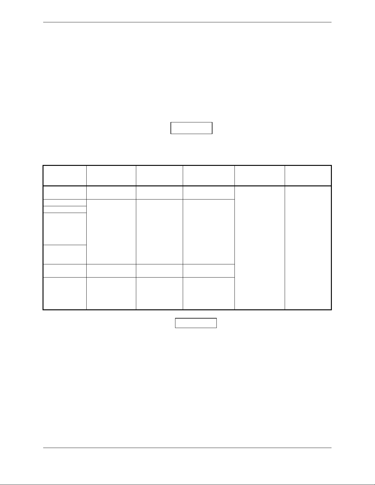
GSU 73 HARDWARE MOD LEVEL HISTORY
The following table identifies hardware modification (Mod) Levels for the GSU 73 LRU. Mod Levels
are listed with the associated service bulletin number, service bulletin date, and the purpose of the
modification. The table is current at the time of publication of this manual (see date on front cover) and is
subject to change without notice.
MOD
LEVEL
SERVICE
BULLETIN
NUMBER
SERVICE
BULLETIN
DATE
PURPOSE OF MODIFICATION
1 N/A N/A Improved HSCM accuracy when using +28V supply
Page xii G3X Installation Manual
Revision A 190-01115-01
Page 15

1 G3X Installation Overview
1.1 Unpacking Unit
Carefully unpack the equipment and make a visual inspection of the unit for evidence of damage incurred
during shipment. If any component of the G3X system is damaged, notify the carrier and file a claim. To
justify a claim, save the original shipping container and all packing materials. Do not return the unit to
Garmin until the carrier has authorized the claim.
Retain the original shipping containers for storage. If the original containers are not available, a separate
cardboard container should be prepared that is large enough to accommodate sufficient packing material
to prevent movement.
1.2 Introduction
This manual provides all of the mechanical and electrical information required for the installation of the
G3X system.
NOTE
The Garmin G3X system includes products like the GDU 37X and the GSU 73 that are
not TSO-certified products and have received no FAA approval or endorsement.
Consequently the G3X system is not suitable for installation in type-certificated aircraft.
The following outline describes the organization of this manual:
Section 1
This section contains a basic overview of the G3X system and interface. A Block
diagram is given to aid in the understanding of the system. This section also contains
generic information that pertains to all components of the G3X system, such as
mounting, wiring, and antenna location.
Section 2
This section describes the mechanical, electrical, and installation aspects of the
GDU 37X.
Section 3
This section describes the mechanical, electrical, and installation aspects of the
GMU 44.
Section 4
This section describes the mechanical, electrical, and installation aspects of the
GSU 73.
Section 5
This section describes the mechanical, electrical, and installation aspects of the
GTP 59.
Section 6
This section describes the mechanical, electrical, and installation aspects for the GPS
and XM antennas.
Section 7
Section 8
This section describes the non-G3X LRU interfaces.
This section contains software, configuration, database, and XM activation
information.
Section 9
This section contains post-installation checkout and calibration procedures for the
G3X.
Section 10
Section 11
This section contains G3X troubleshooting information.
This section contains information for ensuring the unit is suitable to be returned to
service.
Appendix A
Appendix B
Appendix C
Appendix D
Appendix E
G3X Installation Manual – Installation Overview Page 1-1
190-01115-01 Revision A
This section contains pinout information for all G3X LRU’s.
This section contains connector installation instructions.
This section contains G3X Outline and Installation Drawings.
This section contains the G3X Interconnect Drawings.
This section contains the G3X External Interface Drawings.
Page 16
1.3 System Overview
The G3X is an advanced technology avionics suite designed to integrate pilot/aircraft interaction into one
central system. The system combines primary flight instrumentation, aircraft systems instrumentation,
and navigational information, all displayed on one, two, or three color screens. The G3X system is
composed of several sub-units or Line Replaceable Units (LRUs). LRUs have a modular design and can
be installed directly behind the instrument panel or in a separate avionics bay if desired. This design
greatly eases troubleshooting and maintenance of the G3X system. A failure or problem can be isolated
to a particular LRU, which can be replaced quickly and easily. Each LRU has a particular function, or set
of functions, that contributes to the system’s operation. For additional information on LRU functions, see
the applicable section of this manual.
1.3.1 System Architecture
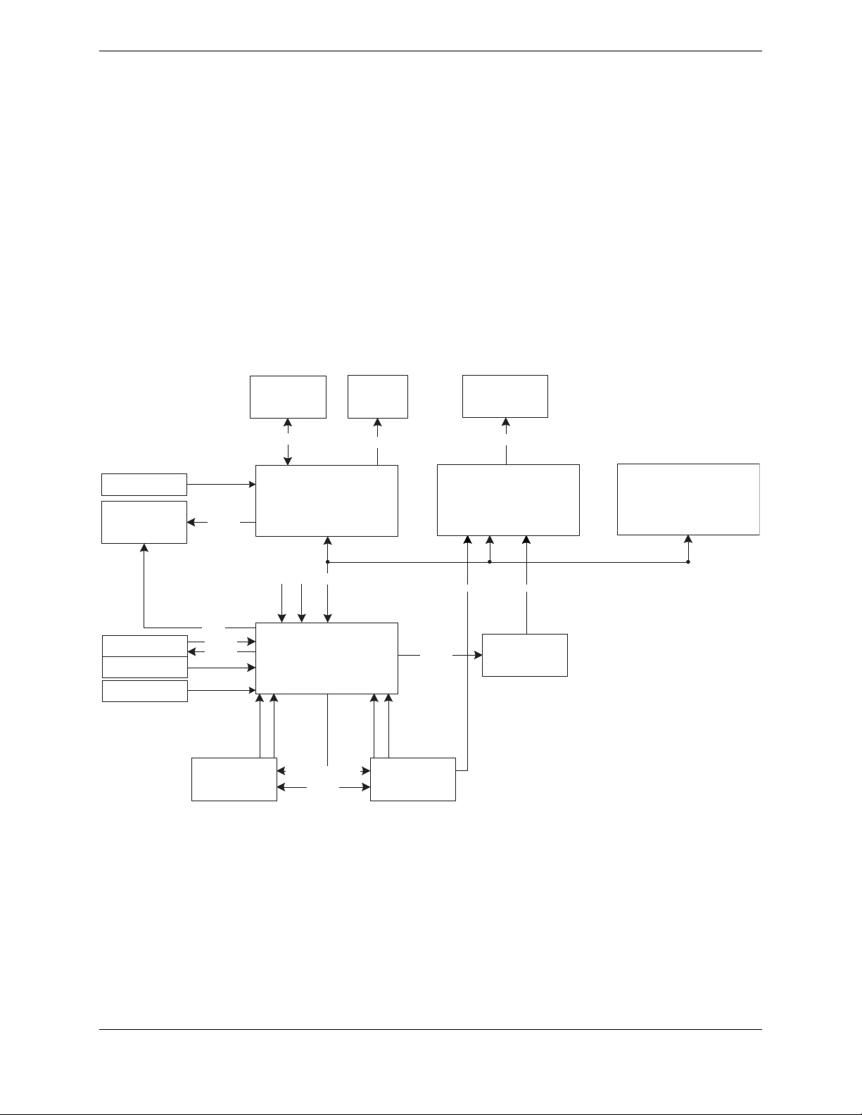
Figure 1-1 illustrates an example block diagram of a G3X installation. The flexibility of system allows
the installer to determine the architecture that best fits each installation.
Config Module
Autopilot
GMU 44
GTP 59
Config Module
RS-232
A429
RS-485
RS-232
GNS
430(W)
SL 30/40
(1, 2)
RS-232
ELT
RS-232
GDU 37X (PFD1)
Pitot
CAN
Static
GSU 73
A429 (GPS)
A429 (NAV)
A429 (AIR DATA)
(1)
RS-232
A429 (GPS)
A429 (NAV)
GNS
430(W)
RS-232
GMA 240
STEREO/MONO AUDIO
GDU 37X (MFD)
RS-232
GTX 330
(1)
Figure 1-1. G3X Interconnect Example
GDU 37X (PFD2)
RS-232
Notes:
(1) Maximum of 2 COM/NAV units installed.
(2) GDU 37X to SL40 is TX only.
Page 1-2 G3X Installation Manual –Installation Overview
Revision A 190-01115-01
Page 17
1.4 General G3X LRU Specifications
1.4.1 Garmin LRU Part Numbers
Table 1-1. G3X LRU Part Numbers
LRU Unit Only Part Number Assembly Part Number
GDU 370 Americas DB 011-01747-15 010-00667-15
GDU 370 Atlantic DB 011-01747-20 010-00667-20
GDU 370 Pacific DB 011-01747-35 010-00667-35
GDU 375 Americas DB 011-01747-30 010-00667-25
GMU 44 011-00870-10 010-00296-10*
GSU 73 011-01817-00 010-00691-00*
GTP 59 011-00978-00* NA
*Included in G3X LRU Kit (K10-00016-00)
Table 1-2. Contents of GDU 37X Assembly (010-00667-XX)
Item Garmin P/N Quantity
GDU 37X 011-01747-XX 1
GDU 37X Connector Kit 011-01921-00 1
GDU 37X Nutplate
SD Card, Dummy 145-00561-00 1
Important Safety and Product Information 190-00720-50 1
GDU 37X Quick Reference Guide 190-01055-00 1
Jeppesen Free Single Update 190-10003-03 1
115-01054-00 1
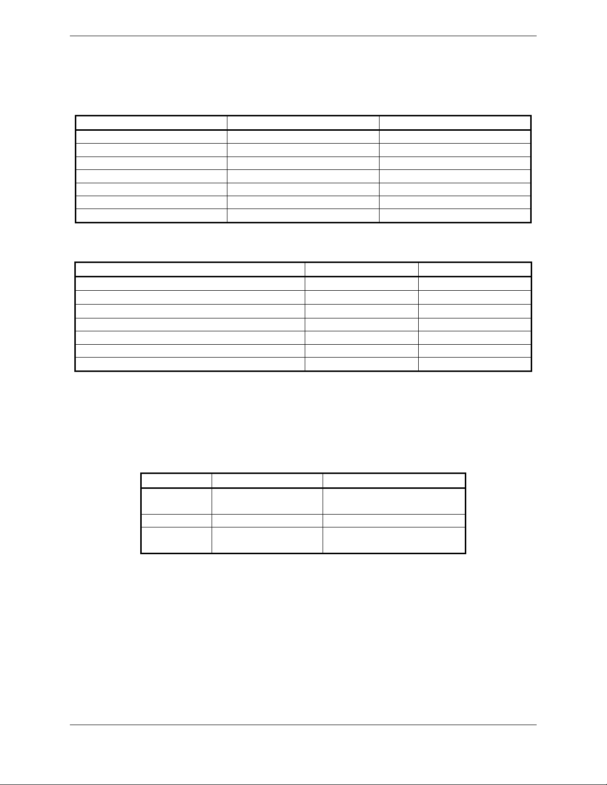
1.4.2 Power Specifications
All LRUs are capable of operating at either 14 or 28 VDC. Table 1-3 lists current draw specifications.
Table 1-3. G3X LRU Power Requirements
LRU Supply Voltage Current Draw
GDU 37X 10-29 Vdc
GMU 44 12Vdc (from GSU 73) Inc. in GSU Current Draw
GSU 73 10-29 Vdc
1.10 Amp @ 14Vdc
0.55 Amp @ 28Vdc
1.75 Amp @ 14Vdc (Max)
0.80 Amp @ 28Vdc (Max)
G3X Installation Manual – Installation Overview Page 1-3
190-01115-01 Revision A
Page 18
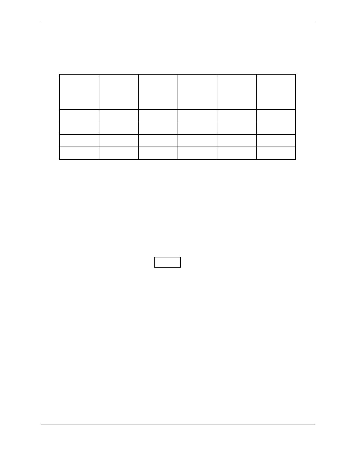
1.4.3 Physical Specifications
All width, height, and depth measurements are taken with unit rack (if applicable) and connectors.
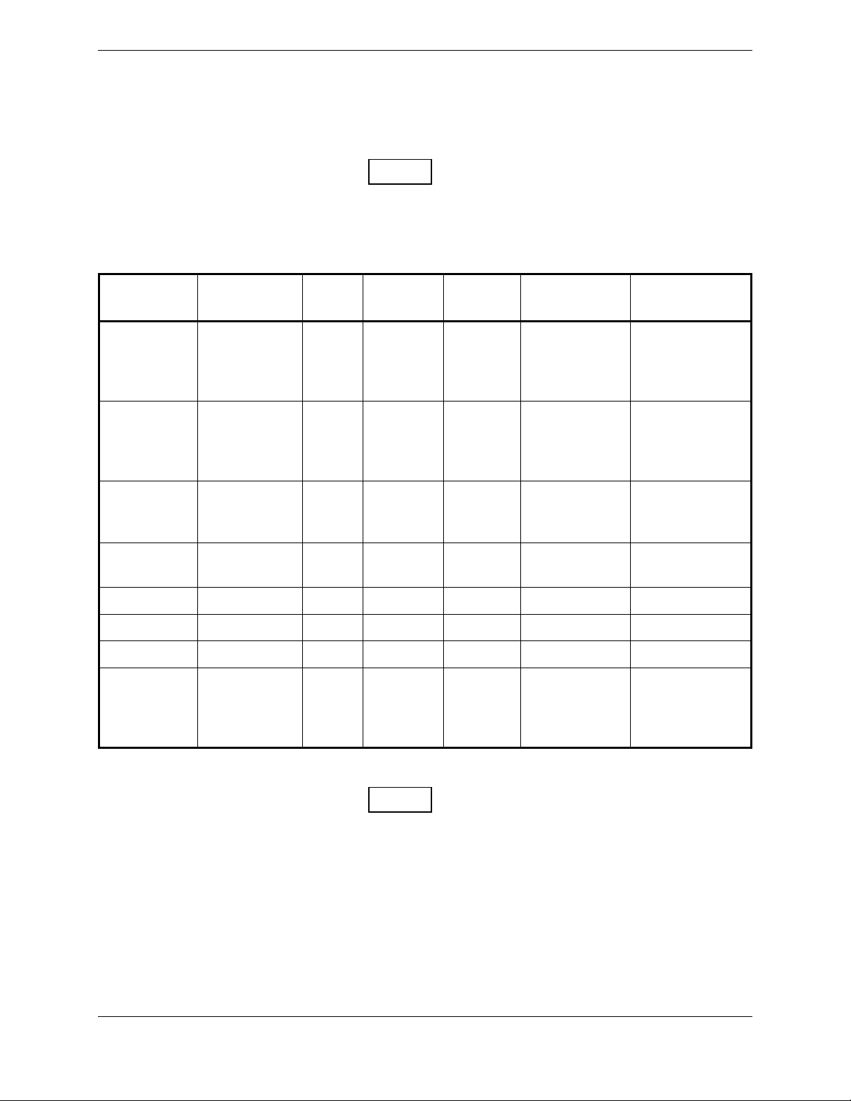
Table 1-4. G3X LRU Physical Specifications
LRU Width Height
GDU 370
GDU 375
GMU 44
GSU 73
6.04 inches
(153.4 mm)
6.04 inches
(153.4 mm)
N/A
5.50 inches
(139.8 mm)
7.83 inches
(198.8 mm)
7.83 inches
(198.8 mm)
2.10 inches
(5.33 cm)
3.96 inches
(100.6 mm)
Depth
(GMU 44
Diameter,
including
flange*)
3.41 inches
(86.7 mm)
3.41 inches
(86.7 mm)
*3.35 inches
(85.1 mm)
7.33 inches
(186.2 mm)
Unit Weight
1.6 lbs
(0.713 kg)
1.7 lbs
(0.753 kg)
0.35 lbs.
(0.16 kg)
3.1 lbs
(1.41 kg)
Unit Weight
w/Nutplate
& Connector
Weight
1.8 lbs
(0.803 kg)
1.9 lbs
(0.843 kg)
0.50 lbs.
(0.23 kg)
3.5 lbs
(1.59 kg)
1.4.4 Cooling Requirements
While no forced cooling air is required for the G3X system, it is highly recommended that the air behind
the panel be kept moving (by ventilation or a fan).
• No cooling air is required for the GDU 37X
• No cooling air is required for the GMU 44
• No cooling air is required for the GSU 73, however the GSU 73 should be mounted in a location
that provides adequate airflow to comply with the maximum outer case temperature listed in
Section 4.
NOTE
Avoid installing the G3X LRUs near heat sources. If this is not possible, ensure that
additional cooling is provided. Allow adequate space for installation of cables and
connectors. The installer will supply and fabricate all of the cables. All wiring should be
in accordance with FAA AC 43.13-1B and AC 43.13-2A.
Page 1-4 G3X Installation Manual –Installation Overview
Revision A 190-01115-01
Page 19

1.5 Installation Requirements
One GDU 37X assembly (listed in Table 1-1) is required, dependent upon customer’s desired database
region. Each GDU 37X (010-00667-XX) comes with all equipment needed for installation.
1.5.1 Required Accessories
The following kits are required for the installation of the G3X.
Table 1-5. Contents of G3X Installation Kit (K10-00017-00)
Item Garmin P/N Quantity
GMU 44, Connector Kit 011-00871-00 1
Config Module w/EEPROM, Jackscrew 011-00979-20 1
Config Module w/Sockets, Jackscrew 011-00979-22 1
Thermocouple Kit 011-00981-00 1
GSU 73, Connector Kit, P9731 011-01818-00 1
GSU 73, Connector Kit, P9732 011-01818-01 1
G3X, Supplemental Parts 011-02347-00 1
GMU 44, Install Rack, Modified 115-00481-10 1
Table 1-6. Contents of G3X LRU Kit (K10-00016-00)
Item Garmin P/N Quantity
GMU 44, Unit Only 010-00296-10 1
GSU 73, Unit Only 010-00691-00 1
GTP 59, Unit Only 011-00978-00 1
1.6 Mounting
Refer to Section 2 through Section 6 for specific mounting instructions for each component of the G3X,
and to Appendix A for Outline & Installation Drawings.
1.7 Wiring/Cabling Considerations
Use MIL-W-22759/16 (or other approved wire) AWG #24 or larger wire for all connections unless
otherwise specified. The supplied standard pin contacts are compatible with up to AWG #22 wire. In
cases where some installations have more than one LRU sharing a common circuit breaker, sizing and
wire gauge is based on aircraft circuit breaker layout, length of wiring, current draw on units, and internal
unit protection characteristics. Do not attempt to combine more than one unit on the same circuit breaker.
RG400 or RG142 coaxial cable with 50 Ω nominal impedance and meeting applicable aviation
regulations should be used for the installation.
G3X Installation Manual – Installation Overview Page 1-5
190-01115-01 Revision A
Page 20
1.7.1 Wiring Harness Installation
Allow adequate space for installation of cables and connectors. Ensure that routing of the wiring does not
come in contact with sources of heat, RF or EMI interference. Analog Input wires routed too close to
spark plugs, plug wires, or magnetos may result in erratic readings.
The installer shall supply and fabricate all of the cables. Required connectors, etc. are provided with the
G3X Installation Kit (K10-00017-00). Electrical connections are made through D subminiature
connectors for the GDU 37X and GSU 73 units, and through a round 9-pin connector for the GMU 44.
Appendix A defines the electrical characteristics of all input and output signals. Required connectors and
associated hardware are supplied with the connector kit..
CAUTION
Check wiring connections for errors before connecting any wiring harnesses. Incorrect
wiring could cause internal component damage.
Table 1-7. Pin Contact and Crimp Tools Part Numbers
LRU Contact Type
GDU 37X
GSU 73
GTP 59
011-00979-20
(Config
module
w/EEPROM
kit)
011-00981-00
(thermocouple
kit)
GMU 44
011-00979-22
(Config
module
w/Sockets &
Jackscrew kit)
Socket, Mil
Crimp, Size 20
Pin, Mil Crimp,
Size 22D
Socket, Mil
Crimp, Size 20
Socket, Mil
Crimp, Size 20,
26-30 AWG
1. Insertion/Extraction tools from ITT Cannon are all plastic; others are plastic with metal tip.
2. Non-Garmin part numbers shown are not maintained by Garmin and consequently are subject
to change without notice.
Garmin
Contact Part
Number
336-00094-00
336-00021-00
336-00022-00
336-00022-01
Recommended
Positioner
M22520/2-08,
Daniels K13-1
Positronic P/N
9502-4,
ITT P/N
M22520/2-09,
Daniels P/N K42
M22520/2-08,
Daniels K13-1
Positronic P/N
9502-5
NOTES
Recommended
Insertion/
Extraction Tool
M81969/1-04
for size 22D
pins and
M81969/1-02
for size 20 pins
Recommended
Hand Crimping
Tool
M22520/2-01
Page 1-6 G3X Installation Manual –Installation Overview
Revision A 190-01115-01
Page 21
1.7.2 Cable Location Considerations
Use cable meeting the applicable aviation regulation for the interconnect wiring. Any cable meeting
specifications is acceptable for the installation. When routing cables, observe the following precautions:
• All cable routing should be kept as short and as direct as possible.
• Check that there is ample space for the cabling and mating connectors.
• Avoid sharp bends in cabling.
• Avoid routing near aircraft control cables.
• Avoid routing cables near power sources (e.g., 400 Hz generators, trim motors, etc.) or near
power for fluorescent lighting.
• Route the GPS antenna cable as far as possible away from all COM transceivers and antenna
cables.
1.7.3 Cable Installation
1. Route the coaxial cable to the unit location. Secure the cable in accordance with good aviation
practices.
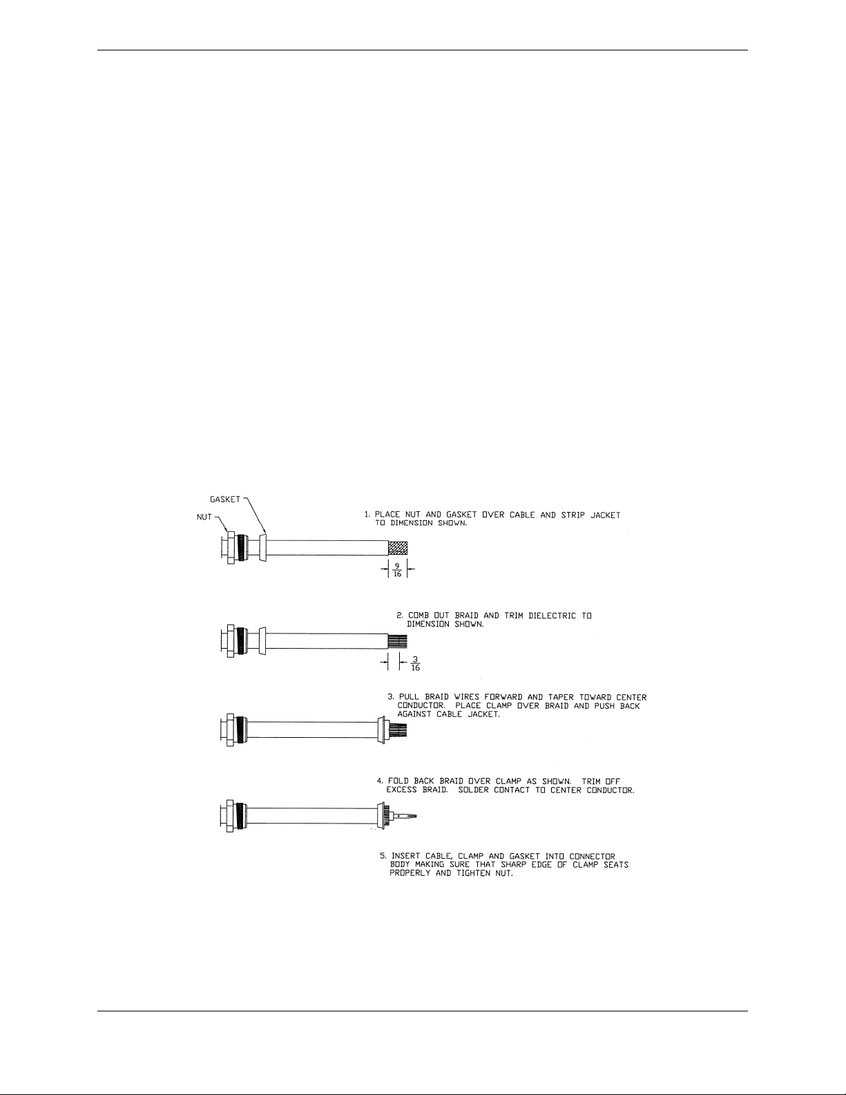
2. Trim the coaxial cable to the desired length and install the BNC connector (330-00087-00) per
the cabling instructions on Figure 1-2. If the connector is provided by the installer, follow the
connector manufacturer’s instructions for cable preparation.
Figure 1-2. Coaxial Cable Installation
3. Contacts for the 50, 62, and 78 pin connectors must be crimped onto the individual wires of
the aircraft wiring harness. Table 1-7 lists contact part numbers (for reference) and
recommended crimp tools.
G3X Installation Manual – Installation Overview Page 1-7
190-01115-01 Revision A
Page 22

1.7.4 Backshell Assemblies
Connector kits include backshell assemblies. The backshell assembly houses the configuration module
and a thermocouple reference junction (if applicable, see Appendix D). Garmin’s backshell connectors
give the installer the ability to quickly and easily terminate shield grounds at the backshell housing. The
instructions needed to install the Jackscrew Backshell, Configuration Module, and Thermocouple are
located in Appendix B.
NOTE
The GDU 37X rear connector (J3701) is electrically isolated. For installations using
shielded cables, a ground pin must be tied to the connector shell.
Page 1-8 G3X Installation Manual –Installation Overview
Revision A 190-01115-01
Page 23
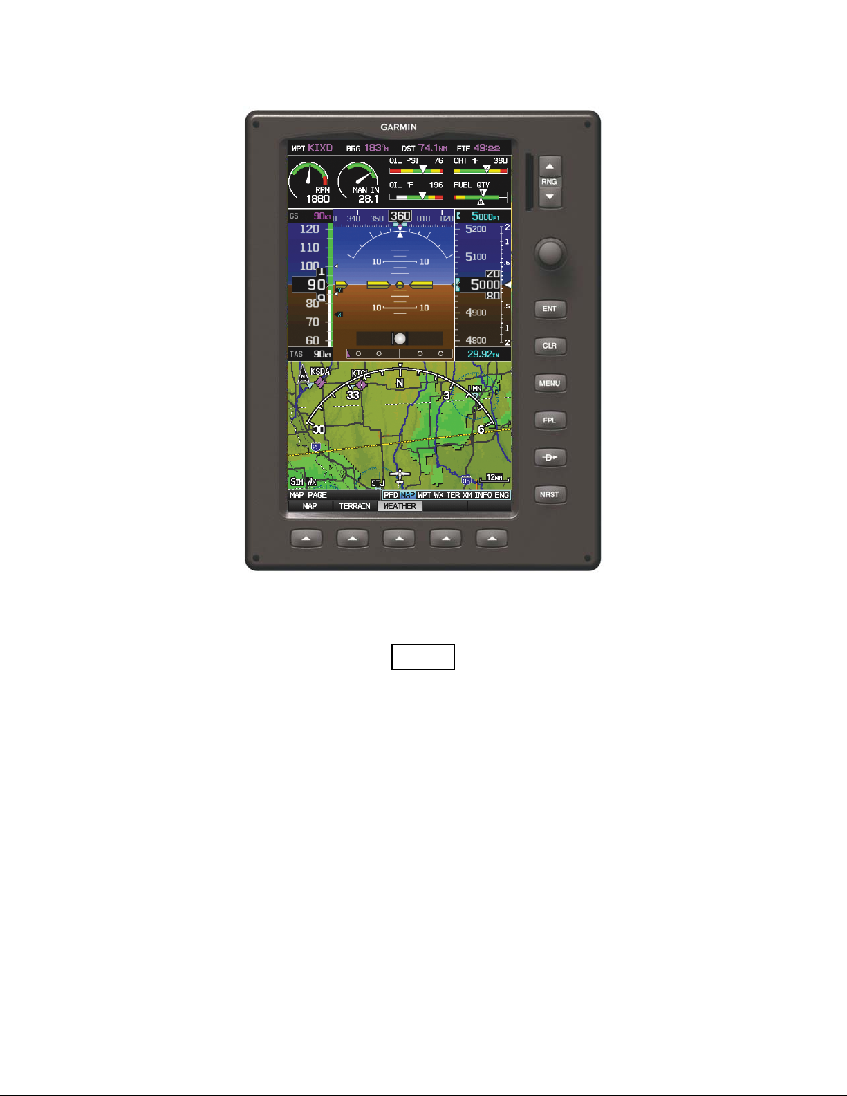
2 GDU 37X
Figure 2-1. GDU 37X Unit View
2.1 Equipment Description
NOTE
There is no TSO/ETSO applicable to the GDU G37X.
The GDU 37X provides a central display and user interface for the G3X system. The display is mounted
flush to the aircraft instrument panel using four #6 screws. The GDU 37X is available in two models,
GDU 370 and GDU 375. The GDU 370 is a Garmin Display Unit with a VFR WAAS-GPS receiver.
The GDU 375 provides these same features plus an XM receiver.
2.1.1 Navigation Functions
• Display of position and ground speed
• Display of stored navigation and map databases
• Area navigation functions using the determined position/velocity and stored navigation data
• Advisory approach navigation functions and associated databases
G3X Installation Manual – GDU 37X Page 2-1
190-01115-01 Revision A
Page 24
2.1.2 Interface Summary
The GDU 37X uses CAN and RS-232 communications interfaces. The GDU 37X communicates with the
following Garmin LRUs:
• Other GDU 37X
• GSU 73
• SL30 Nav/Comm Transceiver
• SL40 Comm Transceiver
• GNS 400/500 Series Units
• GTX 327/330 Transponder
2.2 Electrical Specifications
2.2.1 Electrical Characteristics
Table 2-1. GDU 37X Supply Voltages
Characteristics Specifications
Power Requirements 14/28 VDC
2.2.2 Power Consumption
Table 2-2. GDU 37X Power Requirements
LRU 14V (Maximum) 14V (Typical) 28V (Maximum) 28V (Typical)
GDU 370
GDU 375
15W, 1.10 Amp 8.5W, .600 Amp 15W, 0.540 Amp 8.5W, .300 Amp
15W, 1.10 Amp 9.5W, .675 Amp 15W, 0.540 Amp 9.25W, .330 Amp
2.2.3 GPS Specifications
The GDU 37X uses a high-sensitivity GPS receiver that continuously tracks and uses up to 12 satellites to
compute and update its position.
Table 2-3. GDU 37X GPS Specifications
Characteristics Specifications
Acquisition Time a) Warm Start (position known to 10 nm, time known to 10
minutes, with valid almanac and ephemeris): Less than 5
seconds
b) Cold Start (position known to 300 nm, time known to 10
minutes, with valid almanac): Less than 45 seconds
c) AutoLocate™ (with almanac, without initial position or
time): Less than 60 seconds
Update Rate 5/second, continuous
Positional Accuracy <10 meters
Antenna Power Supply Voltage (4.5 to 5.0), current (50 mA max)
Page 2-2 G3X Installation Manual – GDU 37X
Revision A 190-01115-01
Page 25
2.2.4 Antennas
Table 2-4 lists Garmin and non-Garmin antennas currently supported by the GDU 37X. Refer to Section
6 for Garmin antenna installation information. For non-Garmin antennas, follow the manufacturer’s
installation instructions.
NOTE
Only a single GPS antenna is required for installations using more than
one GDU 37X unit, as the GDU 37X will “share” the GPS information
with all GDU 37X units.
Table 2-4. GDU 37X Supported Antennas
Model Mount Style
Comant
2480-201
VHF/GPS
[1]
Comant
420-10 XM
only
Antenna
Screw
Mount,
Teardrop
Footprint
Screw
Mount,
ARINC 743
Footprint
Conn
Type
BNC
TNC
Antenna
Type
VHF
COM,
GPS
Mfr
Comant CI 2480-201 N/A
Antenna Part
Number
TNC XM Comant CI 420-10 N/A
Garmin Order
Number
Suction Cup,
GA 26C
Magnetic or
BNC GPS Garmin 011-00149-04 010-10052-04
Flange Mt
GA 26XM
Ground
Plane Mt
TNC XM Garmin 013-00268-10 010-11373-00
GA 55 Stud Mount TNC XM Garmin 011-01033-00 010-10600-01
GA 55A ARINC 743 TNC XM Garmin 011-01153-00 010-10598-00
GA 56 Stud Mount BNC GPS Garmin 011-00134-00 010-10040-01
Screw
GA 57X
[2]
Mount,
ARINC 743
BNC
TNC
GPS
XM
Garmin 011-01032-10 010-11370-10
Footprint
[1] The GPS antenna connec tor is TNC type. The VHF COM antenna connector is BNC type.
NOTE
The GPS antenna should provide a gain of 16 to 25dB, and requires a
4.5V to 5V supply voltage that can provide 50mA max.
2.3 Environmental Specifications
The GDU 37X has an Operating Temperature Range of -20°C to +60°C.
G3X Installation Manual – GDU 37X Page 2-3
190-01115-01 Revision A
Page 26
2.4 Installation Requirements
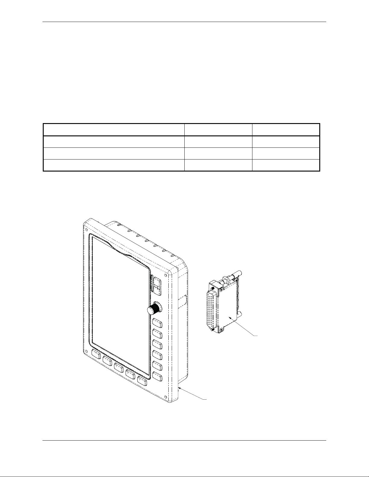
2.4.1 Accessories
The GDU 37X Connector Kit is provided with the GDU 37X unit and is required to install the unit
(Figure 2-2). The GDU 37X Nutplate (115-01054-00) is also supplied with the unit to reinforce the panel
cutout in thin panel installations.
The contents of the GDU 37X Connector Kit are listed in Table 2-5. One kit is required for each GDU
37X installed.
Table 2-5. Contents of GDU 37X Connector Kit (011-01921-00)**
Item Garmin P/N Quantity
Sub-Assy,bkshl w/Hdw,Jackscrew 011-01855-04 1
Conn, Rcpt,D-Sub, Crimp Socket, C 330-00625-50 1
Contact, Sckt, D-Sub, Crimp, Size 20 336-00094-00 20
2.4.2 Additional Equipment
A 3/32” hex drive tool is required to secure the GDU 37X to the panel as described in Section 2.7 Unit
Installation.
CONNECTOR KIT
011-01921-00
GDU 37x UNIT
011-01747-( )
Figure 2-2. GDU 37X Mounting Accessories
Page 2-4 G3X Installation Manual – GDU 37X
Revision A 190-01115-01
Page 27

2.5 Installation Considerations
Fabrication of a wiring harness is required. Sound mechanical and electrical methods and practices are
recommended for installation of the GDU 37X. Refer to Section 1.6 for wiring considerations and to
Appendix A for pinouts.
Connector kits include backshell assemblies. Garmin’s backshell connectors give the installer the ability
to quickly and easily terminate shield grounds and install a configuration module (PFD1 only) at the
backshell housing. The instructions needed to assemble the backshell connector w/Shield Block
grounding system and configuration modules are located in Appendix B.
NOTE
The GDU 37X rear connector (J3701) is electrically isolated. For
installations using shielded cables, a ground pin must be tied to the
connector shell.
2.6 Mounting Requirements
Refer to Appendix C for outline and installation drawings.
2.7 Unit Installation
The GDU 37X is installed by holding the unit flush with the instrument panel and fastening the four
captured 3/32” hex socket head screws to the panel as shown in Figures C-1.1 and C-1.2.
2.8 Maintenance
Maintenance of the GDU 37X is “on condition” only. Periodic maintenance of the GDU 37X is not
required. Instructions for Continued Airworthiness (ICA) are not required for this product under 14 CFR
Part 21 since the GDU 37X has received no FAA approval or endorsement.
G3X Installation Manual – GDU 37X Page 2-5
190-01115-01 Revision A
Page 28
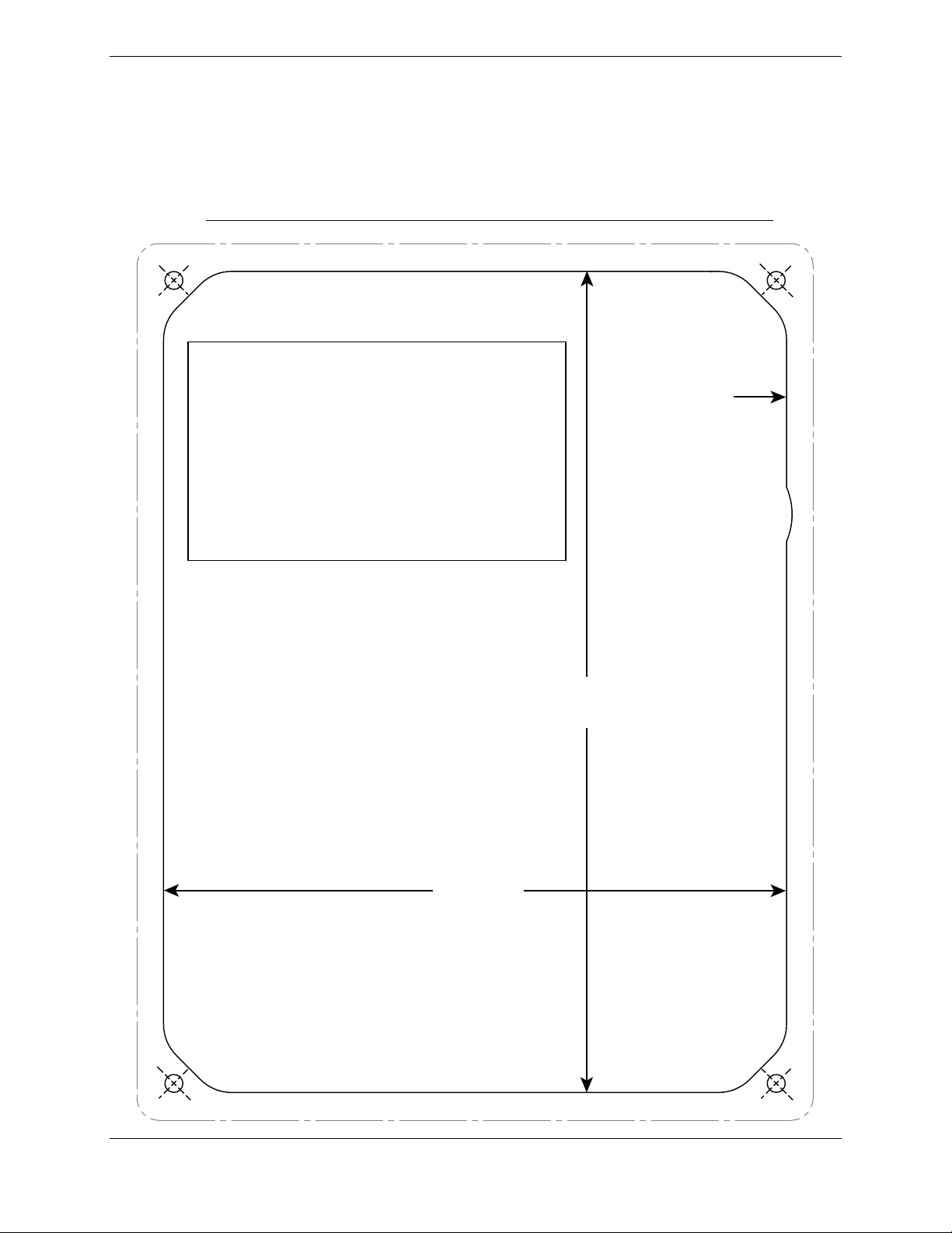
2.9 Panel Cutout Template
The below drawing can be used as a template when marking the panel for cutout. Dimensions below are
to verify accuracy of printout only, see Figure C-1.2 for complete dimensions.
GDU 37X PANEL CUTOUT TEMPLATE
IMPORTANT!
Ensure the Page Scaling setting
is set to NONE when printing
this page. Verify dimensions
of printed template are
accurate before cutting panel.
7.33 in
[186.2 mm]
Cut out panel
to inside line
5.57 in
[141.4 mm]
For corner holes, center punch and drill
(#36) / tap (6/32) to create threaded holes
OR
drill out with 25 drill bit and use Garmin
nut-plate P/N 115-01054-00
Page 2-6 G3X Installation Manual – GDU 37X
Revision A 190-01115-01
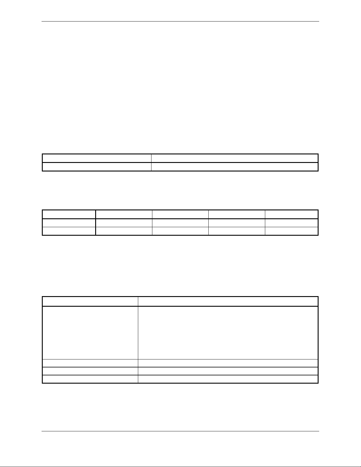
Page 29
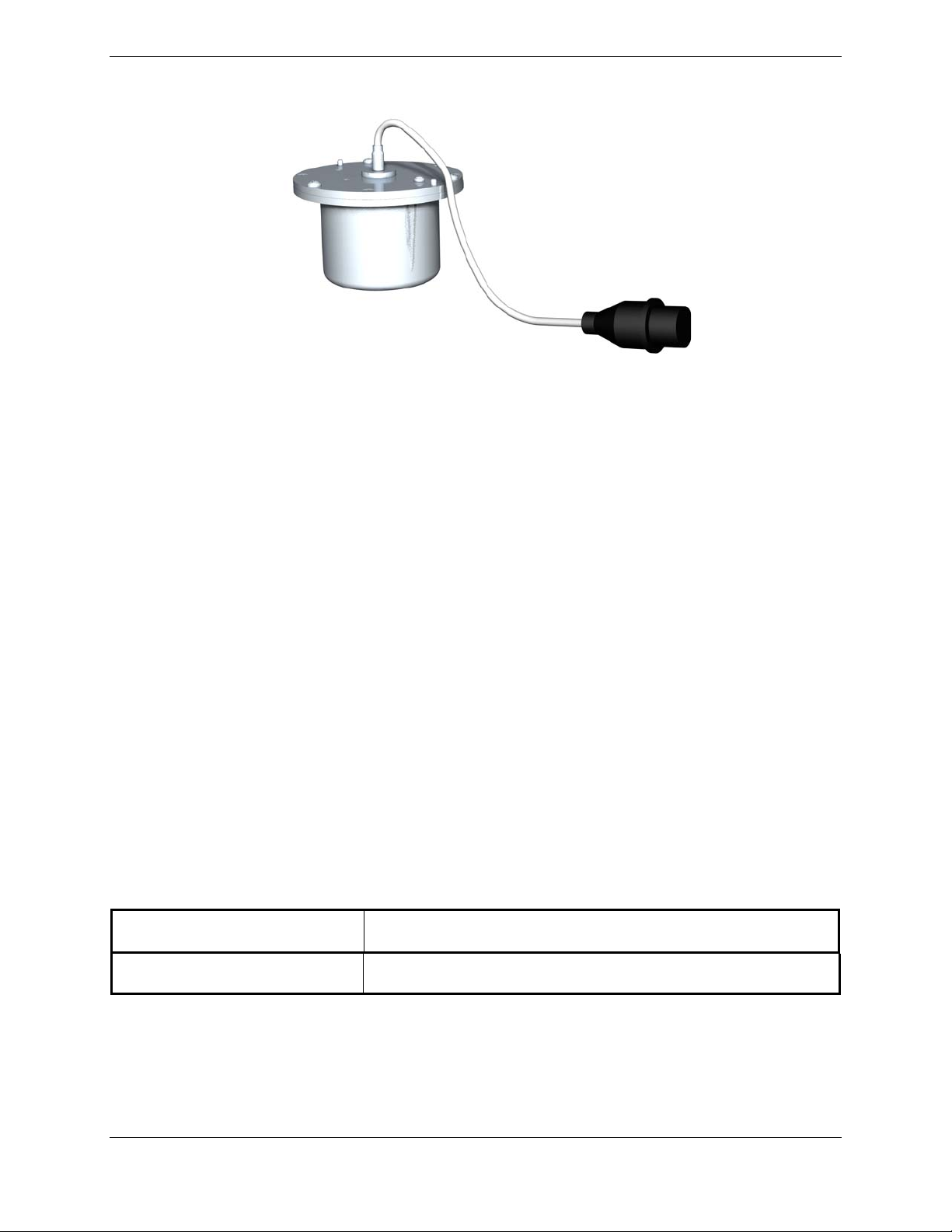
3. GMU 44
Figure 3-1. GMU 44 Unit View
3.1 Equipment Description
The Garmin GMU 44 Magnetometer is a remote mounted device that interfaces with a Garmin GSU 73 to
provide flight attitude and heading data for flight instrumentation.
An Attitude and Heading Reference System combines the functions of a Vertical Gyro and a Directional
Gyro to provide measurement of Roll, Pitch and Heading angles. The Garmin ADAHRS and
magnetometer replace traditional rotating mass instruments.
Using long-life solid-state sensing technology, the GMU 44 Magnetometer uses magnetic field
measurements to create an electronically stabilized AHRS.
The GMU 44 magnetometer provides magnetic information to support the function of the GSU 73. The
GSU 73 provides operating voltage to the GMU 44 Magnetometer.
3.1.1 Interface Summary
The following is an interface summary for the GMU 44.
• GMU 44 to GSU 73 Interface: Power, RS-232, RS-485 (19,200 baud)
3.2 Electrical Specifications
Table 3-1. GMU 44 Electrical Specifications
Specification Characteristic
Power Requirements
G3X Installation Manual – GMU 44 Page 3-1
190-01115-01 Revision A
Supply Voltage: 14/28 VDC. See Table 1-3 for current
specifications.
Page 30

3.3 Environmental Specifications
Table 3-2 lists general environmental specifications.
Table 3-2. GMU 44 Environmental Specifications
Specification Characteristic
Regulatory Compliance RTCA/DO-160D Environmental Conditions and
EUROCAE/ED-14D
Unit Software RTCA/DO-178B Level B
Operating Temperature
Range
-55° C to +70° C
Altitude 55,000 Feet
3.4 GMU 44 TSO/ETSO Compliance
Table 3-3. TSO/ETSO Compliance
Applicable
Custom Logic
Device Part
Numbers
All
006-C0048-0(_)
Function
Direction Instrument,
Magnetic (Gyroscopically
Stabilized)
TSO/ETSO/SAE/
RTCA/EUROCAE
TSO-C6d
ETSO-C6d
AS8013A
Category
Applicable LRU
SW Part
Numbers
All
006-B0224-(__)
except
006-B0224-Z(_)
3.4.1 TSO/ETSO Deviations
The following table provides a list of applicable TSO and SAE deviations for the GMU 44.
Table 3-4. TSO/ETSO Deviations
TSO Deviation
TSO-C6d
(GMU 44)
ETSO-C6d
(GMU 44)
1. Garmin was granted a deviation from TSO-C6d to use RTCA DO-160D instead of RTCA
DO-160B as the standard for Environmental Conditions and Test Procedures for Airborne
Equipment.
2. Garmin was granted a deviation from TSO-C6d to use RTCA DO-178B instead of RTCA
DO-178A to demonstrate compliance for the verification and validation of the computer
software.
3. Garmin was granted a deviation from TSO-C6d to use SAE AS 8013A instead of SAE
AS 8013 as the Minimum Performance Standard.
4. Garmin was granted a deviation from TSO-C6d to list this secondary TSO in the
Installation Manual rather than on the article itself.
5. Garmin was granted a deviation from TSO-C6d to list the DO-178B software level in the
Installation Manual rather than on the article itself.
1. Garmin was granted a deviation from ETSO-C6d to use RTCA DO-160D instead of SAE
AS 8013 as the standard for Environmental Conditions and Test Procedures for Airborne
Equipment.
2. Garmin was granted a deviation from ETSO-C6d to use SAE AS 8013A instead of SAE
AS 8013 as the Minimum Performance Standard.
Page 3-2 G3X Installation Manual – GMU 44
Revision A 190-01115-01
Page 31

3.5 Installation Requirements
3.5.1 Equipment Available
Table 3-5. GMU 44 Part Numbers
Model
GMU 44 010-00296-10* 011-00870-10 No
*Included in G3X LRU Kit (K10-00016-00)
Catalog Part
Number
Table 3-6. GMU 44 Accessories
Unit Part Number Installation Rack
Item Garmin P/N Quantity
Sub Assy, Connector Kit, GMU 44 011-00871-00** 1
GMU 44 Universal Mount*** 011-01779-01 1 (optional)
Installation Rack, GMU 44 115-00481-10** 1
**Included in G3X Installation Kit (K10-00017-00)
***Refer to AHRS Magnetometer Installation Considerations (190-01051-00) from www.garmin.com
3.6 Installation Considerations
NOTE
If the requirements listed in Table 3-7 cannot be met, a magnetometer
interference test must be performed to ensure proper operation of the
G3X system. Refer to the AHRS/Magnetometer Installation
Considerations document (190-01051-00) available from the Garmin
website (
The following guidelines describe proper mechanical installation of the Garmin GMU 44 Magnetometer.
The guidelines include requirements for proper location selection in the aircraft, requirements for
supporting structure and mechanical alignment and restriction on nearby equipment.
Fabrication of a wiring harness is required. Sound mechanical and electrical methods and practices are
required for installation of the GMU 44. Refer to Section 1.6 for wiring considerations and to Appendix
A for pinouts.
The instructions needed to assemble the circular connector are located in Appendix B.
The GMU 44 is an extremely sensitive three-axis magnetic sensor. It is more sensitive to nearby
magnetic disturbances than a flux gate magnetometer. For this reason, when choosing a mounting
location for the GMU 44, observe the following distances from objects or devices that can disturb the
magnetic field. Table 3-7 specifies required distances from magnetic disturbances for GMU 44 location.
www.garmin.com).
G3X Installation Manual – GMU 44 Page 3-3
190-01115-01 Revision A
Page 32

Table 3-7. Required Distance from Magnetic Disturbances
Disturbance Source Minimum Distance from GMU 44
Electric motors and relays, including servo motors 10 feet (3.0 meters)
Ferromagnetic structure greater than 1 kg total
(iron, steel, or cobalt materials, especially landing
gear structure)
8.2 feet (2.5 meters)
Ferromagnetic materials less than 1 kg total, such
as control cables
Any electrical device drawing more than 100 mA
current
3 feet (1.0 meter)
3 feet (1.0 meter)
Electrical conductors passing more than 100 mA
current [(must be twisted shielded pair if within 10
3 feet (1.0 meter)
feet (3.0 meters)]
Electrical devices drawing less than 100 mA current 2 feet (0.6 meter)
Magnetic measuring device (e.g. installed flux
gates, even if unpowered)
2 feet (0.6 meter)
Electrical conductors passing less than 100 mA
current [(must be twisted shielded pair if within 10
1.3 feet (0.4 meter)
feet (3.0 meters)]
Ensure that any electrical conductor that comes within 10 feet (3.0 meters) of the GMU 44 is installed as a
twisted shielded pair, not a single-wire conductor. (If possible, the shield should be grounded at both
ends.)
Use nonmagnetic materials to mount the GMU 44, and replace any magnetic fasteners within 0.5 meter
with nonmagnetic equivalents (e.g. replace zinc-plated steel screws used to mount wing covers or
wingtips with nonmagnetic stainless steel screws).
In general, wing mounting of the GMU 44 magnetometer is strongly preferred. Fuselage mounting is
strongly discouraged because of numerous potential disturbances that interfere with accurate operation.
Mechanical mounting fixtures for the GMU 44 must be rigidly connected to the aircraft structure. Use of
typical aircraft-grade materials and methods for rigid mounting of components is acceptable, so long as
adequate measures are taken to ensure a stiffened mounting structure.
Align the GMU 44 mounting rack to within 3.0° of the aircraft level reference in pitch and roll.
Align the GMU 44 mounting rack’s forward direction to within 0.5° in heading of the aircraft forward
direction (longitudinal axis). If it is not possible to guarantee this accuracy, installation alignment to
within 2.5° in heading is acceptable in combination with a post-installation heading alignment of the
aircraft to a precise heading to determine and set a heading offset. The heading offset procedure is
described in Section 8.3.4.
It is strongly preferred that the GMU 44 alignment is within 0.5° of the aircraft longitudinal axis, rather
than using the heading offset procedure.
Page 3-4 G3X Installation Manual – GMU 44
Revision A 190-01115-01
Page 33

3.6.1 Consideration for Wing Grounded Lighting Fixtures
The following installation practices are recommended if the required GMU 44 mounting bracket is
located in the wing.
1. The wing tip lights should not have a power ground referenced to the chassis of the light
assembly that would then be referenced back to the airframe ground via the light assembly
mounting.
2. A dedicated power ground should be used and returned as a twisted pair with the power source
back into the fuselage for a wing mounted GMU 44.
These installation practices will prevent magnetically interfering currents from flowing in the wing skin
that encloses the GMU 44. Electrically isolating the light assembly should not be used as an alternative to
item 1 above, unless the isolated light assembly has been analyzed for adequate protection against direct
attachment of lightning.
Refer to Appendix C for outline and installation drawings.
3.7 GSU 73/GMU 44 Interconnect Harness Fabrication Instructions
Table 3-8 lists parts needed for the GMU 44 interconnect harness. Some of the parts for installation are
included in the GMU 44 Connector Installation Kit. Other parts are provided by the installer. Reference
numbers refer to item bubble numbers shown in Figure C-2.4.
Table 3-8. Parts Needed for GMU 44 Installation
Figure B-2.4 Ref Description
1
2 Shield Extension Wire 0 M22759/16-22
3, 4, 9 GMU 44 Connector Kit** 1 011-00871-00
5 3-Conductor Cable 0 M27500-22TE3T14
6 2-Conductor Cable 0 M27500-22TE2T14
**Included in G3X Installation Kit (K10-00017-00)
Table 3-9 lists material in the GMU 44 connector kit and the associated reference number, as shown in
Figure C-2.4. The GMU 44 magnetometer has an attached pigtail with male polarity. The harness
connector for the GMU 44 has female polarity.
Table 3-9. GMU 44 Connector Kit (011-00871-00)** Contents, Reference Figure C-2.4
Item Garmin P/N Quantity Figure C-2.4 Ref
Screw,6-32x.250,PHP,BR,w/Nyl 211-60037-08 3 9
Conn,Circular,Female,9 Ckt 330-00360-00 1 4
Shield Termination
(method optional)
Qty.
Included
0
GPN or MIL Spec
Parts used depend on method
chosen
Backshell,Circular,Kit,SS 330-90005-01 1 4
Cont,Sckt,Mil Crp,Size 20 336-00022-00 10 3
**Included in G3X Installation Kit (K10-00017-00)
G3X Installation Manual – GMU 44 Page 3-5
190-01115-01 Revision A
Page 34

3.8 Mounting Instructions
After evaluation of the mounting location has been completed and ensuring that requirements are met,
assemble the GMU 44 mounting plate kits according to the dimensions given in Appendix C. Install the
unit assemblies.
Mount the GMU 44 to its mounting plate, taking care to tighten the mounting screws firmly. Use of nonmagnetic tools (e.g. beryllium copper or titanium) is recommended when installing or servicing the
GMU 44. Do not
The metal components in the GMU 44's connector may slightly affect the magnetic field sensed by the
GMU 44. Place the connector at least 2 inches from the body of the GMU 44 to minimize this effect.
After attaching the GMU 44's connector to its mate in the aircraft wiring, secure the connector in place
using good installation practices. This will ensure that any remaining magnetic effect can be
compensated for using Calibration Procedure C: Magnetometer Calibration (Section 9.3.3).
use a screwdriver that contains a magnet when installing or servicing the GMU 44.
NOTE
If the GMU 44 is ever removed, the anti-rotation properties of the
mounting screws must be restored. This may be done by replacing the
screws with new Garmin PN 211-60037-08. If original screws must be
re-used, coat screw threads with Loctite 242 (blue) thread-locking
compound, Garmin PN 291-00023-02, or equivalent. Important:
Mounting screws must be brass.
3.9 Maintenance
Maintenance of the GMU 44 is ‘on condition’ only. Periodic maintenance of the GMU 44 is not required.
Page 3-6 G3X Installation Manual – GMU 44
Revision A 190-01115-01
Page 35

4 GSU 73
4.1 Equipment Description
NOTE
There is no TSO/ETSO applicable to the GSU 73.
The GSU 73 is intended for the LSA (light sport aircraft) and experimental aircraft markets. The Garmin
GSU 73 Sensor Unit is not a TSO-certified product and has received no FAA approval or endorsement.
The GSU 73 is intended to be used as a part of the G3X system and it is not suitable for installation in
type-certificated aircraft.
The GSU 73 is an LRU that provides AHRS and Air Data information as well as an interface to
Engine/Airframe sensors in a single mechanical package. The GSU 73 interfaces to a remote mounted
GMU 44 for heading information and also computes OAT and TAS from inputs provided by the GTP 59.
The GSU 73 is capable of maneuvers through a range of 360° in bank and pitch. The rotation rate
capability is ±200° per second.
Bank error and pitch error are within ±1.25° over the range of 30° bank, left and right, and 15° pitch nose
up and nose down. Heading is accurate to within 2° in straight and level flight.
Due to unsuitability of the magnetic fields near the Earth’s poles, operational accuracy is unknown north
of 70° North latitude and south of 70° South latitude. In addition, operational accuracy is unknown in the
following two regions:
1) North of 65° North latitude between longitude 75° W and 120° W. (Northern Canada)
2) South of 55° South latitude between longitude 120° E and 165° E. (Region south of Australia and
New Zealand)
Figure 4-1. GSU 73 Unit View
G3X Installation Manual – GSU 73 Page 4-1
190-01115-01 Revision A
Page 36

4.1.1 Features Summary
Air Data Interfaces
Pressure Altitude CAN (1)
Density Altitude RS-232 (2 TX/2 RX)
Vertical Speed ARINC 429 (4 RX/2 TX)
Mach Number OAT Probe (GTP 59)
Indicated Airspeed Magnetometer (GMU 44) (1 RS-232 TX/ 1 RS-485 RX)
True Airspeed
AHRS
Magnetic Heading 28 Analog inputs, including those allocated as per below:
Pitch Angle Dedicated Ammeters (2)
Roll Angle Constant Current Source Capability (6)
Linear Accelerations Divider Circuits to handle large input voltages (12)
Pitch, Roll, Yaw Rotation Rates Frequency Counter Inputs (4)
Discrete I/O (4 In/2 Out)
Engine/Airframe
4.2 Electrical Specifications
Table 4-1. GSU 73 Supply Specifications
Characteristic Specification
Input Voltage Range 10-29 Vdc*
Power Input
*Garmin recommends using a Mod 1level GSU 73 in aircraft that exclusively use a +28V supply.
1.75 Amp @ 14 Vdc (Max)
0.80 Amp @ 28 Vdc (Max)
Page 4-2 G3X Installation Manual – GSU 73
Revision A 190-01115-01
Page 37

4.3 Environmental Specifications
The GSU 73 is a non-TSO’d product, Table 4-2 lists general environmental specifications.
NOTE
The GSU 73 may require a warm-up period of 15 minutes to reach full
accuracy (30 minutes if the environmental temperature is less than 0°C).
Table 4-2. GSU 73 Environmental Specifications
Characteristic Specification
Aircraft Pressure Altitude Range -1,400 feet to 50,000 Feet
Aircraft Vertical Speed Range -20,000 feet per minute to +20,000 feet per minute
Aircraft Airspeed Range 450 Knots
Aircraft Mach Range <1.00 Mach
Aircraft Total Air Temperature Range
Unit Operating Temperature Range
Max Outer Case Temperature
-85°C to +85°C
-40°C to +70°C
+73°C
4.4 Installation Requirements
4.4.1 Required Equipment
Table 4-3 lists the kits available for the GSU 73.
Table 4-3. GSU 73 Available Equipment
Item Garmin P/N Quantity
Configuration Module w/EEPROM and Jackscrew, Kit 011-00979-20** 1
Thermocouple Kit 011-00981-00** 1
Unit Assembly, GSU 73 011-01817-00* 1
P731 Connector Kit, GSU 73 011-01818-00** 1
P732 Connector Kit, GSU 73 011-01818-01** 1
*Included in G3X LRU Kit (K10-00016-00)
**Included in G3X Installation Kit (K10-00017-00)
Table 4-4. Contents of P731 Connector Kit (011-01818-00)**
Item Garmin P/N Quantity
Sub-Assy,Backshell w/Hdw,Jackscrew 011-01855-03 1
Connector ,Hi Dens, D-Sub, Mil Crimp 62ck 330-00185-62 1
Contact Pin, Mil Crimp, Size 22D 336-00021-00 20
**Included in G3X Installation Kit (K10-00017-00)
G3X Installation Manual – GSU 73 Page 4-3
190-01115-01 Revision A
Page 38

Table 4-5. Contents of P732 Connector Kit (011-01818-01)**
Item Garmin P/N Quantity
Sub-Assy,Backshell w/Hdw,Jackscrew 011-01855-04 1
Connector ,Hi Dens, D-Sub, Mil Crimp 78ck 330-00185-78 1
Contact Pin, Mil Crimp, Size 22D 336-00021-00 30
**Included in G3X Installation Kit (K10-00017-00)
4.4.2 Additional Equipment Required
• Cables: The installer will fabricate and supply all system cables.
• Hardware: #10-32 pan or hex head screw (4 ea.) and #10-32 self-locking nut (4 ea)
• Air hoses and fittings to connect pitot and static air to the GSU 73. The GSU 73 has a female
1/8-27 ANPT fitting for each pitot and static port. Use appropriate aircraft fittings to connect to
pitot and static system lines.
4.5 Installation Considerations
Fabrication of a wiring harness is required. Sound mechanical and electrical methods and practices
should be used for installation of the GSU 73. Refer to Section 1.6 for wiring considerations, and to
Appendix A for pinouts.
Connector kits include backshell assemblies. The backshell assembly houses the configuration module
(P732 only) and a thermocouple reference junction (if applicable). Garmin’s backshell connectors give
the installer the ability to quickly and easily terminate shield grounds at the backshell housing. The
instructions needed to install the Jackscrew Backshell, Configuration Module, and Thermocouple are
located in Appendix B.
Page 4-4 G3X Installation Manual – GSU 73
Revision A 190-01115-01
Page 39

4.5.1 Pneumatic Plumbing
The GSU 73 has two ports that are connected to the aircraft’s pitot pressure source and static pressure
source. The two ports are labeled on the unit (see Figure 4-2). The pressure ports have 1/8-27 ANPT
female threads. The mating fitting must have 1/8-27 ANPT male threads.
J732
J731
Figure 4-2. GSU 73 Air Hose Fitting Locations
Use appropriate air hoses and fittings to connect the pitot and static lines to the unit. Avoid sharp bends
and routing near aircraft control cables. The GSU 73 should not be at the low point of the pitot or static
plumbing lines, to avoid moisture or debris collecting at or near the unit. Ensure that no deformations of
the airframe surface have been made that would affect the relationship between static air pressure and true
ambient static air pressure for any flight condition. Refer to part 43, Appendix E for approved practices
while installing hoses and connections.
4.5.2 Pneumatic Connections
The following steps should be used to aid in the fabrication of pneumatic hose connections and in
attaching the aircraft pitot pressure source and aircraft static pressure source to the GSU 73.
CAUTION
Check pneumatic connections for errors before operating the GSU 73.
Incorrect plumbing could cause internal component damage. Observe
the following cautions when connecting pneumatic lines.
1. Make sure the aircraft static pressure port is plumbed directly to the unit static pressure input port and
the aircraft pitot pressure port is plumbed directly to the unit pitot pressure input port.
2. Seal the threads of pneumatic fittings at the connector ports. Use caution to ensure there are no
pneumatic leaks.
3. Use care to avoid getting fluids or particles anywhere within the pitot and static lines connected to the
GSU 73.
The installer must fabricate any additional mounting equipment needed. Use outline and installation
drawings in Appendix C for reference.
G3X Installation Manual – GSU 73 Page 4-5
190-01115-01 Revision A
Page 40

4.6 Mounting Requirements
Mount the GSU 73 with the connectors aligned within 1.0 deg of either the X or Y axis of the aircraft.
The direction of the unit will be accounted for during the calibration procedure as shown in Figure 4-3.
Figure 4-3. GSU 73 Orientation Calibration
The GSU 73 includes an extremely sensitive strap-down inertial measurement unit. It must be mounted
rigidly to the aircraft primary structure, preferably to a metallic structure to conduct heat away from the
unit. Do not mount the GSU 73 in an enclosed area, it should be mounted in a location that provides
adequate airflow to comply with the maximum outer case temperature listed in Section 4.3.
Page 4-6 G3X Installation Manual – GSU 73
Revision A 190-01115-01
Page 41

Do not use shock mounting to mount the GSU 73. Shock mounts used for other types of inertial systems
are not acceptable for the GSU 73 AHRS. The mounting system must have no resonance with the unit
installed. Excessive vibration may result in degraded accuracy.
The supporting plate must be rigidly connected to the aircraft primary structure through strong structural
members capable of supporting substantial loads. Avoid areas that are prone to severe vibration.
The GSU 73 should be mounted within 13 feet (4.0 meters) longitudinally and 6.5 feet (2.0 meters)
laterally of the aircraft center of gravity. In cases where the longitudinal distance from the CG is planned
to be greater than 6.5 feet (2.0 meters), it is preferable to mount the GSU 73 forward of the aircraft center
of gravity if possible, to enable better acceleration outputs for autopilot use. The mounting location for
the GSU 73 should be protected from rapid thermal transients, in particular, large heat loads from nearby
high-power equipment.
The GSU 73 must be leveled to within 3.0° of the aircraft level reference, and an aircraft leveling and
offset calibration procedure carried out prior to flight. (This procedure is described in Section 9.)
Alternatively, if the GSU 73 can be guaranteed level to within 0.25° of the aircraft level reference, the
aircraft leveling and offset calibration procedure is not required.
Avoid placing the GSU 73 within 1 inch of magnetically mounted antennas, speaker magnets, or other
strongly magnetic items.
4.7 Unit Installation
For final installation and assembly, refer to the outline and installation drawings shown in Appendix C of
this manual.
1. Assemble the wiring harness and backshell connectors.
2. Assemble the pneumatic hoses and connectors.
3. Mount the unit to a suitable mounting location using #10-32 pan or hex head screws (4 ea) per
the requirements in Section 4.6.
4. Connect backshell connector and hoses.
NOTE
When mounting the GSU 73 to the airframe, it is important to ensure that
fastening hardware is tight for proper unit operation.
G3X Installation Manual – GSU 73 Page 4-7
190-01115-01 Revision A
Page 42

4.8 Maintenance
Per Part 43 Appendix E, paragraph (b)(2), Garmin specifies a test procedure equivalent to part 43
Appendix E, paragraph (b)(1) with two exceptions. The tests of sub-paragraph (iv)(Friction) and (vi)
(Barometric Scale Error) are not applicable because the digital outputs of the GSU 73 are not susceptible
to these types of errors.
A GSU 73 Field Calibration Tool (not yet available) can be used to adjust the calibration of GSU 73 units
that have failed the 14 CFR Part 43 Appendix E tests due to altitude drift.
The GSU 73 utilizes an Earth magnetic field model which is updated once every five years. This IGRF
(International Geomagnetic Reference Field) update is expected to be available from Garmin by July 1 of
each of the following years: 2010, 2015, and every five years thereafter, so long as the GSU 73 remains a
Garmin –supported product. The IGRF model can be updated by the end user via the internet, it is not
necessary to return the GSU 73 to Garmin for this update. Otherwise maintenance of the GSU 73 is ‘on
condition’ only.
Page 4-8 G3X Installation Manual – GSU 73
Revision A 190-01115-01
Page 43

5 GTP 59
Figure 5-1. GTP 59
5.1 Equipment Description
The Garmin GTP 59 is an outside mounted temperature probe that provides raw air temperature data. The
temperature input device is a three-wire temperature probe interface. OAT Power Out and OAT High are
connected internally at the OAT probe. The GTP 59 is a Resistive Temperature Device (RTD).
5.1.1 Available Equipment
The GTP 59 is available per the following part number.
Table 5-1. GTP 59 Part Number
Item Garmin Part Number
GTP 59 OAT Probe Kit 011-00978-00*
*Included in G3X LRU (K10-00016-00)
5.2 Installation Requirements
Table 5-2 contains a list of items found in the GTP 59 Outside Air Temperature (OAT) Probe kit
(011-00978-00). The GTP 59 probe has an attached pigtail.
Table 5-2. GTP 59 Outside Air Temperature Kit*
Item Garmin P/N Quantity
Nut, 5/16”, Hex, Skirt 210-00055-00 1
Screw, 4-40 x .250, PHP, SS/P, w/NYL 211-60234-08 2
Washer, Lock, Self-Sealing, 5/16 212-00026-00 1
Contact, Pin, Mil Crimp, Size 22D 336-00021-00 5
GTP 59 OAT Probe 494-00022-xx 1
*Included in G3X LRU Kit (K10-00016-00)
G3X Installation Manual – GTP 59 Page 5-1
190-01115-01 Revision A
Page 44

5.2.1 Additional Equipment Required
• Cables - The installer will supply all system cables.
5.3 TSO/ETSO Compliance
The following table provides a list of applicable TSO/ETSOs for the GTP 59.
Table 5-3. Applicable TSO/ETSOs for the GTP 59
Function TSO/ETSO
Air Data Computer
TSO-C106
ETSO-C106
Applicable LRU
SW Part Numbers
Not Applicable Not Applicable
Applicable CLD
Part Numbers
5.3.1 TSO/ETSO Deviations
The following deviations have been requested and granted for the GTP 59.
Table 5-4. TSO/ETSO Deviations for the GTP 59
TSO/ETSO Deviation
TSO-C106
ETSO-C106 1. Garmin was granted a deviation from ETSO-C106 to use Society of
1. Garmin was granted a deviation from TSO-C106 to use RTCA DO-160D,
including changes 1, 2, and 3, instead of RTCA DO-160B as the standard for
Environmental Conditions and Test Procedures for Airborne Equipment.
2. Garmin was granted a deviation from TSO-C106 to use Society of Automotive
Engineers (SAE) AS 8002 Rev A instead of SAE AS 8002 as the Minimum
Performance Standard.
Automotive Engineers (SAE) AS 8002 Rev A instead of SAE AS 8002 as the
Minimum Performance Standard.
Page 5-2 G3X Installation Manual – GTP 59
Revision A 190-01115-01
Page 45

5.4 Installation Considerations
5.4.1 GTP 59 Icing
The GTP 59 OAT probe has no icing protection. If ice accumulates on the GTP 59 OAT probe, its
accuracy is unknown. Consequently, air temperature measurements may be incorrect if ice accumulates
on the probe. Furthermore, computations dependent upon air temperature measurements may be affected
(e.g. true airspeed and delta-ISA).
5.4.2 GTP 59 OAT Probe Installation
NOTE
The following instructions are general guidance.
NOTE
Do not mount the GTP 59 where aircraft exhaust gases will flow over it.
Table 5-5 contains a list of parts needed for the GTP 59 installation and interconnect harness. Reference
numbers in the table and instructions refer to item bubble numbers shown in Figure C-4.1.
Table 5-5. Parts Needed for GTP 59 Installation
Figure C-4.1 Description Qty. Included GPN
1 Ring Terminal
2 3-Conductor Cable
3 OAT Sensor
4 Nut 1 210-00055-00
5 Washer 1 212-00026-00
1. Prepare the surface. The metal body of the OAT probe should be grounded to the aircraft. The
installation requirements vary depending on the airframe material composition.
a. Aluminum airframe: When a mounting location has been found, prepare the inside surface of
the aircraft. Remove all paint from the contacting area and clean with a degreaser.
b. Composite airframe: If possible, mount the OAT probe through a grounded metal strap or
band. Otherwise, mount the OAT probe in an area of the airframe that has a significant
amount of underlying metal foil or mesh. To ensure adequate conductivity, it may be
necessary to mount the OAT probe through a metal doubler. Use fasteners that allow a
conductive path to the airframe.
2. Mount the OAT probe on the prepared surface. Place the ring terminal (2) over the end of the
OAT probe (4). Insert the probe and ring terminal into the hole in the skin of the aircraft. Place
the washer (6) over the end of the OAT probe on the outside skin of the aircraft. Thread the nut
(5) onto the OAT probe. Holding the OAT probe on the inside, tighten the nut (5) to 100 inchlbs. ±20 inch-lbs.
3. Route the OAT probe cable (3) to the GSU 73.
4. Cut the OAT Probe cable (3) to the required length. Strip back 2.0” to 3.5” of jacket while
retaining the shield on the OAT Probe cable (3). Trim away enough to leave 0.5” of shield
exposed.
G3X Installation Manual – GTP 59 Page 5-3
190-01115-01 Revision A
1 494-00022-xx
Page 46

5. Strip back 1/8” (0.125”) of insulation and crimp pins (11) to each of the conductors in the
shielded cable.
6. Cut an AWG #16 (8) wire to 3” long. Strip back 0.5” of insulation from this cable. Connect the
shield of the OAT Probe cable (3) to the AWG #16 wire (8).
7. Attach the ring terminal (9) to the backshell, using the screw provided in the OAT Probe Kit (10)
and one of the tapped holes on the backshell termination area.
8. Insert newly crimped pins into the D-Sub connector and wires (3, 11) into the appropriate
connector housing location (12, 7) as specified by the installation wiring diagrams.
9. Verify that all necessary pins for the GSU 73 have been attached to the cables and snapped into
the proper slots of the 78 pin D-Sub connector.
10. Wrap the cable bundle with Silicone Fusion Tape (GPN: 249-00114-00 or a similar) at the point
where the backshell strain relief and cast housing contact the cable bundle. The smooth side of
the backshell strain relief should contact the tape.
5.5 Unit Installation
Refer to Figure C-4.1 GTP 59 O.A.T. Probe Wiring Detail for wiring and mounting instructions.
5.6 Maintenance
Maintenance of the GTP 59 is “on condition” only. Periodic maintenance of the GTP 59 is not
required.
Page 5-4 G3X Installation Manual – GTP 59
Revision A 190-01115-01
Page 47

6 Garmin GPS/XM Antennas
For non-Garmin antennas, follow the manufacturer’s installation instructions. If using a Garmin GA 26C
or GA 26XM, refer to the accompanying installation instructions (190-00082-00 or 190-00522-03). For
GA 55/55A, or GA 56 or GA 57X antennas, refer to this section and the drawings in Appendix C.
Garmin recommends the antennas shown in Tables 6-1 and 6-3. However, any equivalent GPS or XM
antenna that meets the specifications listed in Tables 6-2 and 6-4 should work with the G3X.
6.1 GPS Antennas
Table 6-1. GPS Antennas
Model
GA 26C 011-00149-04 GPS Antenna NA
GA 56 011-00134-00 GPS Antenna 0.24 lbs (0.11 kg)
GA 57X 011-01032-10 GPS/XM Antenna 0.47 lbs (0.21 kg)
Part
Number
Description Weight Mounting Configuration
Flange, Magnetic, or Suction
Cup Mount (for in-cabin
mounting)
Stud mount (Tear-drop form
factor)
Thru-mount (ARINC 743 style
mount)
Table 6-2. GPS Antenna Minimum Requirements
Characteristics Specifications
Frequency Range 1565 to 1585 MHz
Gain 16 to 25 dB typical, 40dB max.
Noise Figure <4.00 dB
Nominal Output Impedance 50 ohms
Supply Voltage 4.5 to 5.5 VDC
Supply Current up to 50 mA
Output Connector BNC
6.2 XM Antennas
Table 6-3. XM Antennas
Model
GA 26XM 013-00268-10 XM Antenna NA
GA 55 011-01033-00 XM Antenna 0.25 lbs (0.11 kg)
GA 55A 011-01153-00 XM Antenna 0.43 lbs (0.20 kg)
GA 57X 011-01032-10 GPS/XM Antenna 0.47 lbs (0.21 kg)
G3X Installation Manual – Antennas Page 6-1
190-01115-01 Revision A
Part
Number
Description Weight Mounting Configuration
Flange, Magnetic, or Suction
Cup Mount (for in-cabin
mounting)
Stud mount (Tear-drop form
factor)
Thru-mount (ARINC 743 style
mount)
Thru-mount (ARINC 743 style
mount)
Page 48

Table 6-4. XM Satellite Radio Antenna Minimum Requirements
Characteristics Specifications
Frequency Range 2332.5 to 2345 MHz
Gain (Typical) 24 dB*
Noise Figure <1.2 dB
Nominal Output Impedance 50 ohms
Supply Voltage 3.6 to 5.5 VDC
Supply Current (maximum) 55 mA
Operating Temperature Gain -50 to +85°C
*For each 1 dB gain over 24 dB, add 1 dB of attenuation into the antenna cable path
between the antenna and the GDU 375.
It is the installer’s responsibility to ensure that their choice of antenna meets FAA standards according to
the specific installation. This installation manual discusses only the antennas listed in Tables 6-1 and 6-3.
Other antennas may be acceptable but their installation is not covered by this manual.
There are several critical factors to take into consideration before installing an antenna for a satellite
communications system. These factors are addressed in the following sections.
6.3 Antenna Mounting Considerations
The information in this section does not pertain to in-cabin (internal) mounted antennas such as the
GA 26C, refer to the accompanying installation instructions (190-00082-00).
No special precautions need be taken to provide a bonding path between the GPS Antenna and the aircraft
structure.
6.3.1 VHF COM/GPS Interference
On some installation VHF COM transceivers, Emergency Locator Transmitter (ELT) antennas, and
Direction Finder (DF) receiver antennas can re-radiate through the GPS antenna. The GDU 37X does not
interfere with its own GPS receiver. However, placement of the GPS antenna relative to a COM
transceiver and COM antenna, ELT antenna, and DF receiver antenna is critical.
Use the following guidelines, in addition to others in this document, when locating the GDU 37X and its
antennas.
• GPS Antenna—Locate as far as possible from all COM antennas and all COM transceivers,
ELT antennas, and DF antennas. The GPS antenna is less susceptible to harmonic interference
if a 1.57542 GHz notch filter is installed on the COM transceiver antenna output.
• Locate the GDU 37X as far as possible from all COM antennas.
If a COM antenna is found to be the problem, a 1.57542 GHz notch filter (Garmin P/N 330-00067-00)
may be installed in the VHF COM coax, as close to the COM as possible.
If a COM is found to be radiating, the following can be done:
1. Replace or clean the VHF COM rack connector to ensure good coax ground.
2. Place grounding straps between the GDU 37X unit, VHF COM and a good ground.
3. Shield the VHF COM wiring harness.
Page 6-2 G3X Installation Manual – Antennas
Revision A 190-01115-01
Page 49

6.3.2 GPS/XM Antenna Mounting Location
The GPS antenna is a key element in the overall system performance and integrity for a GPS navigation
system. The mounting location, geometry, and surroundings of the antenna can affect the system
performance and/or availability. The following guidance provides information to aid the installer in
ensuring that the optimum location is selected for the installation of the GPS antenna. The installation
guidelines presented here meet the intent of AC 20-138A section 16. The greater the variance from these
guidelines, the greater the chance of decreased availability. Because meeting all of these installations
guidelines may not be possible on all aircraft, these guidelines are listed in order of importance to achieve
optimum performance. Items 1-4 below are of equal importance and their significance may depend on
the aircraft installation. The installer should use their best judgment to balance the installation guidelines.
1. Mount the antenna on top of the aircraft in a location with an unobstructed view of the
sky, as close to level as possible with respect to the normal cruise flight attitude of the
aircraft. If the normal flight attitude is not known, substitute the waterline, which is
typically referenced as level while performing a weight and balance check.
2. The GPS antenna should be mounted in a location to minimize the effects of airframe
shadowing during typical maneuvers. Typically mounting farther away from the tail
section reduces signal blockage seen by the GPS antenna.
3. The GPS antenna should ideally be located at the opposite end of the aircraft from the
COM unit in order to make the GPS less vulnerable to harmonics radiated from the COM
itself (see Section 1.7.3 for more GPS/COM interference information).
4a. The GPS antenna should be mounted no closer than two feet (edge to edge) and ideally
three feet from any VHF COM antenna or any other antenna which may emit harmonic
(or other) interference at the L1 frequency of 1575.42 MHz. An aircraft EMC check
(reference VHF COM interference check in Post Installation Checkout procedures) can
verify the degradation of GPS in the presence of interference signals. If an EMC check
reveals unacceptable interference, insert a GPS notch filter in line with the offending
VHF COM or the (re-radiating) ELT transmitter.
NOTE
The separation requirement does not apply to GPS and COM combination antennas,
provided the antenna has been tested to meet Garmin’s minimum performance standards.
The separating requirement includes the combination with an XM antenna element as
well.
4b. The GPS antenna should be mounted no closer than two feet (edge to edge) and ideally
three feet from any antennas emitting more than 25 watts of power. An aircraft EMC
check can verify the degradation of GPS in the presence of interference signals.
4c. To minimize the effects of shadowing at 5° elevation angles, the GPS antenna should be
mounted no closer than 6 inches (edge to edge) from other antennas, including passive
antennas such as another GPS antenna or XM antenna.
5. To maintain a constant gain pattern and limit degradation by the windscreen, avoid
mounting the antenna closer than 3 inches from the windscreen.
6. For multiple GPS installations, the antennas should not be mounted in a straight line from
the front to the rear of the fuselage. Also varying the mounting location will help
minimize any aircraft shading by the wings or tail section (in a particular azimuth, when
one antenna is blocked the other antenna may have a clear view).
G3X Installation Manual – Antennas Page 6-3
190-01115-01 Revision A
Page 50

Figure 6-1 shows the recommended placement of antennas.
4
Figure 6-1. Recommended Antenna Placement
Page 6-4 G3X Installation Manual – Antennas
Revision A 190-01115-01
Page 51

6.3.3 Buried Antenna (below the skin covering or glareshield) Mounting
There are potential performance issues related to buried antennas that the kit builder/installer should be
aware of prior to electing to install a buried antenna. See also Section 6.6.3, Non-structural Installation to
Glareshield.
• Some gain of the antenna may be lost as the signal needs to penetrate through the skin of the
aircraft. The loss may not be apparent, but under the some of the worst case signal scenarios
signal availability may be affected.
• The materials in some aircraft are not suitable for GPS signals to penetrate, care should be taken
to properly modify the aircraft structure to accommodate this. Modifications of this sort are not
recommended or inferred by Garmin or the installation of the G3X, and the installer should seek
the guidance of the kit manufacture for such modifications.
• XM – FIS antennas may typically be buried without performance impact if the overlying material
is fairly transparent to the satellite signal.
Figure 6-2 shows example areas of some mounting locations which have been used. Low satellite
reception and tracking are compromised in these installations due to fuselage and tail blockage. It is not
possible to determine the full impact of these locations, however initial flight testing has not shown any
significant impact to GPS signal availability, your results may vary.
Figure 6-2. Carbon/Glass Buried Antenna Area
G3X Installation Manual – Antennas Page 6-5
190-01115-01 Revision A
Page 52

Mounting the antenna under the glare shield (Figure 6-3) is a good option for XM – FIS antennas,
although it is not typically the best option for a GPS antenna. This location results in the aft fuselage
shading the antenna.
Figure 6-3. Glare Shield Buried Antenna Area
NOTE
Due to the excessive temperature environment and large areas of signal blockage caused
by the fuselage, mounting the antenna under the engine cowling (forward of the firewall)
is not recommended and likely will not provide adequate GPS reception.
6.3.4 Antenna Doubler/Backing Plate
The antenna installation must provide adequate support for the antenna considering a maximum drag load
of 5 lbs. (at subsonic speed). When penetrating the skin with a large hole (i.e. for the coax connector) a
doubler plate is required to re-instate the integrity of the aircraft skin. Never weaken the aircraft structure
when choosing a mounting area. Make use of any available reinforcements where appropriate.
6.3.5 Antenna Grounding Plane
Although no ground plane is required, the antennas typically perform better when a ground plane is used.
The ground plane should be a conductive surface as large as practical, with a minimum diameter of 8
inches. To use an antenna in aircraft with fabric or composite skin, a ground plane is recommended. It is
usually installed under the skin of the aircraft, below the antenna, and is made of either aluminum sheet or
of wire mesh.
6.3.6 Antenna Grounding
The antenna is grounded through the mounting hardware and the coax connection. The mounting
hardware (washers and nuts) and doubler plate should make contact with an unpainted grounded surface
ensuring proper antenna grounding. It is important to have good conductivity between the coaxial shield
and the ground plane. The bottom of the antenna does not need to make contact with the ground plane
(i.e. the surface may be painted). The antenna will capacitively couple to the ground plane beneath the
paint or aircraft cover.
Page 6-6 G3X Installation Manual – Antennas
Revision A 190-01115-01
Page 53

s
6.4 Teardrop Footprint Antenna Installation (GA 55 and GA 56)
This section describes the structural mounting of the teardrop footprint antenna installation.
An acceptable installation method is to use Garmin P/N: 115-00846-10 doubler plate with the GA 55 or
GA 56 stud mount antennas. Another acceptable method is to fabricate and install one of three doublers
(Figure 6-4, Figure 6-5, and Figure 6-6), depending on the thickness of the skin. The three doubler
designs vary only by number of rivets and hole preparation for installation with flush rivets. Table 6-5
provides a summary of design and installation details for selecting the appropriate antenna
doubler/backplate.
Figure 6-7 shows an example of the doubler installed between stringers on the top fuselage skin, just off
centerline. The location should be flat, with no gaps between the skin and doubler, to keep from
deforming the skin during installation.
Table 6-5. Teardrop Footprint Antenna Doubler Design and Installation
Aircraft Skin Thickness 0.032” to 0.049” 0.049” to 0.051” 0.051” to 0.063”
Doubler Design (Figure)
Number of Rivets Required
Type of Rivets Required1
Skin Preparation for Rivets
Doubler Preparation for Rivet
Skin Cutout Detail (Figure)
Doubler Installation (Figure)
Notes:
1. Rivet length determined at installation, dependent on thickness of material (rivet length = grip length +
1.5*rivet diameter)
Figure 6-4 Figure 6-5 Figure 6-6
12 16 16
MS20426AD4-x MS20426AD4-x MS20426AD4-x
Dimple Dimple Countersink
Countersink Countersink None
Figure 6-8 Figure 6-9 Figure 6-10
Figure 6-11 Figure 6-12 Figure 6-13
Refer to Figure B-2.X for Garmin Antenna installation drawings.
6.4.1 Preparation of Doubler
1. Use Garmin P/N: 115-00846-10, or refer to Table 6-5 for guidance on selecting the appropriate
doubler drawing based on the thickness of skin at the antenna location. Make the doubler from
2024-T3 Aluminum (AMS-QQ-A-250/5), 0.063” sheet thickness.
2. For installation in aircraft skins of thickness less than 0.051”, countersink the rivet holes in the
doubler for use with flush head rivets (MS20426AD4-x).
3. When using Garmin P/N: 115-00846-10 doubler, sixteen rivet holes exist in the part. For
installation of Garmin P/N: 115-00846-10 in skins of thickness between 0.032” and 0.049”, only
the rivets identified for use through the skin cutout detail (Figure 6-8) and doubler installation
(Figure 6-11) are required.
G3X Installation Manual – Antennas Page 6-7
190-01115-01 Revision A
Page 54

6.4.2 Antenna Installation Instructions
1. Refer to Table 6-5 and the drawings in Appendix C for guidance on selecting the appropriate
mounting cutout. Drill or punch the holes to match the mating part (doubler).
2. Install a doubler plate to reinforce the aircraft skin, as required. Refer to Section 6.4.1 for doubler
preparation and Table 6-5 for additional guidance on the doubler installation. Dimple aircraft
skin when the skin thickness is less than 0.051” for installation of flush head rivets. Countersink
aircraft skin when the skin thickness is between 0.051” and 0.063” for installation of flush head
rivets.
3. For the stud mount teardrop footprint antenna, place install gasket on top of aircraft skin using the
four screw holes to align the gasket.
4. Washers and locking nuts are required to secure the antenna. Torque the four #8-32 stainless
steel locking nuts 12-15 in-lbs. Torque should be applied evenly across all mounting studs or
screws to avoid deformation of the mounting area.
5. Ensure that the antenna base and aircraft skin are in continuous contact with the gasket or o-ring,
as appropriate to the antenna model.
6. Seal the antenna and gasket to the fuselage using Dow Corning 738 Electrical Sealant or
equivalent. Run a bead of the sealant along the edge of the antenna where it meets the exterior
aircraft skin. Use caution to ensure that the antenna connectors are not contaminated with
sealant.
CAUTION
Do not use construction grade RTV sealant or sealants containing acetic acid. These sealants may
damage the electrical connections to the antenna. Use of these type sealants may void the
antenna warranty.
Page 6-8 G3X Installation Manual – Antennas
Revision A 190-01115-01
Page 55

6.4.3 Reference Figures
Figure 6-4. Doubler Design, Teardrop Footprint Antenna, Skin Thickness
0.032" to 0.049"
Figure 6-5. Doubler Design, Teardrop Footprint Antenna, Skin Thickness
0.049" to 0.051"
G3X Installation Manual – Antennas Page 6-9
190-01115-01 Revision A
Page 56

Figure 6-6. Doubler Design, Teardrop Footprint Antenna, Skin Thickness
0.051" to 0.063"
Figure 6-7. Sample Doubler Location, Teardrop Footprint Antenna, Metal Skin Aircraft
Page 6-10 G3X Installation Manual – Antennas
Revision A 190-01115-01
Page 57

Figure 6-8. Skin Cutout Detail, Teardrop Footprint Antenna, Skin Thickness
0.032" to 0.049"
Figure 6-9. Skin Cutout Detail, Teardrop Footprint Antenna, Skin Thickness
0.049" to 0.051"
G3X Installation Manual – Antennas Page 6-11
190-01115-01 Revision A
Page 58

Figure 6-10. Skin Cutout Detail, Teardrop Footprint Antenna, Skin Thickness
0.051" to 0.063"
Figure 6-11. Doubler Installation, Teardrop Footprint Antenna, Skin Thickness
0.032" to 0.049"
Page 6-12 G3X Installation Manual – Antennas
Revision A 190-01115-01
Page 59

Figure 6-12. Doubler Installation, Teardrop Footprint Antenna, Skin Thickness
0.049" to 0.051"
Figure 6-13. Doubler Installation, Teardrop Footprint Antenna, Skin Thickness
0.051" to 0.063"
G3X Installation Manual – Antennas Page 6-13
190-01115-01 Revision A
Page 60

6.5 ARINC 743 Footprint Antenna Installation (GA 55A, GA 57X)
This section describes the structural mounting of the ARINC 743 footprint antenna (GA 55A, GA 57X)
installation. One acceptable method is to use Garmin P/N: 115-00846-00 doubler plate. Another
acceptable method is to fabricate and install one of three doublers, Figure 6-14, Figure 6-15, or Figure 616, depending on the thickness of the skin. The three doubler designs vary only by number of rivets and
hole preparation for installation with flush rivets. Figure 6-24 shows installation of the ARINC 743
footprint antenna.
Table 6-6 provides a summary of design and installation details for the antenna doubler. Figure 6-17
shows an example of the doubler installed between stringers on the top fuselage skin, just off centerline.
The location should be flat, with no gaps between the skin and doubler, to keep from deforming the skin
during installation.
Table 6-6. ARINC 743 Footprint Antenna Doubler Design and Installation
Skin Thickness 0.032” to 0.049” 0.049” to 0.051” 0.051” to 0.063”
Doubler Design (Figure)
Number of Rivets Required
Type of Rivets Required1
Skin Preparation for Rivets
Doubler Preparation for Rivets
Skin Cutout Detail (GA 55A)
Doubler Installation (Figure)
Figure 6-14 Figure 6-15 Figure 6-16
12 16 16
MS20426AD4-x MS20426AD4-x MS20426AD4-x
Dimple Dimple Countersink
Countersink Countersink None
Figure 6-18 Figure 6-19 Figure 6-20
Figure 6-21 Figure 6-22 Figure 6-23
Notes:
1. Rivet length determined at installation, dependent on thickness of material (rivet length = grip length +
1.5*rivet diameter)
6.5.1 Preparation of Doubler
1. Use Garmin P/N: 115-00846-00, or refer to Table 6-6 for guidance on selecting the appropriate
doubler drawing based on the thickness of skin at the antenna location. Make the doubler from
2024-T3 Aluminum (AMS-QQ-A-250/5), 0.063” sheet thickness.
2. For installation in aircraft skins of thickness less than 0.051”, countersink the rivet holes in the
doubler for use with flush head rivets (MS20426AD4-x).
3. When using Garmin P/N: 115-00846-00 doubler, sixteen rivet holes exist in the part. For
installation of Garmin P/N: 115-00846-00 in skins of thickness between 0.032” and 0.049”, only
the rivets identified for use through the skin cutout detail (Figure 6-18) and doubler installation
(Figure 6-21) are required.
Page 6-14 G3X Installation Manual – Antennas
Revision A 190-01115-01
Page 61

6.5.2 Antenna Installation Instructions
1. Refer to Table 6-6 (and to Figures in Appendix C) for guidance on selecting the appropriate
mounting cutout. Drill or punch the holes to match the mating part (doubler).
2. Install a doubler plate to reinforce the aircraft skin, as required. Refer to Section 6.5.1 for doubler
preparation and Table 6-6 for additional guidance on the doubler installation. Dimple aircraft
skin when the skin thickness is less than 0.051” for installation of flush head rivets. Countersink
aircraft skin when the skin thickness is between 0.051” and 0.063” for installation of flush head
rivets.
3. Place the install gasket on top of aircraft skin using the four screw holes to align the gasket.
4. Locking nuts are required to secure the antenna (locking nuts installed on doubler). Torque the
four supplied #10-32 stainless steel screws (Garmin P/N: 211-60212-20, MS51958-67, or
equivalent) 20-25 in-lbs. Torque should be applied evenly across all mounting studs to avoid
deformation of the mounting area.
5. Ensure that the antenna base and aircraft skin are in continuous contact with the gasket.
6. Seal the antenna and gasket to the fuselage using Dow Corning 738 Electrical Sealant or
equivalent. Run a bead of the sealant along the edge of the antenna where it meets the exterior
aircraft skin. Use caution to ensure that the antenna connectors are not contaminated with
sealant.
CAUTION
Do not use construction grade RTV sealant or sealants containing acetic acid. These
sealants may damage the electrical connections to the antenna. Use of these type sealants
may void the antenna warranty.
G3X Installation Manual – Antennas Page 6-15
190-01115-01 Revision A
Page 62

6.5.3 Reference Figures
Figure 6-14. Doubler Design, ARINC 743 Footprint Antenna,
Skin Thickness 0.032" to 0.049"
Page 6-16 G3X Installation Manual – Antennas
Revision A 190-01115-01
Page 63

Figure 6-15. Doubler Design, ARINC 743 Footprint Antenna,
Skin Thickness 0.049" to 0.051"
G3X Installation Manual – Antennas Page 6-17
190-01115-01 Revision A
Page 64

Figure 6-16. Doubler Design, ARINC 743 Footprint Antenna,
Skin Thickness 0.051" to 0.063"
Page 6-18 G3X Installation Manual – Antennas
Revision A 190-01115-01
Page 65

Figure 6-17. Sample Doubler Location, ARINC 743 Antenna, Metal Skin Aircraft
Figure 6-18. Skin Cutout Detail, ARINC 743 Footprint Antenna, Skin Thickness
0.032" to 0.049"
G3X Installation Manual – Antennas Page 6-19
190-01115-01 Revision A
Page 66

Figure 6-19. Skin Cutout Detail, ARINC 743 Footprint Antenna, Skin Thickness
0.049" to 0.051"
Figure 6-20. Skin Cutout Detail, ARINC 743 Footprint Antenna, Skin Thickness 0.051" to
0.063"
Page 6-20 G3X Installation Manual – Antennas
Revision A 190-01115-01
Page 67

Figure 6-21. Doubler Installation, ARINC 743 Footprint Antenna, Skin
Thickness 0.032" to 0.049"
Figure 6-22. Doubler Installation, ARINC 743 Footprint Antenna, Skin
Thickness 0.049" to 0.051"
G3X Installation Manual – Antennas Page 6-21
190-01115-01 Revision A
Page 68

Figure 6-23. Doubler Installation, ARINC 743 Footprint, Skin Thickness 0.051" to 0.063"
Figure 6-24. Installation of ARINC 743 Footprint Antenna
Page 6-22 G3X Installation Manual – Antennas
Revision A 190-01115-01
Page 69

6.6 Non-Structural Mount Installation
This section provides installation examples and considerations for non-structural mounting of teardrop
and ARINC 743 footprint antennas. Typical installations may be below a non-metallic glareshield, under
the composite or fabric skin, or on an external, non-structural surface. Other non-structural installations
may exist, but are not presented in this manual.
6.6.1 Generic Non-structural Antenna Installation
Figure 6-25 shows the generic non-structural installation for the ARINC 743 footprint (GA55A/GA 57X)
antenna. The teardrop footprint antennas (GA55, GA56 stud mount) can also be installed in this manner.
For mounting the teardrop style antenna (GA 55 or GA56), a doubler plate similar to Figure 6-4 or P/N
115-00846-10 can be used with the mounting surface to support the antenna. Rivets used to secure the
doubler plate to the mounting surface are optional in a non-structural installation. Screws, washers, and
locking nuts as shown in Appendix C are required to secure the Teardrop style antenna to the mounting
surface. Torque the locking nuts to 12-15 in-lbs, torque should be applied evenly across all mounting
studs.
A doubler plate similar to Figure 6-14, or P/N 115-00846-00 (ARINC 743 style) can be used with the
mounting surface to support the antenna. Rivets used to secure the doubler plate to the mounting surface
are optional in a non-structural installation. Locking nuts are required to secure the ARINC 743 antenna
(locking nuts installed on doubler). Torque the four supplied #10-32 stainless steel screws (Garmin P/N:
211-60212-20, MS51958-67, or equivalent) evenly across all mounting screws.
Figure 6-25. Generic Non-structural ARINC 743 Footprint Antenna Installation
G3X Installation Manual – Antennas Page 6-23
190-01115-01 Revision A
Page 70

6.6.2 Considerations for Non-Structural Mounting
External mounting of the antenna is preferred, although the antenna can be mounted inside the aircraft.
When mounted internally, the antenna does not have to be aligned with the aircraft forward direction, but
should be equal to the aircraft typical cruise attitude.
There should be a solid mechanical base in the mounting area for the antenna, and existing surfaces or
brackets may be used with the doubler plate. Alternately, non-structural brackets may be fabricated in the
field as necessary to mount the antenna. Brackets should be made of minimum 0.032” thickness
aluminum and should span as short a distance as possible.
Some fabric aircraft include aluminum paste in the fabric finishing process, often referred to as “silver
coats”. Presence of thick fabric and/or heavy “silver coats” may degrade the signal strength of the
antenna.
6.6.3 Non-structural Installation to Glareshield
Figure 6-26 shows an example of a bracket created to support an antenna mounted on the underside of the
glare shield. Figure 6-27 shows the non-structural mounting of the antenna under the glareshield, with the
bracket assembly shown in Figure 6-26.
Figure 6-26. Example Bracket Antenna Mounting Under Glareshield
Page 6-24 G3X Installation Manual – Antennas
Revision A 190-01115-01
Page 71

Figure 6-27. Example Non-structural Antenna Mounting Under Glareshield
G3X Installation Manual – Antennas Page 6-25
190-01115-01 Revision A
Page 72

6.6.4 Non-structural Installation to Airframe
Internal Non-structural Installation
Figure 6-28 and Figure 6-29 show examples of under the fabric skin non-structural mounting of the
antenna to the airframe of a tube-and-fabric aircraft.
In Figure 6-28, a bracket is made to attach to the airframe, just under the fabric for a teardrop antenna
installation. The doubler plate and mounting hardware described in the generic installation (Section
6.6.1) are used with the bracket as the antenna mounting surface. In Figure 6-29, a similar case is shown
using the generic installation of the ARINC 743 footprint antenna. The doubler plate is optional for this
type of installation with either the Teardrop or the ARINC 743 antenna.
Figure 6-28. Example Teardrop Antenna Installation In Airframe Under Fabric Skin
Figure 6-29. Example ARINC 743 Footprint In Airframe Under Fabric Skin
Page 6-26 G3X Installation Manual – Antennas
Revision A 190-01115-01
Page 73

External Non-structural Installation
Figure 6-30 is an example of an external, non-structural mounting of the antenna in a tube-and-fabric
aircraft. The antenna support bracket shown should be made of 2024-T3 Aluminum with a minimum
material thickness 0.032” and maximum distance between airframe tubes of 36”. The bracket is installed
to the airframe under the fabric, and the antenna is mounted externally to the bracket. The generic
installation of the (Section 6.6.1) antenna is used, with the antenna support bracket as the mounting
surface. Follow the applicable gasketing and sealant instructions in Section 6.4.2 (Teardrop style) or
Section 6.5.2 (ARINC 743 style).
Figure 6-30. Example Non-structural Antenna Mounting On Airframe
G3X Installation Manual – Antennas Page 6-27
190-01115-01 Revision A
Page 74

Minimum Distance from Metal Tube Structure Requirements
Figure 6-31 shows minimum distance from metal tube structure requirements for internal, non-structural
mounting of the antenna. Table 6-7 presents minimum distance requirements between the tube structure
and the antenna for cases where the antenna sits underneath the fabric in a metal-tube structure aircraft.
Figure 6-31 illustrates the tube diameter (
d) and minimum distance (l) references in the table.
Figure 6-31. Example Teardrop Footprint Antenna Mounting Under Fabric Skin
Table 6-7. Minimum Distance Required Between Tube Structure and Antenna
Illustrated Case
Top of antenna at or above the center of
the tube structure (Figure 6-31, top)
Top of antenna between the center and
bottom of the tube structure
(Figure 6-31, bottom)
Tube Diameter
d (in)
0.625 3.6
0.75 4.3
1.00 5.7
1.25 7.2
0.625 7.2
0.75 8.6
1.00 11.5
1.25 14.3
Minimum Distance
l (in)
Page 6-28 G3X Installation Manual – Antennas
Revision A 190-01115-01
Page 75

7 Software, Configuration, Databases, and XM Activation
7.1 Configuration Mode
Some software loading and all configuration settings are performed in the configuration mode. To enter
configuration mode, hold down the left-hand softkey (softkey #1) while powering on the GDU 37X. If
more than one GDU 37X is installed, hold down softkey #1 on PFD1.
7.2 Software/Audio Data Identification
7.2.1 LRU Software Version Identification
Do the following steps to verify the unit’s current software version(s):
1. Turn on the unit in configuration mode.
2. Use the FMS Joystick to select the CONFIG MAIN page (if needed).
3. Note the displayed software version.
G3X Installation Manual – Software, Configuration, Databases, and XM Activation Page 7-1
190-01115-01 Revision A
Page 76

7.2.2 Audio Data Identification
Do the following steps to view the unit’s current audio data information:
1. Turn on the unit in normal mode.
2. Press the MENU key twice to display the Main Menu
3. Use the FMS Joystick to select Database Information
4. Press the ENT key to display the Database Information page.
5. Use the FMS Joystick to scroll down as needed to display the audio database information.
Page 7-2 G3X Installation Manual – Software, Configuration, Databases, and XM Activation
Revision A 190-01115-01
Page 77

7.3 Software Loading Procedure
Software loading is performed in normal mode. Sections 7.3.1 and 7.3.2 describe the GDU and GSU
software load procedure.
7.3.1 GDU Software Loading Procedure
1. Power on the GDU in normal mode, then insert the properly formatted SD card into the SD
card slot.
NOTE
It is also acceptable to insert the SD card before powering on the unit.
2. A software update pop-up will appear on the screen, highlight YES and press the ENT key to
begin the update.
NOTE
If the below software update pop-up does not appear, select the Database Information
Menu to update the software.
3. The unit will reboot, then GDU software update will begin automatically.
4. Ensure power is not removed while the update is being performed
5. The unit will reboot after the update is complete.
7.3.2 GSU Software Loading Procedure
1. Power on the GDU in configuration mode.
2. Use the FMS Joystick to select the GSU Page.
3. Press the UPDATE SW softkey, then press the ENT Key to begin the update.
G3X Installation Manual – Software, Configuration, Databases, and XM Activation Page 7-3
190-01115-01 Revision A
Page 78

7.4 Configuration Pages
7.4.1 Main Configuration Page
The Main Configuration Page is used to display LRU (device) specific information such as Unit and
System ID’s and Database information for the various databases used by the G3X. This page has no userselectable options.
1. In configuration mode, use the FMS Joystick to select and view the MAIN Page.
Page 7-4 G3X Installation Manual – Software, Configuration, Databases, and XM Activation
Revision A 190-01115-01
Page 79

7.4.2 ACFT Configuration Page
The Aircraft Configuration Page allows setting the parameters for Flight Planning, Aircraft Identifier, and
Map Symbol. The aircraft’s cruise speed, fuel flow, aircraft identifier, and map symbol can be entered on
this page.
The flight planning fields let you adjust the default values (cruise speed and fuel flow) used for flight
planning calculations.
Aircraft Identifier–The aircraft identifier can be entered using the FMS Joystick.
Map Symbol– The aircraft symbol that is displayed on the Map page can be selected.
1. In configuration mode, use the FMS Joystick to select the ACFT Page.
2. Use the FMS Joystick to select the desired configurable item and make the desired change.
Then press the ENT Key or use the FMS Joystick to select the next item. Press the FMS
Joystick to move the cursor to the page selection menu when finished.
G3X Installation Manual – Software, Configuration, Databases, and XM Activation Page 7-5
190-01115-01 Revision A
Page 80

7.4.3 W/B (Weight/Balance) Configuration Page
The W/B Configuration Page allows setting the weight and balance parameters for the airplane, these
parameters are then used on the Main Menu W/B Page in normal mode. Weight/Balance may be used
during pre-flight preparations to verify the weight and balance conditions of the aircraft. By entering the
weight and arm values into the Aircraft window, the GDU 37X can calculate the total weight, moment,
and center of gravity (CG).
Before entering the various figures, the empty weight of the airplane and the arm (or “station”) for each
weight should be determined. These figures should be determined using the pilot’s operating handbook
for the airplane, which also notes the weight limitations and fore/aft CG limits. Compare those figures to
the values calculated by the GDU 37X.
Each station listed in the Station window has an editable name and arm location. This allows the setting
of the units of measure used for that station (weight, or units of avgas or jet fuel). An optional maximum
value can be set for a particular station (e.g. a fuel tank might have a max capacity of 50 gallons) or the
max can be set to zero so that no maximum will be imposed.
The LOADING LIMITS window contains fields for the entry of minimum and maximum aircraft weight,
and the minimum and maximum CG location.
1. In configuration mode, use the FMS Joystick to select the W/B Page.
2. Use the FMS Joystick to select the desired configurable item and make the desired change,
then press the ENT Key or use the FMS Joystick to select the next item.
3. To create a new station, press the NEW softkey, enter the name, units, max weight, and arm,
then highlight DONE and press the ENT key.
4. To edit or delete a station, highlight the desired station, then press the edit or delete softkey.
5. Press the FMS Joystick to move the cursor to the page selection menu when finished.
Page 7-6 G3X Installation Manual – Software, Configuration, Databases, and XM Activation
Revision A 190-01115-01
Page 81

7.4.4 UNITS Configuration Page
The Units Configuration Page allows selection of the desired displayed units for the listed items in the
Units Configuration window. The various settings for Location Format, Map Datum, and Heading can be
accessed in the Position Configuration window. See the G3X Pilot’s Guide for a description of Location
Format and Map Datum.
1. In configuration mode, use the FMS Joystick to select the UNITS Page.
2. Use the FMS Joystick to select the desired configurable item and make the desired change.
Then press the ENT Key or use the FMS Joystick to select the next item. Press the FMS
Joystick to move the cursor to the page selection menu when finished.
G3X Installation Manual – Software, Configuration, Databases, and XM Activation Page 7-7
190-01115-01 Revision A
Page 82

7.4.5 DSPL (Display) Configuration Page
The DSPL Configuration Page allows setting the parameters for Display and Backlight Control
configuration.
1. In configuration mode, use the FMS Joystick to select the DSPL Page.
2. Use the FMS Joystick to select the desired configurable item and make the desired change.
Then press the ENT Key or use the FMS Joystick to select the next item. Press the FMS
Joystick to move the cursor to the page selection menu when finished.
Page 7-8 G3X Installation Manual – Software, Configuration, Databases, and XM Activation
Revision A 190-01115-01
Page 83

7.4.5.1 Display Configuration Window:
Backlight Intensity: Can be set to Auto or Manual (this setting is also available in normal mode on the
Display Setup page).
Auto–Sets the backlight intensity (display brightness) based on the aircraft’s instrument lighting bus
voltage.
Manual–Allows setting the display brightness by changing the Backlight Intensity (0-9) setting
found beside the ‘Manual’ setting.
Default Mode: Can be set to Auto or Manual (described above). This controls the backlight mode that
will be active each time the system is powered on.
7.4.5.2 Automatic Backlight Control Window (settings apply only to ‘Auto’
setting):
Input Voltage–Displays the current lighting bus voltage
Backlight Level–Displays the current backlight level (0-100%)
Graph–Brightness is displayed as the vertical (Y) axis, and aircraft lighting bus voltage is displayed as the
horizontal (X) axis. The graph changes according to the auto backlight control settings, and the lighting
bus voltage.
Off Threshold–Sets the lighting bus threshold voltage. At the threshold voltage, the backlighting is
turned on per the Min Brightness setting. Below the threshold voltage, the backlighting defaults to a
Backlight Level of 100% . The’ ±’ setting controls the range that the Off Threshold voltage is in effect.
Default values are 2.9V & ±0.15V.
Min Brightness (Voltage and Percentage)–Sets the lower bus voltage required to turn the backlighting on
to the percentage of brightness set by the Min % setting. Default values are 3.0V and 10%.
Max Brightness (Voltage and Percentage)–Sets the upper bus voltage required to turn the backlighting on
to the percentage of brightness set by the Max % setting. Default values are 12.0V and 100%.
Input Type–Sets the aircraft lighting bus voltage for either 12 or 24V input to match the aircraft lighting
bus voltage.
Time Constant–Adjusts the speed (in seconds), that the brightness level responds to changes in the input
voltage level.
G3X Installation Manual – Software, Configuration, Databases, and XM Activation Page 7-9
190-01115-01 Revision A
Page 84

7.4.6 SOUND Configuration Page
The SOUND Configuration Page allows setting the parameters for various alert and message tones.
1. In configuration mode, use the FMS Joystick to select the SOUND Page.
2. Use the FMS Joystick to select the desired configurable item and make the desired change.
Then press the ENT Key or use the FMS Joystick to select the next item. Press the FMS
Joystick to move the cursor to the page selection menu when finished.
The configuration options for the SOUND Configuration Page are listed/described as follows:
Alert Volume – Controls the volume level of audio alerts (settings 1-10)
Message Tones – Controls the volume level of message tones (settings 1-10)
Terrain Audio – Enables/disables terrain awareness audio alerts
TIS Audio – Enables/disables TIS traffic audio alerts
Alert Output – If set to MONO + STEREO, alert tones and messages will be output on both the mono
and stereo outputs. If set to MONO ONLY, alert tones and messages will be output only on the mono
output.
Alert Source – If more than one GDU 37X is installed, an Alert Source field will appear on the SOUND
Configuration page. The Alert Source field allows the user to select which GDU will generate the alert
sounds. The Alert Source options are: PFD1, PFD2, MFD, or Auto (which will use whichever unit is
present, in the order PFD1, MFD, PFD2).
Page 7-10 G3X Installation Manual – Software, Configuration, Databases, and XM Activation
Revision A 190-01115-01
Page 85

7.4.7 COMM Configuration Page
The COMM Configuration Page allows setting the parameters for the communication ports.
1. In configuration mode, use the FMS Joystick to select the COMM Page.
2. Use the FMS Joystick to select the desired configurable item and make the desired change.
Then press the ENT Key or use the FMS Joystick to select the next item. Press the FMS
Joystick to move the cursor to the page selection menu when finished.
A small green dot will appear next to the name of each RS-232 port when it is receiving valid data.
The RS-232 comm port configuration options for the COMM Configuration Page are listed/described as
follows:
Garmin Data Transfer - The proprietary format used to exchange data with a PC.
NMEA Out - Supports the output of standard NMEA 0183 version 3.01 data at a baud rate of 4800.
Aviation In - The proprietary format used for input to the G3X (baud rate of 9600) from an FAA certified
Garmin panel mount unit. Allows the G3X to display a Go To or route selected on the panel mount unit,
which eliminates the need to enter the destination on both units.
Aviation In/NMEA & VHF Out - Receives aviation data and transmits out both NMEA data, at 9600
baud, and VHF frequency tuning information to a Garmin Nav/Comm radio.
TIS In - Receives TIS data from a Garmin Mode S transponder.
TIS In/NMEA & VHF Out - Receives TIS data and transmits out both NMEA data, at 9600 baud, and
VHF frequency tuning information to a Garmin Nav/Comm radio.
SL30 Nav/Comm - RS-232 format. Outputs frequency tuning and course selection data to an SL30, and
receives VOR/ILS signals to be displayed on the PFD.
G3X Installation Manual – Software, Configuration, Databases, and XM Activation Page 7-11
190-01115-01 Revision A
Page 86

7.5 Garmin Database Updates
The GDU 37X MFD database updates can be obtained by visiting the ‘flyGarmin’ website
(www.fly.garmin.com
). The ‘flyGarmin’ website requires the unit’s System ID to update databases, this
allows the databases to be encrypted with the unit’s unique System ID when copied to the SD Card. The
System ID is displayed on the System Setup Menu in normal mode, or on the Main Page in configuration
mode.
Since these databases are stored internally in each GDU, each GDU will need to be updated separately.
The SD card may be removed from the applicable GDU after installing the database(s). After the
databases have been updated, check that the appropriate databases are initialized and displayed on the
splash screen during power-up.
7.5.1 Updating Garmin Databases
Equipment required to perform the update is as follows:
• Windows-compatible PC computer (Windows 2000 or XP recommended)
• SanDisk SD Card Reader, P/Ns SDDR-93 or SDDR-99 or equivalent card reader
• Updated database obtained from the flyGarmin website
• SD Card, 2 GB recommended (Garmin recommends SanDisk® or Toshiba brand)
After the data has been copied to the SD card, perform the following steps:
1. Insert the SD card in the card slot of the GDU 37X to be updated.
2. Turn on the GDU 37X to be updated.
3. Upon turn-on, a screen appears which lists the databases on the SD card. A green checkbox
indicates that the database already installed on the G3X is up to date, an empty checkbox
indicates that the database on the SD card is more current and should be installed.
4. The database(s) can be updated by either highlighting UPDATE ALL and pressing the ENT key;
or by using the FMS Joystick to highlight a single database and pressing the ENT Key.
Page 7-12 G3X Installation Manual – Software, Configuration, Databases, and XM Activation
Revision A 190-01115-01
Page 87

5. When the update process is complete, the screen updates the database status
6. Once the database(s) have been updated, the SD card can be removed from the unit.
7. The unit must be restarted by pressing the Restart softkey.
8. Repeat steps 1-7 for each installed GDU 37X.
7.5.2 Available Databases
Jeppesen® Aviation Data (NavData™)
The Jeppesen database contains the general aviation data (NavData) used by pilots (Airports, VORs,
NDBs, SUAs, etc.) and is updated on a 28-day cycle.
Terrain
The terrain database contains the elevation data which represents the topography of the earth. This
database is updated on an irregular basis.
Basemap
The basemap contains data for the topography and land features, such as rivers, lakes, and towns. It is
updated only periodically, with no set schedule. There is no expiration date.
Obstacle
The obstacle basemap contains data for obstacles, such as towers, that pose a potential hazard to aircraft.
Obstacles 200 feet and higher are included in the obstacle database. It is very important to note that not
G3X Installation Manual – Software, Configuration, Databases, and XM Activation Page 7-13
190-01115-01 Revision A
Page 88

all obstacles are necessarily charted and therefore may not be contained in the obstacle database. This
database is updated on a 56-day cycle.
SafeTaxi
The SafeTaxi database contains detailed airport diagrams for selected airports. These diagrams aid in
following ground control instructions by accurately displaying the aircraft position on the map in relation
to taxiways, ramps, runways, terminals, and services. This database is updated on a 56-day cycle, and has
no expiration date.
FliteCharts
The FliteCharts database contains terminal procedure charts for the United States only. This database is
updated on a 28-day cycle. If not updated within 180 days of the expiration date, FliteCharts will no
longer be user-accessible.
AOPA Airport Directory
The AOPA Airport Directory provides data on airports and heliports throughout the U.S. and offers
detailed information for over 5,300 U. S. airports, along with the names and phone numbers of thousands
of FBOs. Look up taxi services, plan an overnight, and choose fuel stops; plus find ground transportation,
lodging, restaurants, local attractions, and more. This database is updated on a quarterly cycle, and has no
expiration date.
7.6 XM Activation Instructions (GDU 375 only)
Follow the below instructions to activate the XM receiver in the GDU 375.
Before XM Satellite Weather can be used, the service must be activated by calling XM at 1.800.985.9200.
Service is activated by providing XM Satellite Radio with a Radio ID. XM Satellite Radio uses the Radio
ID to send an activation signal that allows the G3X MFD to display weather data an/or entertainment
programming. XM service should activate in 45 to 60 minutes.
1. The Radio ID can be displayed by accessing the XM Audio Page, and then pressing the INFO
Softkey. Record the Radio ID for reference during XM Activation.
2. Make sure that the aircraft's XM antenna has an unobstructed view of the southern sky. It is
highly recommended that the aircraft be outside of and away from the hangar.
3. Hook up the aircraft to external power if available. The complete activation process may take 4560 minutes or more, depending on the demand on the XM activation system.
4. Power on the avionics and allow the G3X to power up. Do not power cycle the units during the
activation process.
5. Go to the XM Info Page. During the activation process the unit may display several different
activation levels, this is normal and should be ignored. When the service class (Aviator Lite,
Aviator, or Aviator Pro) and all of the weather products for the class that you subscribed to are
displayed, the activation is complete. Wait 30 seconds to allow the GDU 375 to store the
activation before removing power.
Page 7-14 G3X Installation Manual – Software, Configuration, Databases, and XM Activation
Revision A 190-01115-01
Page 89

8. Post-Installation Checkout and Calibration Procedures
The checkout procedures in this section are recommended to be performed after installing the G3X. The
calibration procedures are required to be performed after installing the G3X. It is assumed that the person
performing these checks is familiar with the aircraft, has a working knowledge of typical avionics
systems, and has experience using the test equipment defined in this section.
The calibration procedures in this section are performed in the configuration mode. To enter
configuration mode, hold down the left-hand softkey while powering on the GDU 37X. In a two-display
or three-display system hold down the left-hand softkey on the PFD while powering on the unit.
All three status boxes on the GSU Page (config mode) must indicate a positive state (green check marks)
before performing any calibration procedures. The GMU 44 and GSU 73 units must be communicating
with the GDU 37X, and the GPS antenna must have clear view of the sky or a GPS repeater to produce
positive status indications.
The CONFIG GSU Page must be “unlocked” by pressing the softkeys 2, 3, 4 in order (Figure 8-1) to
select a calibration procedure.
Figure 8-1 – Softkey Positions
NOTE
All procedures in this section require that the GPS receiver is receiving sufficient satellite
signal to compute a present position. This requires outdoor line-of-site to GPS satellite
signals or a GPS indoor repeater
NOTE
As these procedures involve engine run-up and moving the aircraft, it is recommended
that the installer read this entire section before beginning the checkout procedure.
NOTE
Unless otherwise noted, all procedures apply to both one-display and two-display
systems.
CAUTION
Be sure to check all aircraft control movements before flight is attempted to ensure that
the wiring harness does not touch any moving part.
G3X Installation Manual – Post Installation Checkout and Calibration Procedures Page 8-1
190-01115-01 Revision A
Page 90

8.1 Recommended Test Equipment
The following test equipment is recommended to conduct and complete all post installation
checkout procedures in this section: (All test equipment should have current calibration
records)
• Pitot/static ramp tester
• Digital Multi-Meter (DMM)
• Ground power unit capable of supplying 14/28 Vdc power to the aircraft systems and avionics
• Outdoor line-of-site to GPS satellite signals or GPS indoor repeater
• Digital Level or equivalent
8.2 GDU 37X Test Procedure
Test the GPS Receiver:
1. Power on unit and use the FMS Joystick to select the Info Page.
2. Verify that the GPS receiver is functional and able to calculate its present position.
Page 8-2 G3X Installation Manual – Post Installation Checkout and Calibration Procedures
Revision A 190-01115-01
Page 91

Test the XM Receiver (if applicable):
1. Power on unit and use the FMS Joystick to select the XM Page.
2. Verify that the XM receiver is functioning correctly as indicated by the green signal strength
bars. See Section 8.6 for XM Activation Instructions if needed.
G3X Installation Manual – Post Installation Checkout and Calibration Procedures Page 8-3
190-01115-01 Revision A
Page 92

8.3 GSU 73/GMU 44 Post-Installation Calibration Procedures
After mechanical and electrical installation of the GSU 73 AHRS and GMU 44 magnetometer have been
completed, prior to operation, a set of post-installation calibration procedures must be carried out.
Table 8-1 describes the necessary calibration procedures:
Table 8-1. Post-Installation Calibration Procedure Summary
Calibration
Procedure
A AHRS Orientation Validate GSU 73
B Pitch/Roll Offset
C Magnetometer
D Heading Offset
E Engine Run-Up
F Magnetometer
Procedure Name Procedure
Description
Orientation
Level Aircraft Procedure B is required for all
Compensation
Compass Rose
Calibration
Taxi Maneuver
Compass Rose
Compensation
Alignment with
Magnetic North
Validate vibration
Vibration Test
characteristics of
installation
Validate no
Interference Test
magnetic
interference with
GMU 44
Installations Requiring
Procedure
Procedure A is required for all
installations
installations
Procedure C is required for all
installations
Installations in which GMU 44
alignment is not within 0.5° of
aircraft longitudinal axis
Procedure E is required for all
installations
Procedure F is required for initial
installation verification.
This test should also be repeated to
verify all subsequent electrical
changes associated with devices
within 10.0 feet of the GMU 44
magnetometer. Such changes
include, but are not limited to, wiring,
shielding or grounding changes to
any light, strobe, beacon or other
electrical device located in the same
wing as a GMU 44 unit. Likewise,
this test should also be repeated to
verify all subsequent changes to
materials within 10.0 feet of the
GMU 44. Such changes include,
but are not limited to, addition,
removal or modification of ferrous or
electrically conductive materials
located in the same wing as a GMU
44 unit.
Garmin recommends this test be
performed at least once every 12
months by all aircraft
manufacturers on a minimum of
one production aircraft for every
airframe type or model equipped
with the G3X system.
Page 8-4 G3X Installation Manual – Post Installation Checkout and Calibration Procedures
Revision A 190-01115-01
Page 93

For each Calibration Procedure, Table 8-2 lists the LRU’s that require valid calibration data.
Table 8-2. Data Validity Requirements for AHRS Calibration Procedures
AHRS Calibration Procedure Valid Status Required
Pitch/Roll Offset GPS or Air Data
Magnetic Calibration GPS or Magnetometer
Heading Offset
Engine Run-Up GPS or Air Data
Magnetometer Interference Test
Mounting Orientation Identification None
Table 8-3 lists the type of valid calibration data required to be output by each LRU for the Calibration
Procedures listed in Table 8-2.
GPS or Air Data.
Magnetometer always required.
GPS or Air Data.
Magnetometer always required.
Table 8-3. Configuration Mode GSU Page Status Boxes
Status Box Valid Status
GPS 3D or 3D Differential GPS solution available
Air Data
Magnetometer Measurement of local 3D magnetic field available
The GSU Page status boxes referred to in Table 8-3 are shown in the following figure.
True Airspeed (TAS) available. NOTE: A valid outside air temperature
(OAT) measurement is required for TAS to be valid.
If removal and replacement of a GMU 44 unit is required after post-installation calibration has been
completed, the GMU 44 mounting rack must not be moved. If the mounting screws that secure the
GSU 73 unit or the GMU 44 mounting rack are loosened for any reason, a new post-installation
calibration procedure, A, B, C and E (plus D if required initially) must be carried out before the aircraft
can be returned to service.
Any GMU 44 removal and replacement requires repeating the magnetometer calibration, and if
applicable, the heading offset compensation.
The addition, removal or modification of components that are ferrous, or otherwise magnetic, within 10.0
feet of the GMU 44 magnetometer location after the magnetometer interference test or magnetometer
calibration procedure were completed requires a repeat of both procedures.
Furthermore, electrical changes to the installation that affect components within 10.0 feet of the GMU 44
magnetometer after the magnetometer calibration and magnetometer interference procedures were
completed will require a repeat of the magnetometer interference test. If new magnetic interference is
detected, it must be resolved and then the magnetometer calibration procedure must be repeated. Wiring
or grounding changes associated with a device located in the same wing as the GMU 44 is a good
example of such a change.
G3X Installation Manual – Post Installation Checkout and Calibration Procedures Page 8-5
190-01115-01 Revision A
Page 94

8.3.1 Calibration Procedure A: AHRS ORIENTATION
1. Enter configuration mode by holding down the left-hand softkey while powering on the GDU
37X.
2. Use the FMS Joystick to select the GSU Page.
3. Unlock the GSU Page by pressing softkeys 2, 3, 4 in order.
4. Ensure that all the required status boxes are checked (Tables 8-2 and 8-3). The GMU 44 and
GSU 73 units must be communicating with the GDU 37X, and the GPS antenna must have
clear view of the sky or a GPS repeater to produce positive status indications.
5. Use the FMS Joystick to select AHRS ORIENTATION (if not already selected).
6. Use the FMS Joystick to highlight the Calibrate button, press the ENT Key.
7. Determine the direction the connectors of the GSU 73 are facing per the on-screen
instructions.
8. Use the FMS Joystick to highlight the Calibrate button at the bottom of the display, press the
ENT Key to begin the calibration.
Page 8-6 G3X Installation Manual – Post Installation Checkout and Calibration Procedures
Revision A 190-01115-01
Page 95

9. Use the FMS Joystick to select the direction of the GSU 73 connectors per the on-screen
instructions, select OK and press the ENT Key to continue.
10. After a few minutes the calibration will finish and a Done button will appear at the bottom of
the display, ensure that a CALIBRATION SUCCESSFUL message appears at the bottom of
the display, press the ENT Key to return to the GSU Status Page.
G3X Installation Manual – Post Installation Checkout and Calibration Procedures Page 8-7
190-01115-01 Revision A
Page 96

8.3.2 Calibration Procedure B: Pitch/Roll Offset Compensation by Aircraft
Leveling
1. Enter configuration mode by holding down the left-hand softkey while powering on the
GDU 37X (if needed).
2. Use the FMS Joystick to select the GSU Page (if needed).
3. Unlock the GSU Page by pressing softkeys 2, 3, 4 in order (if needed).
4. Ensure that all the required status boxes are checked (Tables 8-2 and 8-3). The GMU 44 and
GSU 73 units must be communicating with the GDU 37X, and the GPS antenna must have
clear view of the sky or a GPS repeater to produce positive status indications.
5. Use the FMS Joystick to select PITCH/ROLL OFFSET.
6. Use the FMS Joystick to highlight the Calibrate button, press the ENT Key.
Page 8-8 G3X Installation Manual – Post Installation Checkout and Calibration Procedures
Revision A 190-01115-01
Page 97

7. Ensure that the aircraft has been properly leveled per the on-screen instructions.
8. Use the FMS Joystick to highlight the Calibrate button at the bottom of the display, press the
ENT Key to begin the calibration.
9. After a few minutes the calibration will finish and a Done button will appear at the bottom of
the display, ensure that a CALIBRATION SUCCESSFUL message appears at the bottom of
the display, press the ENT Key to return to the GSU Status Page.
G3X Installation Manual – Post Installation Checkout and Calibration Procedures Page 8-9
190-01115-01 Revision A
Page 98

8.3.3 Calibration Procedure C: Magnetometer Calibration
NOTE
Calibration Procedure B must be successfully completed prior to Calibration
Procedure C.
NOTE
Calibration Procedure C must be carried out at a location that is determined to be free of
magnetic disturbances, such as a compass rose. Attempting to carry out this maneuver on
a typical ramp area will not yield a successful calibration. The accuracy of the AHRS
cannot be guaranteed if this calibration is not performed at a magnetically clean location.
A method for evaluating the magnetic disturbances at a candidate site is described in
Section 8.3.7.
Taxi the aircraft to a site that has been determined to be free of magnetic disturbances. Ensure that there
are no nearby magnetic materials on or near the perimeter of the site. If unavoidable, maneuver the
aircraft to keep the magnetometer from passing within twenty feet (6.1 meters) of such objects.
Additionally ensure that vehicles or other aircraft are an adequate distance [forty feet (12.2 meters)] away
from the aircraft under test.
At the site, align the aircraft to a heading of magnetic north (±5°). It is best to offset the aircraft position
to the left (west) of the North/South axis to allow turning clockwise around the site as indicated in Figure
8-2.
Figure 8-2 – Aircraft Alignment
With the aircraft stationary, initiate the GSU 73 AHRS magnetometer calibration procedure as follows:
1. Enter configuration mode by holding down the left-hand softkey while powering on the GDU
37X (if needed).
2. Use the FMS Joystick to select the GSU Page (if needed).
Page 8-10 G3X Installation Manual – Post Installation Checkout and Calibration Procedures
Revision A 190-01115-01
Page 99

3. Unlock the GSU Page by pressing softkeys 2, 3, 4 in order (if needed).
4. Ensure that all the required status boxes are checked (Tables 8-2 and 8-3). The GMU 44 and
GSU 73 units must be communicating with the GDU 37X, and the GPS antenna must have
clear view of the sky or a GPS repeater to produce positive status indications.
5. On the GSU Status Page, use the FMS Joystick to select MAGNETOMER.
6. Use the FMS Joystick to highlight the Calibrate button, press the ENT Key.
G3X Installation Manual – Post Installation Checkout and Calibration Procedures Page 8-11
190-01115-01 Revision A
Page 100

7. Ensure that the aircraft has been properly positioned per the on-screen instructions.
8. Use the FMS Joystick to highlight the Calibrate button at the bottom of the display, press the
ENT Key to begin the calibration.
9. The PFD advises the operator when to turn the aircraft, when to stop, and when to turn again.
10. Upon instruction to turn, taxi the aircraft in a right turn. After approximately 30° of turn
from the last heading the PFD instructs the operator to stop the aircraft.
NOTE
Due to the difficulties in executing smooth, accurate turns the PFD may incorrectly
interpret a station and instruct to “HOLD POSITION” prior to full completion of a 30°
turn. If this scenario is encountered, it is best for the operator to ignore the “HOLD
POSITION” command and instead use outside references to complete the approximate
30° of turn. Instead of using the PFD instruction to turn as a real-time indication of when
to turn, simply judge the 30° (±5°) turn increments of the aircraft by using the compass
rose radials. Dwelling at these 30° increments for the time recommended by the PFD
should result in successful calibration.
Page 8-12 G3X Installation Manual – Post Installation Checkout and Calibration Procedures
Revision A 190-01115-01
 Loading...