

Page 1

GMR 20/40
marine radar
installation instructions
Page 2

© Copyright 2004, 2005 Garmin Ltd. or its subsidiaries
Garmin International, Inc.
1200 East 151st Street,
Olathe, Kansas 66062, U.S.A.
Tel. 913/397.8200 or 800/800.1020
Fax 913/397.8282
All rights reserved. Except as expressly provided herein, no part of this manual may be reproduced, copied, transmitted, disseminated,
downloaded or stored in any storage medium, for any purpose without the express prior written consent of Garmin. Garmin hereby grants
permission to download a single copy of this manual onto a hard drive or other electronic storage medium to be viewed and to print one copy
of this manual or of any revision hereto, provided that such electronic or printed copy of this manual must contain the complete text of this
copyright notice and provided further that any unauthorized commercial distribution of this manual or any revision hereto is strictly prohibited.
Information in this document is subject to change without notice. Garmin reserves the right to change or improve its products and to make
changes in the content without obligation to notify any person or organization of such changes or improvements. Visit the Garmin Web site
(www.garmin.com) for current updates and supplemental information concerning the use and operation of this and other Garmin products.
Garmin®, is a registered trademarks of Garmin Ltd. or its subsidiaries and may not be used without the express permission of Garmin.
Industrial Estate, Romsey, SO51 9DL,
Garmin (Europe) Ltd.
Unit 5, The Quadrangle, Abbey Park
U.K.
Tel. 44/0870.8501241
Fax 44/0870.8501251
Garmin Corporation
No. 68, Jangshu 2nd Road, Shijr, Taipei County,
Taiwan
Tel. 886/2.2642.9199
Fax 886/2.2642.9099
November 2005 Part Number 190-00457-02 Rev. C Printed in Taiwan
Page 3

WELCOME
Thank you for choosing the Garmin GMR 20/40. The GMR 20/40 utilizes the performance of Garmin radar and provides overlay and color
information when combined with a marine Multi-Function Display (MFD).
Contact Garmin
If you should encounter any difficulty while using your GMR 20/40, or if you have any questions, in the U.S.A. contact Garmin Product
Support by phone: 913/397-8200 or 800/800-1020, Monday thru Friday, 8 am to 5 pm Central Time; or by e-mail at sales@garmin.com. In
Europe, contact Garmin (Europe) Ltd. at 44/0870.8501241.
Product Support Registration
Help us better support you by completing our on-line registration today! Have the serial number of your GMR 20/40 handy and connect to our
Web site (www.garmin.com). Look for the Product Registration link on the Home page. Also, be sure to record your serial number in the area
provided on this page.
Serial Number
Use this area to record the serial number in case it is lost, stolen, needs service, or if you need to contact Product Support. The 8-digit number is
located on the bottom of the unit and on the outside of the product box. It is advisable to record this number prior to installation of the scanner.
Be sure to keep your original sales receipt in a safe place or attach a photocopy inside the manual.
Serial Number:
NOTE: The Garmin GMR 20/40 has no user-serviceable parts. Should you ever encounter a problem with your unit, please take it to an authorized
Garmin NMEA dealer or contact Garmin Product Support for repairs.
Packing List
Before installing and getting started with your unit, please check to see that your package includes the following items. If any parts are
missing, please contact your Garmin dealer immediately.
Standard Package:
• GMR 20 or 40 Radar Unit
• Power/Marine Network Cable
• Installation Manual
• Mount Kit Hardware
• Grommet for Marine Cable
GMR 20/40 Radar Installation Instructions
1
Page 4
Scanner Installation
The following section covers the installation and setup of the GMR 20 (2 kW) and GMR 40 (4 kW) Marine Radars. The GMR 20 and 40 only
operate with components of the Garmin Marine Network with compatible MFD (Mulit-Function Displays). See your Garmin dealer or the
Garmin web site for more details. To complete the installation, you need the appropriate fasteners, tools, and mounts. These items should be
available at most marine dealers. Always wear safety goggles, ear protection, and a dust mask when drilling, cutting, or sanding. When drilling
or cutting, always check first to see what is on the other side of the surface. If you experience difficulty with the installation, contact Garmin
Product support or seek the assistance of a professional installer.
Installation Guidelines
In order to maximize the performance of the radar, please observe the following installation guidelines:
• An ideal scanner mounting location is high above the ship’s keel line with a minimal part of the vessel’s structure or rigging blocking
the radar beam. Obstructions in the path of the radar beam may cause blind/shadow sectors or generate false echoes. The higher the
installation position, the further the scanner can detect targets.
• Avoid mounting the scanner on the same level as smoke stacks or horizontal spreaders/crosstrees on a mast. Do not install the scanner
near heat sources where it may be subjected to smoke or hot air from smoke stacks or heat from lights.
• The mounting surface/platform should be sturdy enough to support the weight of the scanner (26 lbs), flat as possible, and parallel with
the vessel’s water line.
• It is recommended that the radar scanner be mounted out of range of personnel (horizontial beam width above head height). When
the scanner is transmitting, do not look directly at the antenna at close range as your eyes are the most sensitive part of the body to
electromagnetic energy. When properly installed and operated, the use of this radar conforms to the requirements of ANSI/IEEE C95.11992 Standard for Safety Levels with Respect to Human Exposure to Radio Frequency Electromagnetic Fields.
• A “Compass Safe Distance” must be maintained between the compass and the scanner. The “Compass Safe Distance” is measured from
the center point of the compass to the nearest point on the scanner.
Standard compass = 1 m
Standby Steering and Emergency compasses = 0.6 m
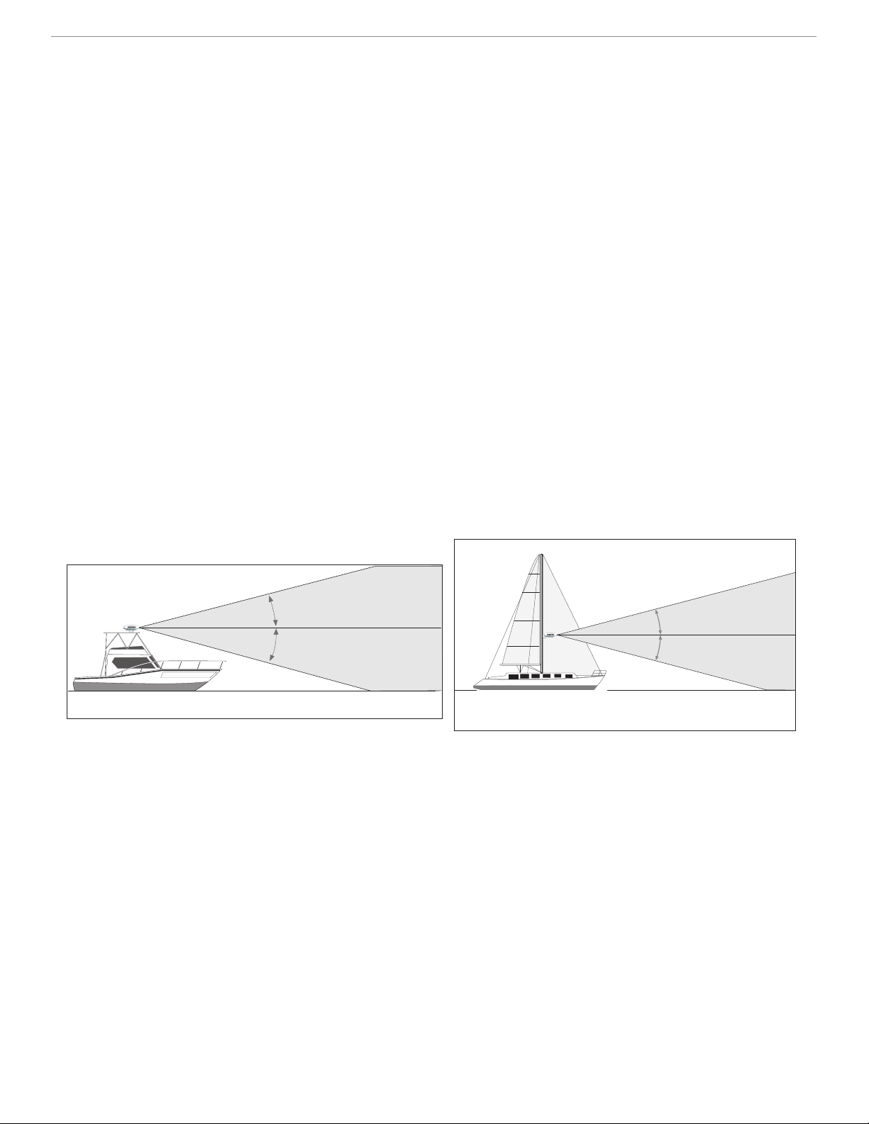
12.5°
12.5°
Ideal Radiation Plane
Ideal Radiation Plane
12.5°
12.5°
• Mount other electronics and cables more than 2 m (7 ft) from the path of a radar beam. A radar beam can normally be assumed to spread
25° vertically above and below the scanner’s radiating element. For vessel’s with higher bow angles at cruise speed, it may be helpful to
lower the angle so the beam points slightly downwards to the waterline while at rest. Shims may be used as necessary.
• Install the scanner away from antennas for other electronics. GPS antennas should be either above or below the radar beam path of the
scanner. Mount at least 1 m (3 ft) from any equipment transmitting or cables carrying radio signals e.g. VHF radios, cables and antennas.
In the case of SSB radios, the distance should be increased to 2 m (7 ft). IEC 60936-1 clause 3-27.1 maximum distances from the antenna
at which RF (Radio Frequency) levels can be expected.
GMR20 (100W/m squared = 40 cm [15.75"]) (10W/m squared = 120 cm [47.24"])
GMR40 (100W/m squared = 60 cm [23.62"]) (10W/m squared = 175 cm [68.90"])
• The radar scanner transmits electromagnetic energy. It is important that the radar is turned off or the DC power input is disconnected
whenever personnel are required to come close to the scanner to perform work on the scanner assembly or associated equipment.
Installation
The following order of mounting the scanner and attaching the Power/Network cables may vary depending on the installation location and
mount used.
2
GMR 20/40 Radar Installation Manual
Page 5
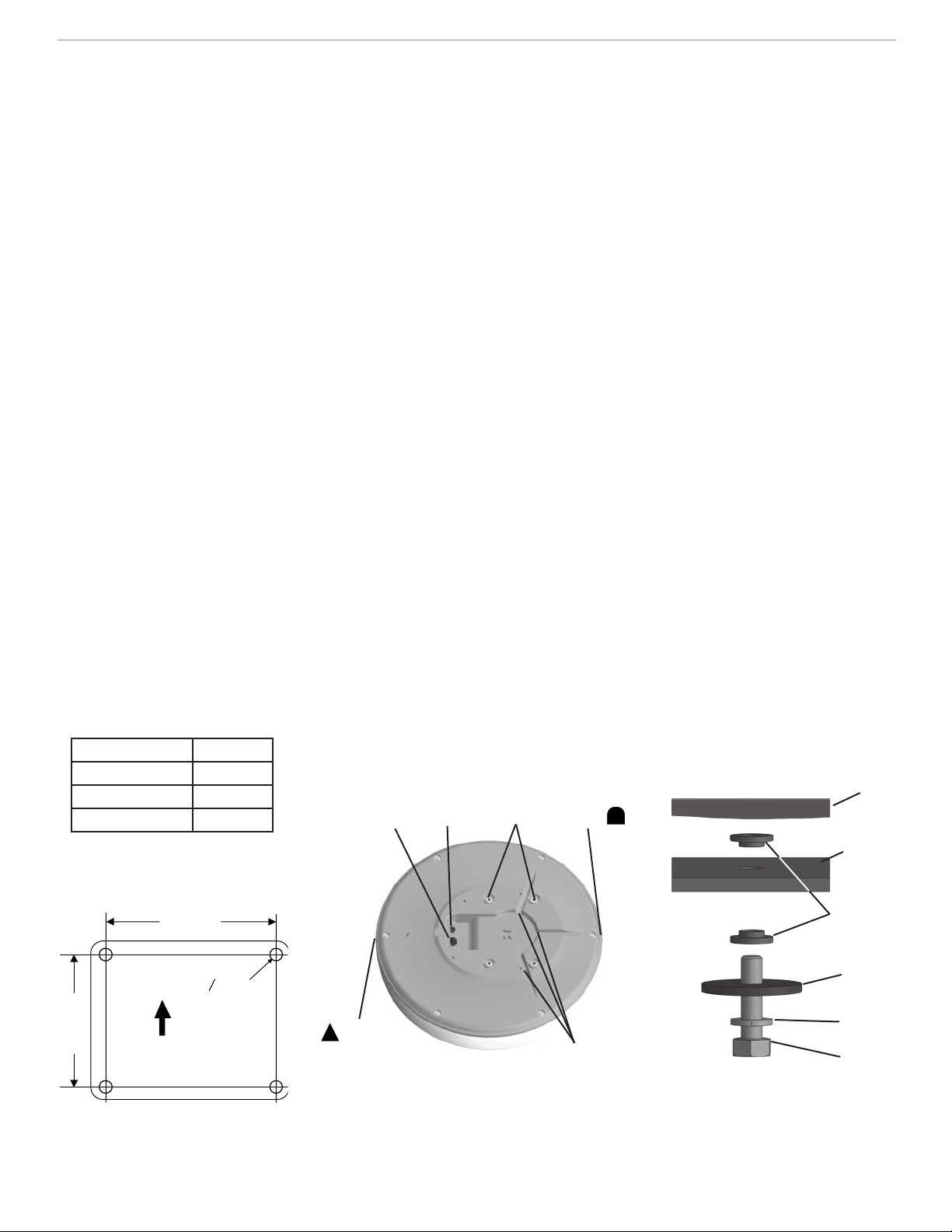
Mounting the Scanner
Ship's Bow
141.5 mm
(5.57")
233.0 mm
(9.17")
O 9.5 mm
(0.37")
1. Once a suitable mounting location has been determined, verify that the mounting hole locations are aligned fore and aft, then drill four
9.5 mm (0.37") mounting holes referencing Figure 1 below. (This step is not necessary if you are using a pre-drilled Garmin compatible
or Raymarine mount.)
2. Remove the supplied M8x30 bolts, flat washers, and spring washers (4 each) from the bottom of the scanner unit. Do NOT remove the
outer case bolts. There are no user serviceable parts in the scanner and opening the case may void your warranty.
3. Align the notch and locking ring on the Power Cable to the power connector. Press the 2-pin Power Cable to the power connector and
the RJ-45 Marine Network Cable to the RJ-45 socket (Figure 2). Turn the Power Cable locking ring clockwise until it stops. Tighten the
RJ-45 locking ring clockwise until it is firmly sealed.
4. The Power/Network Cable may be pressed into one of the three guide grooves moulded into the bottom of the scanner case (Figure 2).
Avoid excessive bending or twisting of the cable. See the following “Cable Runs” section for more information.
5. Position the scanner on the mounting surface with the triangular marks on the case aligned to the front of the vessel and the rounded
marks aligned towards aft (Figure 2). A bead of marine sealant may be applied around each of the mounting holes on the mounting
surface.
6. Fasten the scanner to the mounting surface using the M8x1.25x30 hex bolts, spring washers, and flat washer and shoulder washers
in the order show in Figure 3. The supplied M8x1.25x30 bolts, flat washers, and spring washers (4 each) may be used on mounting
thicknesses of 5-10 mm (3/8") (recommended). For surfaces over 10 mm (3/8"), locally supplied longer bolts are needed. The bolts
should be torqued to between 13.7-18.6 N m (10-14 lb ft).
Cable Runs
Route the cable as needed, depending on the type of mount you are using. Do NOT cut the cable! It may be necessary to drill a 31.7 mm
(1.25") hole for routing the Power/Network cable. Garmin provides a rubber Cable Grommet which may be used to cover the cable installation
hole. The grommet does NOT provide a waterproof seal. You may choose to apply a marine sealant after installation to weatherproof around the
grommet and cable. Additional Cable Grommets may be purchased through Garmin or your Garmin dealer.
When installing the Power/Network Cable, observe the following:
• To ensure safety, use the appropriate tie-wraps, fasteners, and sealant to secure the cable along a route and through any bulkhead or deck.
Avoid running the cable near moving objects, high heat sources, or through doorways and bilges.
• Avoid installing the cable next to or in parallel other cables such as, radio antenna lines or power cables. This is essential to avoid
interference to/from other equipment. If this is not possible, shield the cable with metal conduit or a form of EMI shielding.
• Install the Power portion of the cable as close to the battery source as possible. A minimum of 10 v D.C. is required at the 15 m cable
connector during radar turn-on and operation. See table below for recommended wire gauge between radar cable and battery.
Up to:
2 meters (6.5 ft) 16 AWG
4 meters (13 ft) 14 AWG
6 meters (19 ft) 12 AWG
Wire Gauge Table
Network
RJ-45 Port
Power
Connector
Mounting
Holes
Stern
Mark
Scanner
Mounting
Bracket
Shoulder
Washer
Flat
Washer
GMR 20/40 Radar Installation Instructions
Figure 1
Bow
Mark
Figure 2
Cable Guide
Grooves
Figure 3
Spring
M8x30
Bolt
3
Page 6

Final Wiring Connections
GPS 17
GARMIN
GPSMAP MFD
GMR 20/40 MARINE
RADAR
Once the scanner is installed and the cable routed, you are ready to connect the Power, Ground and Marine Network.
1. Connect the Black Ground (-) wire to the vessel’s negative power terminal.
2. Connect the Power (+) wire (with fuse holder) to the vessel’s positive power terminal.
3. For a stand-alone network (MFD and Radar only), attach the RJ-45 Marine Network Cable to the RJ-45 socket on the back of the MFD.
For an expanded network (MFD, Radar, GMS 10), attach the RJ-45 Marine Network Cable to an open RJ-45 socket on the GMS 10
Network Power Expander. Tighten the RJ-45 locking ring clockwise until it is firmly sealed.
Stand Alone Network
4
Expanded Network
GMR 20/40 Radar Installation Instructions
Page 7

Powering on the System
To power on the scanner:
1. On the MFD (Multi-Function Display), press the red Power key. The scanner is automatically powered on with the MFD. The Welcome
page appears showing the GMR 20 or GMR 40 as a detected Network Connection.
2. Press ENTER when I Agree turns yellow, then press PAGE until the Radar page appears.
3. During Standby mode, a countdown appears on the Radar page and the status bar as the scanner prepares to operate.
4. With the scanner “Ready”, press and hold the FCTN key until Do you want to begin radar transmission? appears.
5. When safe (personnel clear of radar beam path), highlight Yes and press ENTER. The scanner spins up and becomes operational.
Bearing Offset
It may be necessary to adjust the bearing of the radar picture shown on the screen. First, using a magnetic compass, take an optical bearing of a
stationary target located within viewable range. Measure the target bearing on the radar. If the bearing deviation is more than +/- 1°, then do the
following to correct for the offset:
1. From the Radar page, press the ADJ key to display the Adjustment Menu.
2. From the Adjustment Menu, select Setup and press ENTER.
3. Using the ROCKER key, highlight the Front of Boat Offset slider and press ENTER.
4. Press Left on the ROCKER key to adjust to a negative value or press Right to adjust to a positive value. The preview window below
changes as you adjust the slider.
5. Once an offset has been determined, press ENTER to save, then press QUIT to return to the Radar Page. Your new Garmin Marine
Radar is now ready to use! Refer to the GMR 20/40 Owner’s Manual for details on operating the scanner.
GMR 20/40 Radar Installation Instructions
5
Page 8

Specifications
Unit Dimensions: 28” (710 mm) D x 8” (205 mm) H
Radar Scanner Weight: Unit 26 lbs; cable 8.35 lbs
Range Scales (Range Rings): GMR 40 — 1/8 nm (1/32 nm) to 36 nm (9 nm)
GMR 20 — 1/8 nm (1/32 nm) to 24 nm (6 nm)
Power Output: GMR 20: 2 kW / GMR 40: 4 kW
Power Input Source: 10-35 v D.C. 28 W
Operating Temperature Range: -25° C to 70° C, and a relative humidity up to 95% at 35°C
Beamwidth: Horizontal beamwidth of 3.6° nominal / Vertical beamwidth of 25° nominal
Range: GMR 20: 24 nm / GMR 40: 36 nm
Wind Velocity: Wind speed up to 100 Kts
Antenna RPMs: 24 rpm
Range Ring Accuracy: +/- 1 meter
Bearing Accuracy: 1°
Minimum Range: 35 meters
Range Discrimination: 30 meters
Sensitivity and Tune Controls: Gain, Sea Clutter, Rain Clutter, and Frequency Tune
Radar/Chart Synchronization: Overlay mode. Split overlay with standard radar presentation.
Off Center Function: Look ahead, Auto Shift, and Manual
RF Transmit Frequency: 9410 ± 30 MHz
6
GMR 20/40 Radar Installation Instructions
Page 9

28"
(710.0 mm)
8"
(205.4 mm)
Towards Bow
Towards Stern
9.17"
(233.0 mm)
13.97"
(355.0 mm)
GMR 20/40 Radar Installation Instructions
5.57"
(141.5 mm)
8.40"
(213.5 mm)
7
Page 10

I
Warning and Cautions
CAUTION: Use the GMR 20/40 at your own risk. To reduce the risk of unsafe operation, carefully review and understand all aspects of
this Owner’s Manual, and thoroughly practice operation using the simulator mode prior to actual use. When in actual use, carefully compare
indications from the GMR 20/40 to all available navigation sources, including the information from other NAVAIDs, visual sightings, charts,
etc. For safety, always resolve any discrepancies before continuing navigation.
CAUTION: IT IS THE USER’S RESPONSIBILITY TO USE THIS PRODUCT PRUDENTLY. THIS PRODUCT IS INTENDED TO BE
USED ONLY AS A NAVIGATIONAL AID AND MUST NOT BE USED FOR ANY PURPOSE REQUIRING PRECISE MEASUREMENT
OF DIRECTION, DISTANCE, LOCATION, OR TOPOGRAPHY.
WARNING: This product, its packaging, and its components contain chemicals known to the State of California to cause cancer, birth defects,
or reproductive harm. This Notice is being provided in accordance with California’s Proposition 65. If you have any questions or would like
additional information, please refer to our web site at http://www.garmin.com/prop65.
WARNING: The radar scanner transmits electromagnetic energy. Ensure that the scanner has been installed according to the recommendations
given in this guide, and that all personnel are clear of the scanner, before switching to transmit mode.
FCC Compliance
The GMR 20/40 complies with Part 80 of the FCC rules. It has received a grant of equipment authorization, issued under the authority of the FCC.
This equipment generates, uses and can radiate radio frequency energy and, if not installed and used in accordance with the instructions, may
cause harmful interference to radio communications. However, there is no guarantee that interference will not occur in a particular installation.
If this equipment does cause harmful interference to radio or television reception, which can be determined by turning the equipment off and
on, the user is encouraged to try to correct the interference by one of the following measures:
• Reorient or relocate the receiving antenna.
• Increase the separation between the equipment and the receiver.
• Connect the equipment into an outlet on a circuit different from that to which the receiver is connected.
• Consult the dealer or an experienced radio/TV technician for help.
8
GMR 20/40 Radar Installation Instructions
Page 11

Software License Agreement
BY USING THE GMR 20/40, YOU AGREE TO BE BOUND BY THE TERMS AND CONDITIONS OF THE FOLLOWING SOFTWARE
LICENSE AGREEMENT. PLEASE READ THIS AGREEMENT CAREFULLY.
Garmin grants you a limited license to use the software embedded in this device (the “Software”) in binary executable form in the normal
operation of the product. Title, ownership rights and intellectual property rights in and to the Software remain in Garmin.
You acknowledge that the Software is the property of Garmin and is protected under the United States of America copyright laws and
international copyright treaties. You further acknowledge that the structure, organization and code of the Software are valuable trade secrets of
Garmin and that the Software in source code form remains a valuable trade secret of Garmin. You agree not to decompile, disassemble, modify,
reverse assemble, reverse engineer, or reduce to human readable form the Software or any part thereof or create any derivative works based on
the Software. You agree not to export or re-export the Software to any country in violation of the export control laws of the United States of
America.
Limited Warranty
This Garmin product is warranted to be free from defects in materials or workmanship for one year from the date of purchase. Within this
period, Garmin will at its sole option repair or replace any components that fail in normal use. Such repairs or replacement will be made at no
charge to the customer for parts or labor, provided that the customer shall be responsible for any transportation cost. This warranty does not
cover failures due to abuse, misuse, accident or unauthorized alteration or repairs.
THE WARRANTIES AND REMEDIES CONTAINED HEREIN ARE EXCLUSIVE AND IN LIEU OF ALL OTHER WARRANTIES
EXPRESS OR IMPLIED OR STATUTORY, INCLUDING ANY LIABILITY ARISING UNDER ANY WARRANTY OF
MERCHANTABILITY OR FITNESS FOR A PARTICULAR PURPOSE, STATUTORY OR OTHERWISE. THIS WARRANTY GIVES YOU
SPECIFIC LEGAL RIGHTS, WHICH MAY VARY FROM STATE TO STATE.
IN NO EVENT SHALL GARMIN BE LIABLE FOR ANY INCIDENTAL, SPECIAL, INDIRECT OR CONSEQUENTIAL DAMAGES,
WHETHER RESULTING FROM THE USE, MISUSE, OR INABILITY TO USE THIS PRODUCT OR FROM DEFECTS IN THE
PRODUCT. Some states do not allow the exclusion of incidental or consequential damages, so the above limitations may not apply to you.
Garmin retains the exclusive right to repair or replace the unit or software or offer a full refund of the purchase price at its sole discretion.
SUCH REMEDY SHALL BE YOUR SOLE AND EXCLUSIVE REMEDY FOR ANY BREACH OF WARRANTY.
To obtain warranty service, contact your local Garmin authorized dealer or call Garmin Product Support for shipping instructions and an RMA
tracking number. The unit should be securely packed with the tracking number clearly written on the outside of the package. The unit should
then be sent, freight charges prepaid, to any Garmin warranty service station. A copy of the original sales receipt is required as the proof of
purchase for warranty repairs.
Garmin International, Inc.
1200 E 151st Street, Olathe, Kansas 66062 U.S.A.
Tel. 913/397.8200
Fax. 913/397.8282
Garmin (Europe) Ltd.
Unit 5, The Quadrangle, Abbey Park Industrial Estate, Romsey, SO51 9DL U.K.
Tel. 44/0870.8501241
Fax 44/0870.8501251
Online Auction Purchases: Products sold through online auctions are not eligible for rebates or other special offers from Garmin. Online
auction confirmations are not accepted for warranty verification. To obtain warranty service, an original or copy of the sales receipt from the
original retailer is required. Garmin will not replace missing components from any package purchased through an online auction.
International Purchases: A separate warranty is provided by international distributors for units purchased outside the United States. This
warranty is provided by the local in-country distributor and this distributor provides local service for your unit. Distributor warranties are only
valid in the area of intended distribution. Units purchased in the United States or Canada must be returned to the Garmin service center in the
United Kingdom, the United States, Canada, or Taiwan for service.
The Garmin GMR 20/40 has no user-serviceable parts. Should you ever encounter a problem with your unit, please take it to an authorized
Garmin dealer for repairs.
The GMR 20/40 is fastened shut with screws. Any attempt to open the case to change or modify the unit in any way will void your warranty
and may result in permanent damage to the equipment.
GMR 20/40 Radar Installation Instructions
9
Page 12

Issued: 19/04/2004
Revised: 24/08/2005
Page:
1 of 1
DECLARATION of CONFORMITY
Application of Council Directive: 1999/5/EC
Standard t
o which Conformity is Declared: IEC 60945 Marine Navigational Equipment – General
Requirements
IEC 62252 Maritime Navigation and Radiocommunication
Equipment and System
s
EN 6
0936-1 Maritime Navigation and Radiocommunication
Equipment and System
s
ITU-SM
.1541 Unwanted Emissions in the Out-of-Band
Dom
ain
ITU-R
M.1177 Unwanted Emissions – Techniques for
Measure
ment
Not
ified Body number: 0191
Manufactured by: GARMIN International & GARMIN Corporation
Manufacture’s Address: 1200 E. 151
st
Street No.68, Jangshu 2ndRd.,
Olathe, Kansas 66062 Shijr, Taipei County,
U.S.A TAIWAN, R.O.C.
Authorised Representative: GARMIN (Europe) Ltd, The Quadrangle,
Abbey Park Ind. E
state, Romsey, Hampshire,
SO
51 9DL, U.K.
Type of Equipment: Marine Radar
Model Number(s): GMR 20
GMR 40
The undersi
gned does hereby declare that the equipment complies to the above Directives
Paul M
orrow
Quality Man
ager
GAR
MIN (Europe) Ltd Date: 24
th
August 2005
10
GMR 20/40 Radar Installation Instructions
Page 13

Page 14

© Copyright 2004, 2005 Garmin Ltd. or its subsidiaries
Garmin International, Inc.
1200 E 151st Street, Olathe, Kansas 66062 U.S.A.
Tel. 913/397.8200
Fax. 913/397.8282
Garmin (Europe) Ltd.
Unit 5, The Quadrangle, Abbey Park Industrial Estate, Romsey, SO51 9AQ U.K.
Tel. 44/0870.8501241
Fax. 44/0870.8501251
Garmin Corporation
No. 68, Jangshu 2nd Road, Shijr, Taipei County, Taiwan
Tel. 886/2.2642.9199
Fax. 886/2.2642.9099
Part Number 190-00457-02 Rev. C
 Loading...