

Page 1

GMI™ 10
quick start manual
Page 2
Introduction
See the Important Safety and Product Information guide in the product box for
product warnings and other important information.
The GMI™ 10 allows you to quickly view important information about your
boat provided by connected sensors. Connected sensors transmit data to the
GMI 10 using NMEA 2000® or NMEA 0183. To install your GMI 10, use the
included installation instructions.
For a list of compatible sensors and for more information
about NMEA 2000, visit www.garmin.com. The GMI 10
is NMEA 2000 certied.
Manual Conventions
In this manual, when you are instructed to select an item, use the soft keys
( ) along the bottom of the screen to select each item. Small arrows (>)
in the text indicate that you should select each item in order.
Instrument Screen—the instrument screen displays data provided by a
sensor.
Menu Screens—screens used to dene options.
2 GMI 10 Quick Start Manual
Page 3

Unit Overview
Instrument screen
Back
Soft keys
Power
Power—press and hold to power the unit on and off. Press and quickly
release to adjust display settings.
Soft Keys—used to navigate the menus and select items on the GMI 10.
Typically, the left and right soft keys cycle data on the instrument screen and
navigate menu screens, and the center soft key selects highlighted items and
opens the Menu.
Back—used to move back one menu screen. Press and hold to move all the
way back to the instrument screen from any menu screen.
GMI 10 Quick Start Manual 3
Page 4

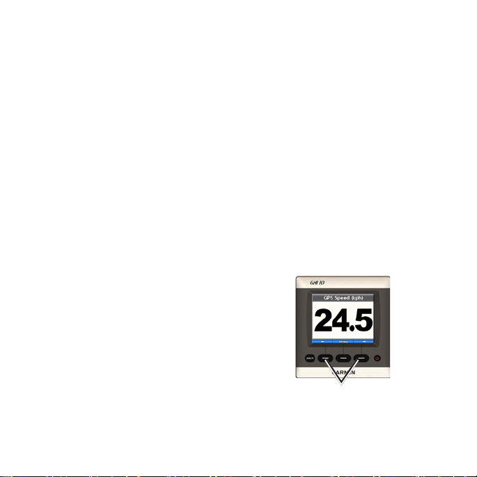
Using the GMI 10
Use the GMI 10 to view numerical
data provided by connected sensors.
Many data types can also be
displayed as an analog gauge.
The types of data available
are determined by the sensors
connected to the GMI 10 either
through NMEA 2000 or
NMEA 0183.
For example, when connected to a
GPS antenna such as a GPS 17x,
the GMI 10 can show GPS
position, GPS heading (COG),
GPS speed (SOG), average speed,
maximum speed obtained, and
distance traveled (trip odometer)
information.
4 GMI 10 Quick Start Manual
Viewing Information
Instrument screens are organized
by category. Categories match the
data available on an instrument,
such as depth instruments. You can
congure the GMI 10 to mix data
from common instruments to make
a custom instrument tailored to the
sensors on your boat.
Each category can contain a variety
of screens that you can quickly
cycle through.
Selecting an Instrument
Screen Category
Change the instrument screen to a
different category from the menu:
1. From the instrument screen,
select Menu > Setup > Set
Instrument Type.
Page 5
2. Choose from the categories
listed below.
Surface—GPS or water
•
speed, GPS heading or
magnetic sensor heading,
and odometer.
Water—depth and water
•
temperature.
Fuel—level, rate, range, and
•
economy.
Wind—wind speed and
•
angle, ground wind speed
and direction, wind velocity
made good (VMG), race
timer, wind and weather
graphs, barometric pressure,
and air temperature.
Engine—RPM, fuel
•
ow, trim, temperature,
pressure, voltage, hours,
neutral indicator, and status
indicators.
GMI 10 Quick Start Manual 5
Custom—arrange a custom
•
set of instruments. Utilize an
existing instrument or graph,
or create a custom instrument
screen.
Cycling Through
Instrument Screens in a
Category
When viewing a category, use the
soft keys under the left and right
arrows to cycle through the screens
available in that category.
Cycle through instrument screens
Page 6

Changing Instrument
Screen Options
Data provided on an instrument
screen is represented numerically. In
many cases, a numerical value can
be shown as an analog gauge or as a
graph, and vice versa (not available
on all instrument screens).
To change the appearance of
an instrument screen:
If the instrument screen is
•
showing a number, select
Menu > Show Gauge or
Show Graph.
If the instrument screen
•
is showing a gauge or a
graph, select Menu > Show
Number.
6 GMI 10 Quick Start Manual
To change additional options
on an instrument screen:
1. From the instrument screen,
select Menu.
2. To change the source sensor,
select Source, and choose the
sensor you want to use. For
example, if you have a GPS
antenna and a heading sensor,
you can choose to show either
GPS Heading (COG) or Heading
from the heading sensor.
3. To change additional options,
such as resetting an odometer,
adding Trip Speed Graphics to a
speed gauge, viewing a watertemperature graph, or adding
fuel, select the option you want
to change.
Page 7

Understanding Custom
Instrument Screens
You can create up to ten of the
following kinds of customized
displays on the GMI 10:
You can organize individual
•
screens found in the predened
categories (for multiple
instruments) to create your own
customized collection of screens.
You can select the individual
•
elds to show on each screen to
create customized screens.
To create a customized
combination of individual
instrument screens found in
the predened categories:
1. Select Menu > Setup > Set
Instrument Type > Custom.
GMI 10 Quick Start Manual 7
2. Use the soft keys under the left
and right arrows to cycle through
the instrument screens available
in the selected category.
3. Select Select to add a screen.
To create the rst custom
instrument screen:
1. From the instrument screen,
select Menu > Setup > Set
Instrument Type > Custom >
Custom Page.
2. Select the number of elds you
want to show on the custom
instrument screen (1–4).
3. Select the data type you would
like to show in each eld.
Page 8

To add additional custom
instrument screens:
1. From the custom instrument
screen, select Menu > Add
Page > Custom Page. (If you
have more than one custom
instrument screen, this option
will appear as Add/Remove
Page.)
2. Select the number of elds you
want to show on the custom
instrument screen (1–4).
Select the data for each eld
To add graph screens to your
customized combination of
existing instrument screens:
1. Select Menu > Setup > Set
Instrument Type > Custom >
Graphs.
2. Select Select to add a screen.
To customize graph screens:
1. When viewing the graph screen,
select Menu.
Select the number of elds
3. Select the data type you would
like to show in each eld.
8 GMI 10 Quick Start Manual
2. Select Graph Data, Graph
Duration, or Graph Scale to
adjust the appearance of the
graph screen.
Page 9

3. Select the data type you would
like to show in each eld.
NOTE: You can create up to ten
custom instrument screens and
cycle through them.
To change a previously createdchange a previously created
custom instrument screen:
To remove a previously created
custom instrument screen:
1. Navigate to the custom
instrument screen you want to
remove.
2. Select Menu > Add/Remove
Page > Remove Page.
1. From the custom instrument
screen you want to change,
select Menu > Change
Appearance.
2. Choose from the following
options:
Select Change Page Layout
•
to change the number of
elds and data types in the
elds.
Select Change Data Style
•
to switch between numerical
and analog displays.
3. Select Done when nished.
GMI 10 Quick Start Manual 9
Page 10

Customizing SystemSystem
Options
TIP: You must have the appropriate
sensors connected to view the
information.
1. To customize system options on
the GMI 10, from the instrument
screen, select Menu > Setup >
System.
2. For the listed options, select the
appropriate settings or enter the
necessary values. For example,
you can select units of measure,
language, enter total fuel
capacity, and so on.
To set the reference used to
calculate heading information:
1. From the instrument screen,
select Menu > Setup > System
> Heading.
10 GMI 10 Quick Start Manual
2. Choose from the following
options:
Auto Magnetic—Automatic
•
Magnetic Variation
automatically sets the
magnetic declination for your
acquired GPS position.
True—sets true north as the
•
heading reference.
User Magnetic—allows you
•
to set the magnetic variation
value.
To congure the audible
beeper:
1. From the instrument screen,
select Menu > Setup > System
> Beeper.
2. Select from the following options
to determine when the GMI 10
makes audible sounds: Off,
Alarms Only, On (Keys &
Alarms).
Page 11

To specify how the GMI 10
utilizes coordinates:
CAUTION: Do not change the
position format or map datum
unless you are using a map or
chart that species a different
position format or map datum.
1. From the instrument screen,
select Menu > Setup > System
> Position.
2. Choose from the following
options:
Position Format—change
•
the coordinate style in which
a given location reading
appears.
Map Datum—change the
•
To specify the speed sensor
used when performing fuel
economy calculations:
1. From the instrument screen,
select Menu > Setup > System
> Speed Sources.
2. Select Fuel Economy.
3. Select the appropriate sensor.
To specify the speed sensor
used when performing wind
calculations:
1. From the instrument screen,
select Menu > Setup > System
> Speed Sources.
2. Select Wind.
3. Select the appropriate sensor.
coordinate system on which
the position format is based.
GMI 10 Quick Start Manual 11
Page 12

Low Fuel—set an alarm
Setting Alarms
1. To set alarms on the GMI 10,
from the instrument screen,
select Menu > Setup > Alarms.
2. Select from the following alarm
types. Select On and enter an
appropriate value.
Shallow Water—set an
•
alarm to sound when the
depth is less than the
specied value.
Deep Water—set an alarm
•
to sound when the depth is
greater than the specied
value.
Surface Temperature—set
•
an alarm to sound when
the transducer reports a
temperature that is 2°F
(1.1°C) above or below the
specied temperature.
12 GMI 10 Quick Start Manual
•
to sound when the fuel
remaining (based on fuel-ow
information from a GFS 10)
reaches the specied level.
Engine Status—set an alarm
•
to sound when an engine
indicates there is a problem.
Low Apparent Wind
•
Speed—set an alarm to
sound when the apparent
wind speed is at or below the
specied speed.
High Apparent Wind
•
Speed—set an alarm to
sound when the apparent
wind speed is at or above the
specied speed.
Low True Wind Speed—set
•
an alarm to sound when the
true wind speed is at or below
the specied speed.
Page 13

High True Wind Speed—set
•
an alarm to sound when
the true wind speed is at or
above the specied speed.
High Apparent Wind
•
Angle—set an alarm to
sound when the apparent
wind angle is at or above the
specied angle.
Low Apparent Wind
•
Angle—set an alarm to
sound when the apparent
wind angle is at or above the
specied angle.
Low True Wind Angle—set
•
an alarm to sound when the
true wind angle is at or below
the specied angle.
High True Wind Angle—set
•
an alarm to sound when the
true wind angle is at or above
the specied angle.
GMI 10 Quick Start Manual 13
Battery Voltage—set an
•
alarm to sound when the
battery voltage reaches the
specied level.
Changing the DisplayDisplay
Options
1. To change the display options on
the GMI 10, from the instrument
screen select Menu > Setup >
Display.
2. Select a value for the listed
options.
TIP: You can also access
the display options menu by
pressing and quickly releasing
the POWER button from any
instrument screen.
Page 14

Changing NMEA 2000 Device Options
You can view information about
your NMEA 2000 devices and
change available device-specic
options on the GMI 10.
1. From the instrument screen,
select Menu > Setup > NMEA
2000 Devices.
2. You will see a list of all
connected NMEA 2000
devices. Select a device to see
information about the device,
such as the software version and
the serial number.
Advanced Sensor
Conguration
1. From the instrument screen,
select Menu > Setup > NMEA
2000 Devices.
2. Select the appropriate sensor.
Select Cong.
3. Enter the appropriate values for
the listed options.
TIP: For more information on
conguring the sensor, refer to
the installation instructions for
the sensor.
Honda Engine ECO Symbol
The symbol appears when
boats with NMEA 2000-compatible
Honda engines are running in a
fuel-efcient mode and engine RPM
is displayed.
14 GMI 10 Quick Start Manual
Page 15

Consult your Honda engine manual
to determine if the engine is NMEA
2000 compatible.
Lost Satellite Reception—a
connected GPS antenna has lost
satellite reception.
System Alarms and Messages
NOTE: There are several possible
engine alarms. If the GMI 10
displays an engine alarm, contact
your engine manufacturer.
Boat Is Not Moving Fast Enough
to Calibrate—water speed
calibration – the boat is moving too
slow to calibrate.
Connection with NMEA 2000
Device Lost—the GMI 10 has lost
connection with a NMEA 2000
device.
GMI 10 Quick Start Manual 15
NMEA Depth Is Below
Transducer—the NMEA depth
input is using the DBT sentence
which does not include keel offset.
NMEA 2000 Device Requires
Calibration—a NMEA 2000
device requiring calibration has
been detected.
Simulating Operation
is in demo mode. Do not drive or
operate the boat while the GPS
device is in Demo mode. To change
the operating mode, select Menu
> Setup > System > Operating
Mode > Normal.
—the unit
Page 16

Unable to Claim NMEA 2000
Address—there is a conict
between NMEA 2000 devices on
the NMEA 2000 network.
Water Speed Sensor Is Not
Working—water speed calibration
error – recalibrate the speed sensor.
16 GMI 10 Quick Start Manual
Contact Garmin
Contact Garmin Product Support
if you have any questions while
using your GMI 10. In the USA,
go to www.garmin.com/support, or
contact Garmin USA by phone at
(913) 397-8200 or (800) 800-1020.
In the UK, contact Garmin (Europe)
Ltd. by phone at 0808 2380000.
In Europe, go to www.garmin.com/
support and click Contact Support
for in-country support information,
or contact Garmin (Europe) Ltd. by
phone at +44 (0) 870.8501241.
Page 17

Page 18

Page 19

Page 20

© 2009 Garmin Ltd. or its subsidiaries
Garmin International, Inc.
1200 East 151st Street, Olathe, Kansas 66062, USA
Garmin (Europe) Ltd.
Liberty House, Hounsdown Business Park, Southampton, Hampshire,
SO40 9LR UK
Garmin Corporation
No. 68, Jangshu 2nd Road, Shijr, Taipei County, Taiwan
www.garmin.com
October 2009 Part Number 190-01015-01 Rev. C Printed in Taiwan
 Loading...