

Page 1
SPECIFICATION
REVISIONS
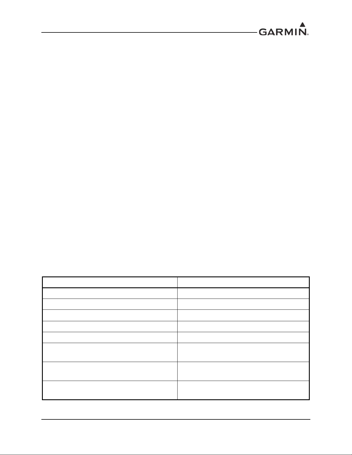
REV. DATE DESCRIPTION ECO NO.
CONTROL
DRAWING
NOTES:
1. DESCRIPTION: Installation Documentation
2. DISTRIBUTION: This document is intended for electronic distribution.
F 9/2/15 Added the GMA 35c 132290
G 10/2/15 Included FCC commetnts 133098
H 3/22/16 Added European Union and Brazil statements 139773
The following les have been archived under the above ARCHIVE FILENAME.
Filename File Contents
Portable Document Format, contains Installation Manual and Release Specication
190-00858-11.pdf
release.indd Adobe InDesign Format, Release Specication
Manual Elements FrameMaker, Formatted Files and Figures
*.* Various supporting illustrations, drawings, and artwork.
CONFIDENTIAL
This drawing and the specications contained herein are the property of Garmin
Ltd. or its subsidiaries and may not be reproduced or used in whole or in part as
the basis for manufacture or sale of products without written permission .
Date:
Drafter:
JGS
1/20/11
TITLE:
SIZE
A
Scale:
GMA 35 Installation Manual
PART NO:
190-00858-11
N/A
Garmin Ltd. or its subsidiaries
c/o Garmin International, Inc.
1200 E. 151st Street
Olathe, Kansas 66062 U.S.A.
Sheet of
REV.
H
1 1
Page 2

GMA 35/35c
Installation Manual
190-00858-11 March, 2016 Revision H
Page 3

© 2016
Garmin Ltd. or its subsidiaries
All Rights Reserved
Except as expressly provided herein, no part of this manual may be reproduced, copied, transmitted, disseminated, downloaded or stored in any storage medium, for any purpose without the express prior written
consent of Garmin. Garmin hereby grants permission to download a single copy of this manual and of any
revision to this manual onto a hard drive or other electronic storage medium to be viewed and to print one
copy of this manual or of any revision hereto, provided that such electronic or printed copy of this man ual
or revision must contain the complete text of this copyright notice and provided further that any unauthorized commercial distribution of this manual or any revision hereto is strictly prohibited.
©2015 The Bluetooth
®
word mark and logos are registered trademarks owned by Bluetooth SIG, Inc. and
any use of such marks by Garmin is under license. Other trademarks and trade names are those of their
respective owners.
Garmin International, Inc.
1200 E. 151st Street
Olathe, KS 66062 USA
Telephone: 913-397-8200
Aircraft On Ground (AOG) Hotline: (913) 397-0836
Aviation Dealer Technical Support Line (Toll Free): (888) 606-5482
www.garmin.com
Garmin (Europe) Ltd
Liberty House, Hounsdown Business Park
Southampton, Hampshire SO40 9LR U.K.
Phone: +44 (0) 23 8052 4000
Fax: +44 (0) 23 8052 4004
Aviation Support +44 (0) 37 0850 1243
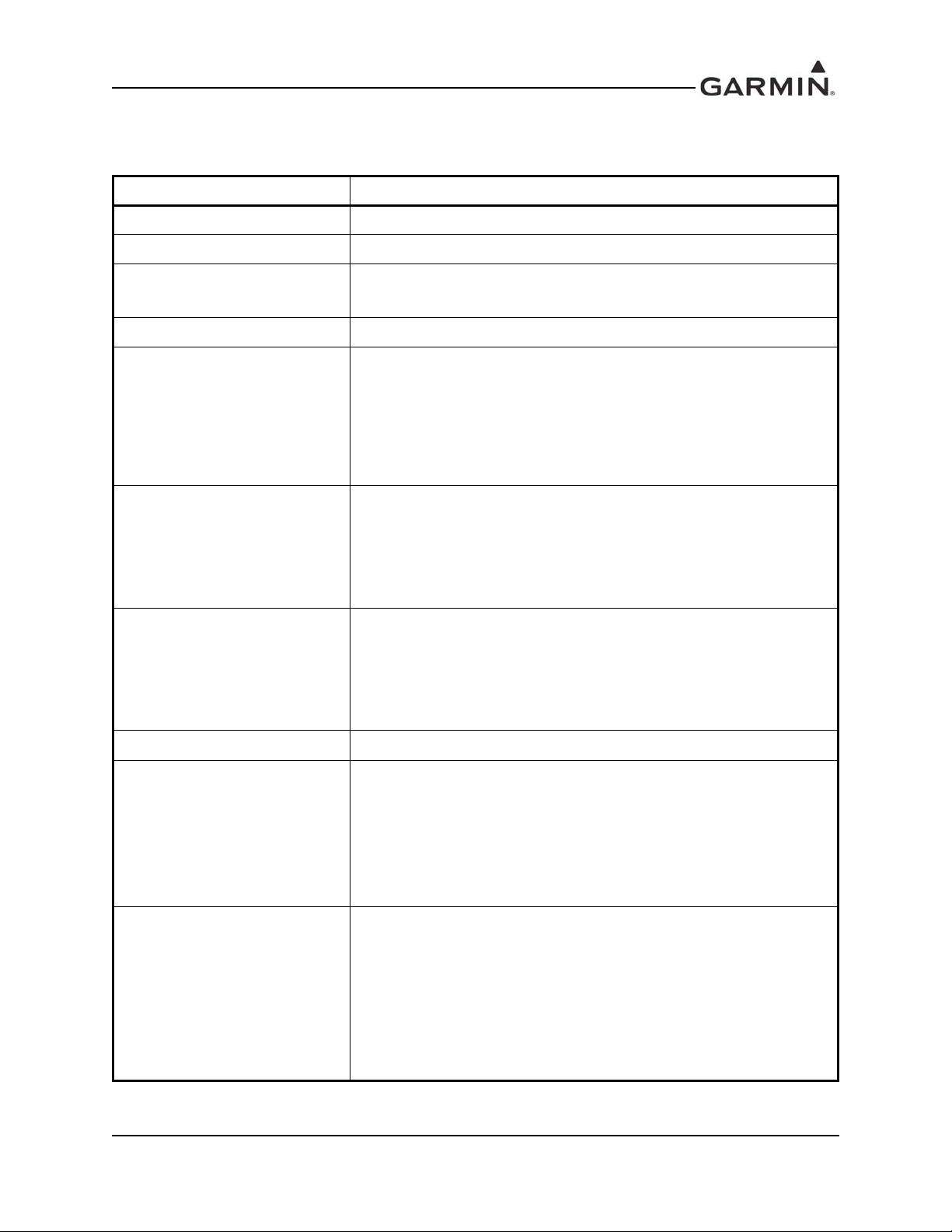
RECORD OF REVISIONS
Revision
Revision
Date
Description
A 1/20/11 Production Release
B 5/10/11 Added new mechanical drawing
C 12/27/11 Added ETSO-2C35d and ETSO-C139
D 2/27/12 Corrected copilot headset pinout
E 3/9/15 Added software part numbers
F 9/2/15 Added the GMA 35c
G 10/2/15 Included FCC comments
H 3/22/16 Added European Union and Brazil statements
Page A GMA 35/35c Installation Manual
Revision H 190-00858-11
Page 4
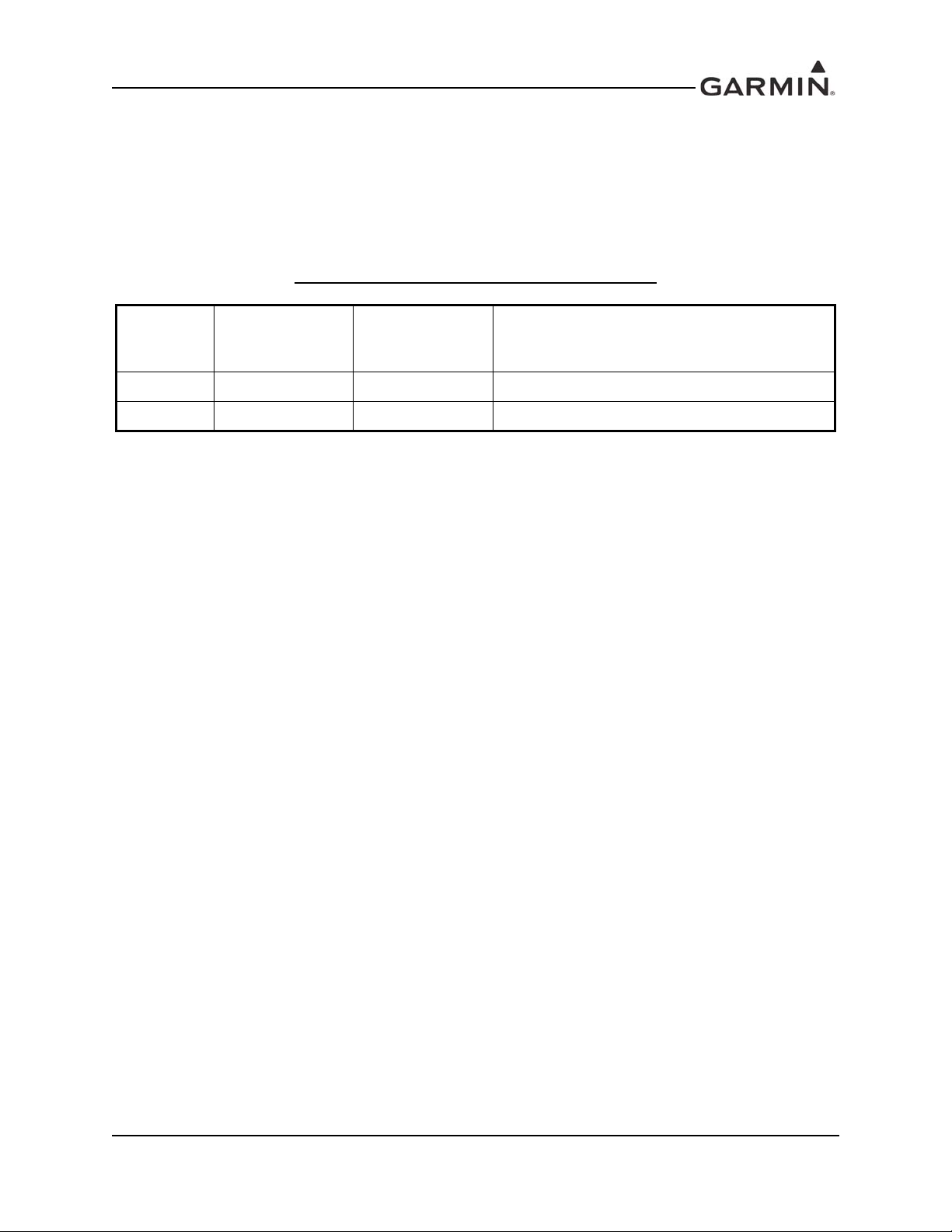
CURRENT REVISION DESCRIPTION
Revision
H
Page
Number(s)
ii TOC Added Declaration of Conformity
1-5 1.4.1
4-5 4.4 Corrected I/O designation
4-7
C-1 C Added breaker current rating guidance
C-3 C Added breaker note
Section
Number
4.5.4
4.5.5
Description of Change
Clarified TSO table and added boot block part
numbers
Corrected pin names
190-00858-11 GMA 35/35c Installation Manual
Rev. H Page i
Page 5
INFORMATION SUBJECT TO EXPORT CONTROL LAWS
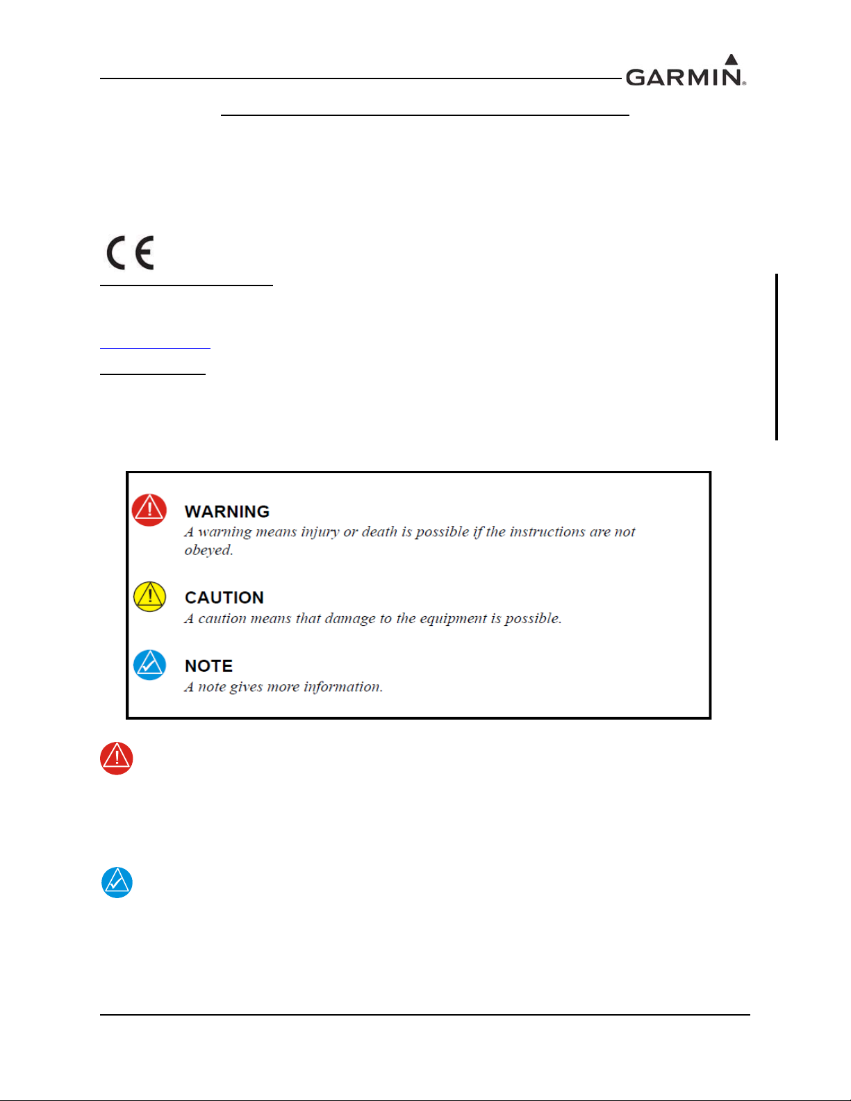
WARNING
NOTE
This document may contain information which is subject to the Export Administration Regulations
(“EAR”) issued by the United States Department of Commerce (15 CFR, Chapter VII Subchapter C) and
which may not be exported, released or disclosed to foreign nationals inside or outside the United States
without first obtaining an export license. The preceding statement is required to be included on any and all
reproductions in whole or in part of this manual.
Declaration of Conformity
Hereby, Garmin declares that this product is in compliance with the essential requirements and other
relevant provisions of Directive 1999/5/EC. To view the full Declaration of Conformity, go to
www.garmin.com
Anatel Warning
Este equipamento opera em caráter secundário, isto é, não tem direito a proteção contra interferência
prejudicial, mesmo de estações do mesmo tipo, e não pode causar interferência a sistemas operando em
caráter primário.
.
DEFINITIONS OF WARNINGS, CAUTIONS, AND NOTES
Limited Warranty
garmin.com/aviationwarranty
190-00858-11 GMA 35/35c Installation Manual
Rev. H Page ii
This product, its packaging, and its components contain chemicals known to the State of
California to cause cancer, birth defects, or reproductive harm. This Notice is being
provided in accordance with California's Proposition 65. If you have any questions or
would like additional information, please refer to our web site at www.garmin.com/prop65.
Throughout this document references made to the GMA 35 shall equally apply to the
GMA 35c except where specifically noted.
Page 6

1 GENERAL DESCRIPTION ...........................................................................1-1
1.1 Introduction ..................................................................................................................... 1-1
1.2 Equipment Description.................................................................................................... 1-1
1.3 Technical Specifications.................................................................................................. 1-2
1.4 Certification.....................................................................................................................1-5
1.5 Reference Documents...................................................................................................... 1-6
1.6 Operating Instructions .....................................................................................................1-7
2 INSTALLATION OVERVIEW......................................................................2-1
2.1 Introduction ..................................................................................................................... 2-1
2.2 Installation Materials....................................................................................................... 2-1
2.3 Installation Considerations.............................................................................................. 2-2
2.4 Cabling & Wiring...........................................................................................................2-4
2.5 Cooling Air......................................................................................................................2-4
2.6 Mounting Requirements.................................................................................................. 2-5
2.7 Installation Approval Considerations for Pressurized Aircraft .......................................2-6
2.8 Electrical Noise................................................................................................................ 2-6
3 INSTALLATION PROCEDURE...................................................................3-1
3.1 Unpacking Unit................................................................................................................ 3-1
3.2 Antenna Installation......................................................................................................... 3-1
3.3 Antenna Cable Connectors.............................................................................................. 3-1
3.4 Electrical Connections..................................................................................................... 3-1
3.5 Backshell Assembly ........................................................................................................ 3-2
3.6 GMA 35 Unit Installation................................................................................................ 3-3
3.7 Post Installation Configuration & Checkout ................................................................... 3-4
3.8 Continued Airworthiness................................................................................................. 3-6
4 SYSTEM INTERCONNECTS........................................................................4-1
4.1 Pin List............................................................................................................................. 4-1
4.2 Power...............................................................................................................................4-5
4.3 Serial Data .......................................................................................................................4-5
4.4 Lighting ........................................................................................................................... 4-5
4.5 Audio Inputs and Outputs................................................................................................ 4-6
4.6 Music Inputs .................................................................................................................. 4-10
4.7 Mic Keys........................................................................................................................ 4-10
4.8 Marker Beacon ..............................................................................................................4-11
4.9 Miscellaneous Configurable I/O.................................................................................... 4-12
190-00858-11 GMA 35/35c Installation Manual
Rev. H Page iii
Page 7

Appendix A INSTALLATION CONSIDERATIONS FOR UPGRADING
FROM A GARMIN GMA 340...........................................................................A-1
A.1 Mechanical Considerations............................................................................................ A-1
A.2 Electrical Considerations............................................................................................... A-1
Appendix B OUTLINE AND INSTALLATION DRAWINGS .....................B-1
Appendix C INTERCONNECT DRAWINGS ................................................C-1
190-00858-11 GMA 35/35c Installation Manual
Rev. H Page iv
Page 8
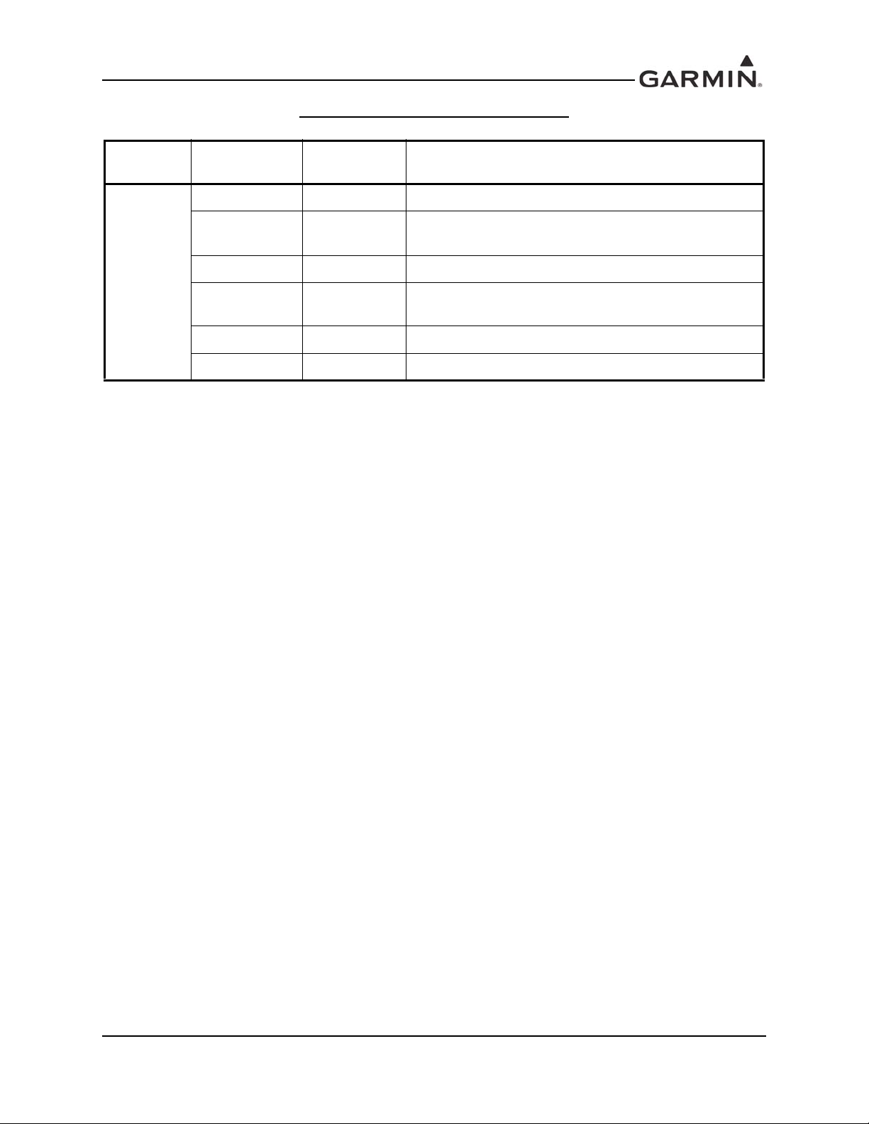
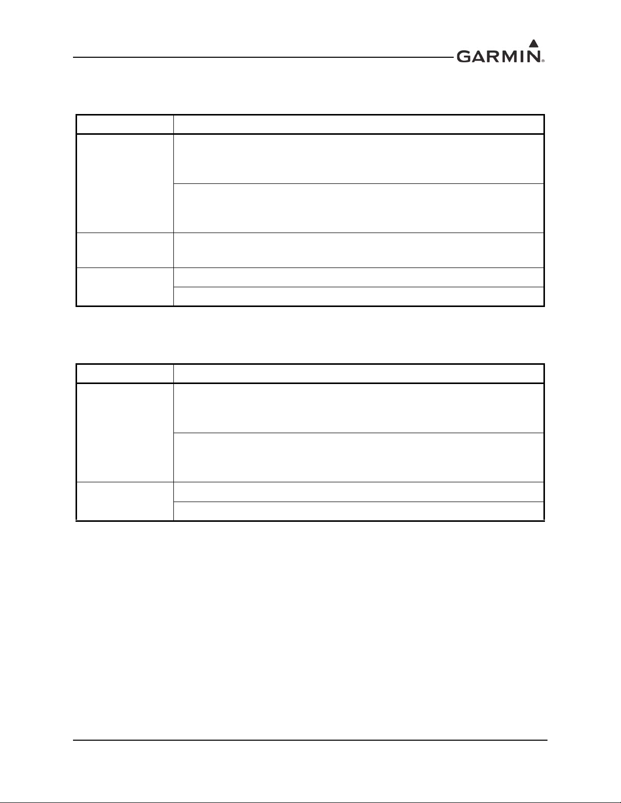
The following table identifies hardware modification (Mod) Levels for the GMA 35. Mod Levels
are listed with the associated service bulletin number, service bulletin date, and the purpose of the
modification. The table is current at the time of publication of this manual (see date on front cover) and is
subject to change without notice. Authorized Garmin Sales and Service Centers are encouraged to access
the most up-to-date bulletin and advisory information on the Garmin Dealer Resource web site at
www.garmin.com using their Garmin-provided user name and password.
GMA 35 HARDWARE MOD LEVEL HISTORY
MOD
LEVEL
SERVICE
BULLETIN
NUMBER
SERVICE
BULLETIN
DATE
PURPOSE OF MODIFICATION
190-00858-11 GMA 35/35c Installation Manual
Rev. H Page v
Page 9

1 GENERAL DESCRIPTION
NOTE
NOTE
1.1 Introduction
This manual is intended to provide mechanical and electrical information for use in the planning and
design of an installation of the GMA 35 into an aircraft. This manual is not a substitute for an approved
airframe-specific maintenance manual, installation design drawing, or complete installation data package.
Attempting to install equipment by reference to this manual alone and without first planning or designing
an installation specific to your aircraft may compromise your safety and is not recommended. The content
of this manual assumes use by competen t and qua lif ied avionics engineering personnel and/or avionics
installation specialists using standard aviation maintenance practices in accordance with Title 14 of the
Code of Federal Regulations and other relevant accepted practices. This manual is not intended for use by
individuals who do not possess the competencies and abilities set forth above.
Garmin recommends installation of the GMA 35 by a Garmin-authorized installer. To the
extent allowable by law , Garmin wi ll not be liable for damages r esulting from improper or
negligent installation of the GMA 35. For questions, please contact Garmin Aviation
Product Support at 1-888-606-5482.
In accordance with Title 47; Part § 15.203 of the FCC regulations, the GMA 35c must be
professionally installed in accordance with this Installation Manual. The GMA 35c is
designed only to be used within an aircraft and integrated into the avionics system. The
installer is responsible for ensuring that the proper Bluetooth antenna is installed so that
the limits in this part are not exceeded. Installation of the GMA 35c may only be
completed by Garmin authorized dealers under the agreement that only dealer installed
units may be sold.
1.2 Equipment Description
The Garmin GMA 35 is a remote-mount audio processor and marker beacon system that collects,
processes, and distributes audio signals between avionics, crew, and passengers. The GMA 35 provides the
same functions as an audio panel and can be configured to support a wide range of aircraft. The GMA 35
uses RS-232 to communicate with the control unit.
The GMA 35 is a high-fidelity digital audio product with improved circuitry that make audio signals less
prone to noise (e.g. whining sound of an alternator or blip sound from a radar). At the GMA’s core is a
digital signal processor (DSP) that cleans up audio using advanced filtering techniques and provides VOX
control for mic inputs. On the outputs, the GMA 35 features high-quality digital-to-analog converters and
headset amplifier circuits that are used to minimize noise and distortion.
The GMA 35 provides a speaker output that may be used as a cockpit speaker or for a PA system to
address passengers. The GMA 35 also includes a digital recording and playback feature. The GMA 35
allows ICS volume adjustments for pilot, copilot, and passenger. Depending on the installation there are
additional volume adjustment for all inputs (MKR, AUX, MUSIC, and TEL sources).
The GMA 35c includes Bluetooth
stream audio and make phone calls. The GMA 35c also connect wirelessly to the VIRB XE, eliminating
the need to install a headset audio cable.
190-00858-11 GMA 35/35c Installation Manual
Rev. H Page 1-1
®
technology, used to wirelessly connect smartphones and tablets to
Page 10
1.2.1 Interface Summary
• Behind-the-panel mounting for panel space savings
• Configurable without removal from installation
• Telligence
TM
Voice Command and voice feedback
• Supports both DSP intercom auto-squelch and manual intercom squelch modes
• DSP audio processing for low noise, high fidelity, highly configurable and upgradable operation
• Six/Seven position intercom (pilot, copilot, four/five passengers)*
• Remote toggling of passenger isolation supported (passengers can change their ICS ISO state)
• User selectable MUSIC/TEL input distribution to ICS positions independent of isolation modes
• Clearance recorder with playback
• Individual processi ng of muting thresho lds for inputs to reduce noise from wiring
• Marker beacon receiver with SmartMute audio muting
• COM swap/cycle input
• PA mode for keyed addressing to speaker and headsets
• Power-off fail safe connection for Pilot PTT, Pilot mic, and Pilot’s Headset-Left to COM 1
• Bluetooth audio streaming (GMA 35c only)
• Bluetooth telephone integration (GMA 35c only)
*Depends on configuration settings
1.3 Tech nical Specifications
It is the responsibility of the installing agency to obtain the latest revision of the GMA 35 Environmental
Qualification Form. This form is available directly from Garmin under the following part number:
GMA 35 Environmental Qualification Form, Garmin part number 005-00567-01
To obtain a copy of this form, see the dealer/OEM portion of the Garmin web site (www.garmin.com).
1.3.1 Physical Characteristics
Table 1-1. GMA 35 Physical Characteristics
Characteristic Specification
Rack Height 1.48 inches (37.6 mm)
Rack Width 6.29 inches (159.8 mm)
-00 Weight (Unit Only)
-20 Weight (Unit Only) 1.3 lb (0.6 kg)
-40 Weight (Unit Only) 1.3 lb (0.6 kg)
-00 Weight (Installed with rack and
connectors)
-20 Weight (Installed with rack and
connectors)
-40 Weight (Installed with rack, connectors,
and antenna)
1.4 lb (0.6 kg)
2.2 lb (1.0 kg)
2.1 lb (1.0 kg)
2.2 lb (1.0 kg)
190-00858-11 GMA 35/35c Installation Manual
Rev. H Page 1-2
Page 11
1.3.2 Electrical Characteristics
Table 1-2. GMA 35 Electrical Characteristics
Characteristic Specification
Environmental Compliance RTCA DO-160E and EUROCAE ED-14E Environmental Conditions
Software Compliance RTCA DO-178B Level C and D
Temperature Range
-45°C to +55°C (normal operation)
-55°C to +70°C (short term)
Altitude 55,000 Feet
Transceiver inputs: 3
Receiver inputs: 5
Audio Panel Functions
Alert (unswitched) inputs: 5
Input impedance: 600 Ω
Input isolation: 60 dB minimum
Maximum input signal: 5 Vrms
Positions: 6 or 7 (pilot, copilot, 4 or 5 passengers)*
ICS volume controls: 3 (pilot, copilot, passenger)
Intercom Functions
VOX processing: individual processing for each mic input
ICS auto-squelch/VOX: independent DSP determined thresholds for
each mic
Stereo HiFi music inputs: 2
Telephone interfaces: 1
Entertainment Functions
Music and TEL sources individually distributable independent of ICS modes to allow
any combination of source to ICS position distribution.
Combined with independent ICS mode selection, any ICS position can have private
TEL conversations or conference conversations of any combination.
Bluetooth (GMA 35c only) A2DP, HFP
Output amplifiers: 3 stereo (pilot, copilot, passengers)
Power, Load, and Distortion: 65 mW into 150 Ohms with <10%
Headphone Outputs
Typical Operating Distortion: <1% THD+N
THD+N @ 10% output <3% THD+N
3dB Frequency Response Bandwidth: 20 Hz to 20 kHz for Music
350 Hz to 6.5 kHz for Other Audio (MICs, Radios, Alerts)
Frequency: Crystal controlled at 75 MHz
Sensitivity: LO 1000 ìV hard; HI 200 ìV hard
Selectivity: 6 dB @ ±10 kHz min, 40 dB @ ±200 kHz max.
Marker Beacon Receiver
Input impedance: 50 Ω
External lamp drive: 125 mA max each output
Other outputs: Middle MKR sense
Special functions: SmartMute
*Depends on configuration settings.
TM
marker audio muting
190-00858-11 GMA 35/35c Installation Manual
Rev. H Page 1-3
Page 12
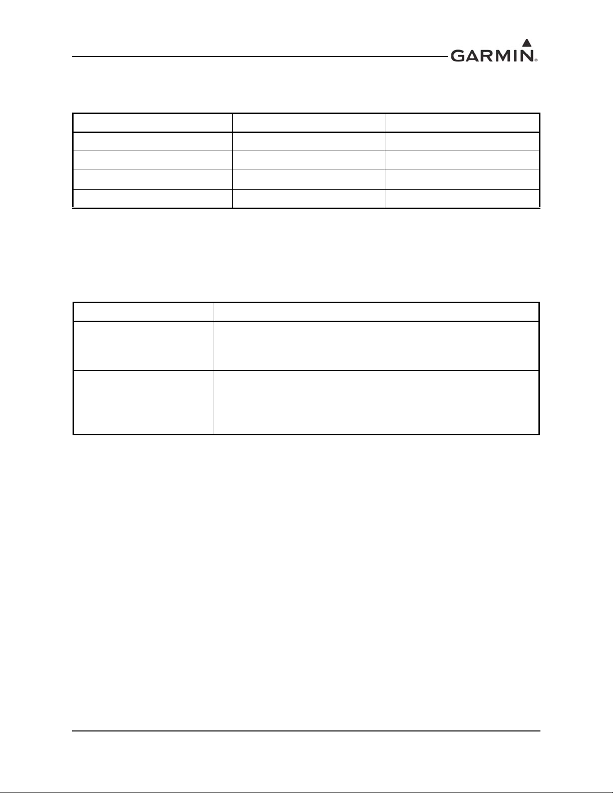
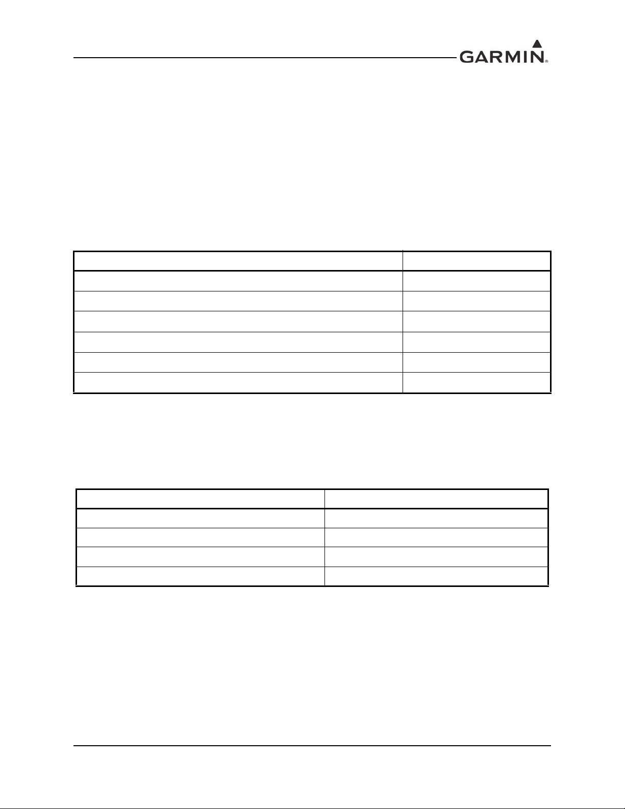
Table 1-3. GMA 35 Speaker Output (1 output, pilot selectable)
Aircraft Voltage Speaker Impedance Output Power
14V 8 Ohms Not recommended
14V 4 Ohms 3 W
28V 8 Ohms 7 W
28V 4 Ohms 10 W
Distortion: <10% THD+N full power, <3% THD+N @ 10% power
3dB Frequency Response Bandwidth: 350 Hz to 6.5 kHz
1.3.3 Power Requirements
Table 1-4. GMA 35 Power Requirements
Characteristic Specification
14 Vdc or 28 Vdc. See the Environmental Qualification Form for
Power Input Voltage
Power Consumption
details on surge ratings and minimum/maximum
operating voltages.
0.8 A @ 14 V (typical)
1.5 A @ 14 V (maximum)
0.4 A @ 28 V (typical)
1.0 A @ 28 V (maximum)
190-00858-11 GMA 35/35c Installation Manual
Rev. H Page 1-4
Page 13
1.4 Certification
The conditions and tests required for TSO/ETSO approval of this article are minimum performance
standards. It is the responsibility of those installing this article either on or within a specific type or class of
aircraft to determine that the aircraft installation conditions are within the TSO/ETSO standards.
TSO/ETSO articles must have separate approval for installation in an aircraft. The article may be installed
only if performed under 14 CFR part 43 or the applicable airworthiness requirements.
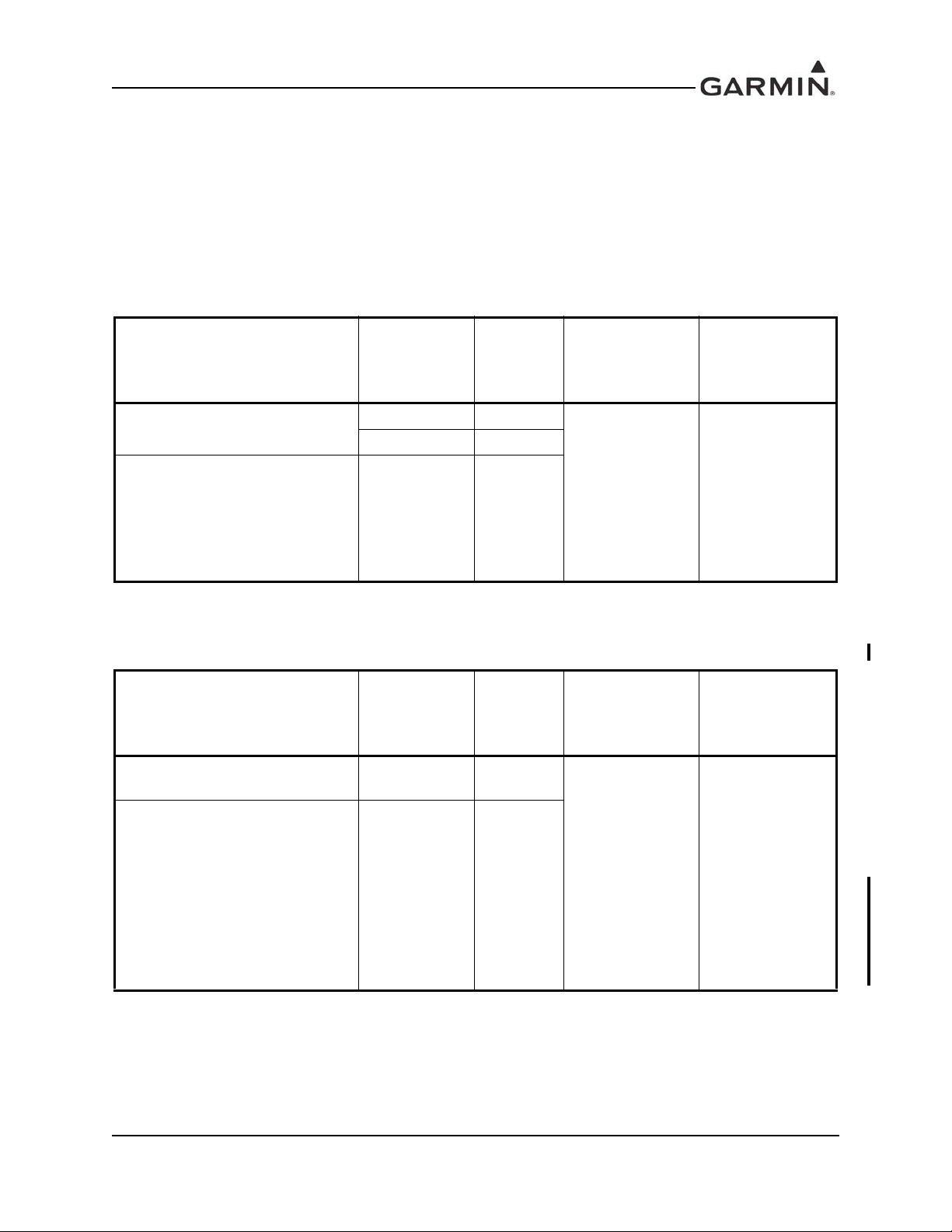
1.4.1 TSO/ETSO Compliance
Table 1-5. GMA 35 (011-02299-00) TSO/ETSO Compliance
Applicable
LRU Boot
Block Part
Numbers
All
006-B0772-B(_)
except
006-B0772-BA
and all
006-B0773-B(_)
except
006-B0773-BA
Function TSO/ETSO Category
Airborne Radio Marker
Receiving Equipment
Aircraft Audio Systems and
Equipment
TSO-C35d A
ETSO-2C35d
TSO-C139
ETSO-C139
Class Ib
Applicable LRU
SW Part
Number
006-B0772-0(_)
006-B0772-5(_)
006-B0773-0(_)
006-B0773-5(_)
Table 1-6 GMA 35 (011-02299-20) and GMA 35c (011-02299-40) TSO/ETSO Compliance
Applicable
LRU Boot
Block Part
Numbers
All
006-B2013-B(_)
except
006-B2103-BA
through
006-B2103-BD
and all
006-B2104-B(_)
except
006-B2104-BA
through
006-B2104-BD
Function TSO/ETSO Category
Airborne Radio Marker
Receiving Equipment
Aircraft Audio Systems and
Equipment
Applicable LRU
SW Part
Number
TSO-C35d A
006-B2103-0(_)
006-B2104-0(_)
TSO-C139 Class Ib
190-00858-11 GMA 35/35c Installation Manual
Rev. H Page 1-5
Page 14
1.4.2 TSO/ETSO Deviations
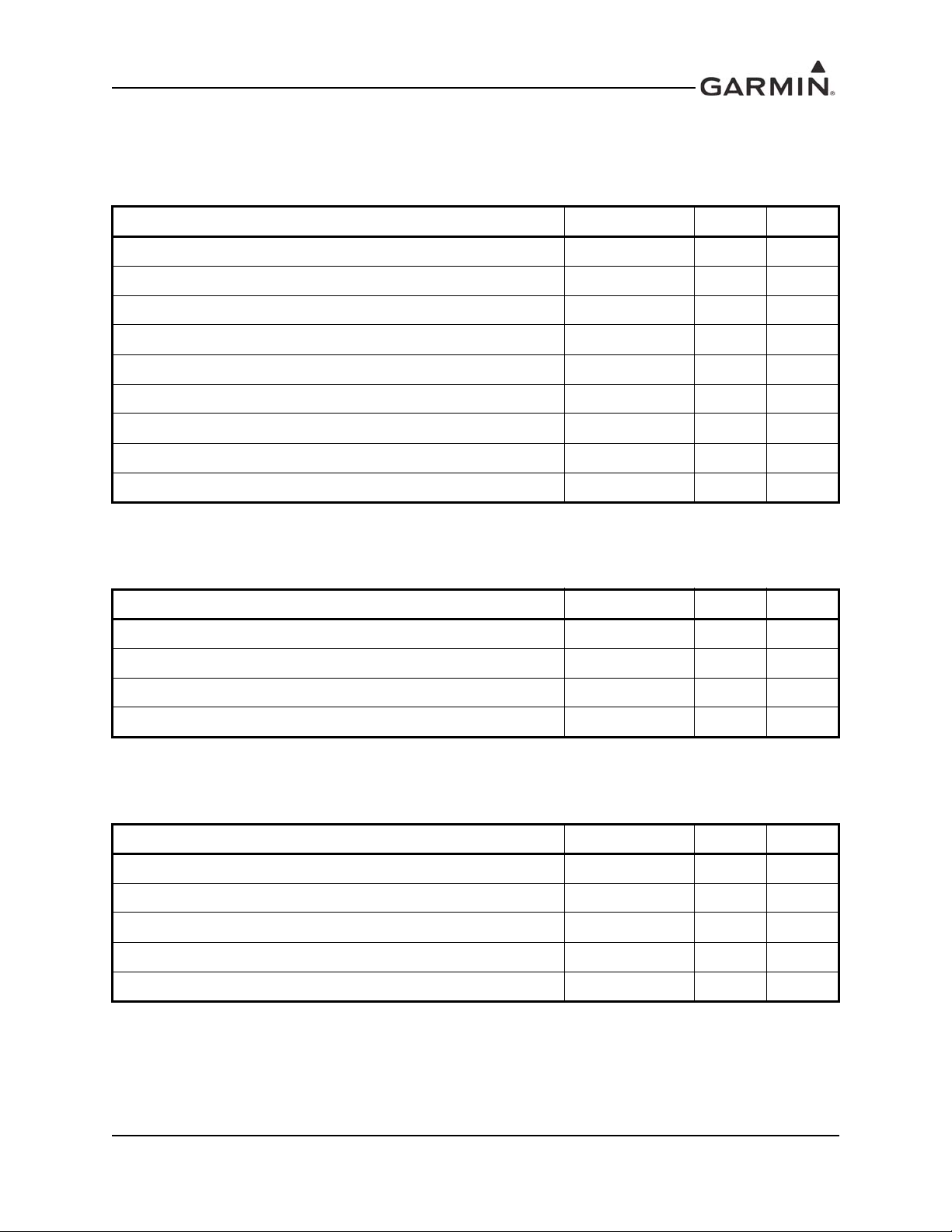
Table 1-7. GMA 35 (011-02299-00) TSO/ETSO Deviations
TSO/ETSO Deviation
TSO-C35d 1. Garmin was granted a deviation from TSO-C35d to use FAR §21.607(d)
instead of FAR §37.7 as the general rules governing holders of the TSO
authorizations.
2. Garmin was granted a deviation from TSO-C35d to use RTCA DO-160E
instead of RTCA DO-138 as the standard for Environmental Conditions and
Test Procedures for Airborne Equipment.
ETSO-2C35d 1. Garmin was granted a deviation from ETSO-2C35d which calls out
EUROCAE 1/WG7 Section 3.16.
TSO-C139 1. Garmin was granted a deviation from TSO-C139 paragraph 7a.
2. Garmin was granted a deviation from TSO-C139 paragraph 7b.
Table 1-8 GMA 35c (011-02299-20 and -40) TSO/ETSO Deviations
TSO/ETSO Deviation
TSO-C35d 1. Garmin was granted a deviation from TSO-C35d to use FAR §21.607(d)
instead of FAR §37.7 as the general rules governing holders of the TSO
authorizations.
2. Garmin was granted a deviation from TSO-C35d to use RTCA DO-160E
instead of RTCA DO-138 as the standard for Environmental Conditions and
Test Procedures for Airborne Equipment.
TSO-C139 1. Garmin was granted a deviation from TSO-C139 paragraph 7a.
2. Garmin was granted a deviation from TSO-C139 paragraph 7b.
190-00858-11 GMA 35/35c Installation Manual
Rev. H Page 1-6
Page 15
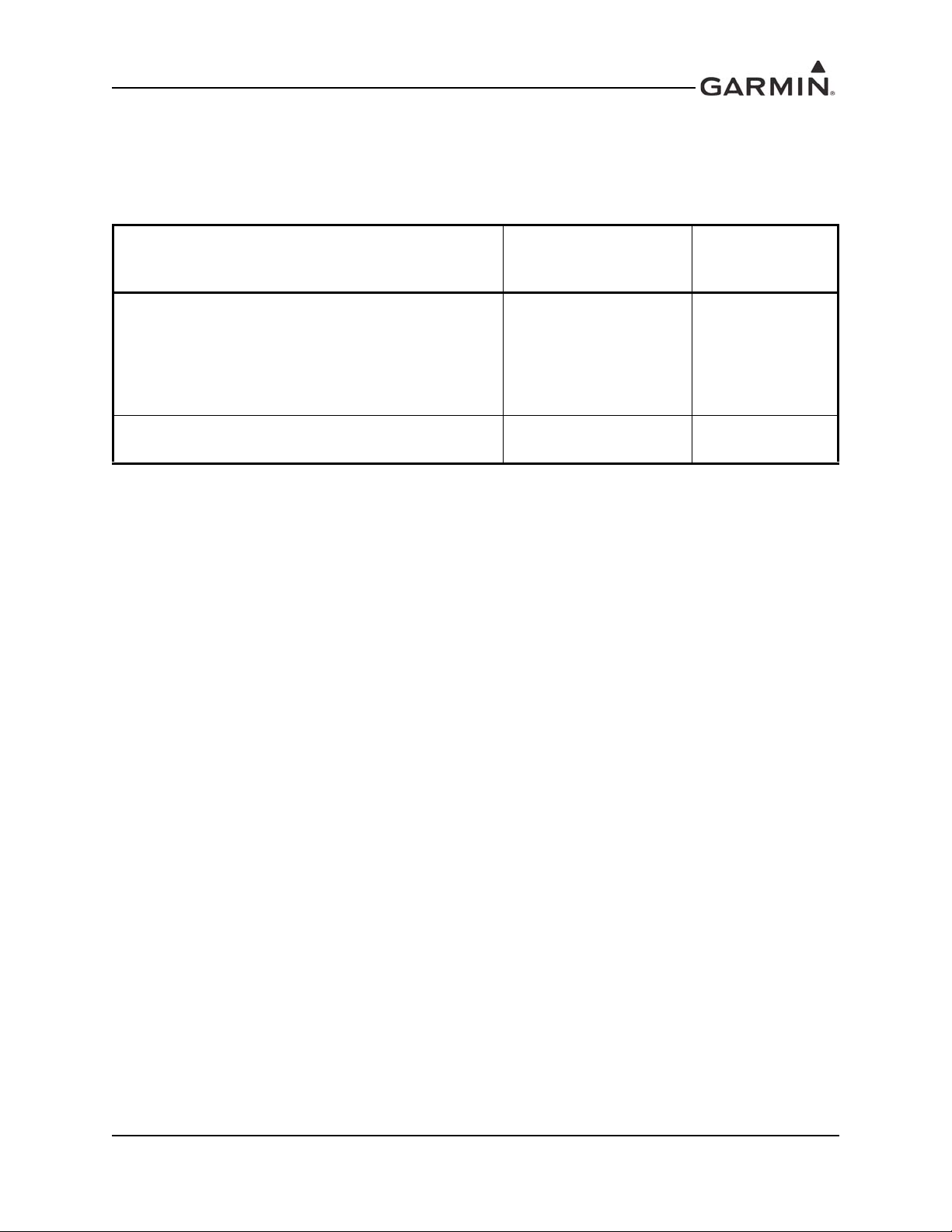
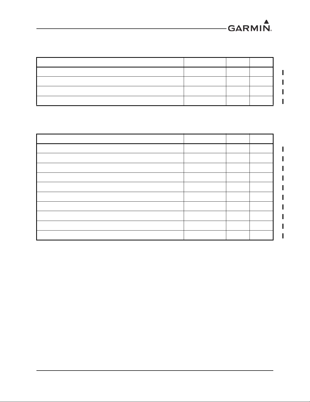
1.4.3 Non-TSO Functions
These function were tested to RTCA/DO-160E environmental qualifications and were demonstrated only
when the GMA 35 is installed as a component of a Garmin Integrated Flight Deck.
Table 1-9. GMA 35 Non-TSO Functions
Applicable LRU
Functions Design Assurance
Automatic Speech Recognition (ASR) RTCA/DO-178B Level D
Software Part
Numbers
006-B0772-0(_)
006-B0772-5(_)
006-B0773-0(_)
006-B0773-5(_)
006-B2103-0(_)
006-B2104-0(_)
Wireless Data Conversion RTCA/DO-178B Level E
006-B2103-0(_)
006-B2104-0(_)
190-00858-11 GMA 35/35c Installation Manual
Rev. H Page 1-7
Page 16

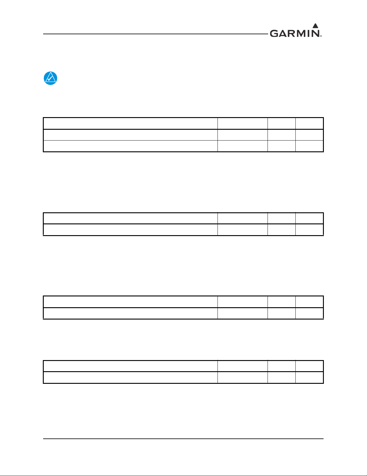
1.4.4 Transmitter Grant of Equipment Authorization
NOTE
NOTE
FCC ID: IPH- 0163700
IC: 1792A-0163700
IC M/N: GMN-00831
This device complies with Part 15 of the FCC rules. Operation is subject to the following
conditions: (1) This device may not cause harmful interference, and (2) this device must
accept any interference received, including interference which may cause undesired
operation.
This device does not contain any user-serviceable parts. Repairs should only be made by
an authorized Garmin service center. Unauthorized repairs or modifications could result
in permanent damage to the equipment, and void your warranty and your authority to
operate this device under Part 15 regulations.
Industry Canada Statement
This device complies with Industry Canada license-exempt RSS standard(s). Operation is subject to the
following two conditions: (1) this device may not cause interference, and (2) this device must accept any
interference, including interference that may cause undesired operation of the device.
Cet appareil est conforme aux normes RSS sans licence d’Industrie Canada. Son fonctionnement est
soumis aux conditions suivantes: (1) cet appareil ne doit pas causer d’interférences et (2) doit accepter
toute interférence,y compris les interférences pouvant entraîner un fonctionnement indésirable de
l’appareil.
Under Industry Canada regulations, this radio transmitter may only operate using an antenna of a type and
maximum (or lesser) gain approved for the transmitter by Industry Canada. To reduce potential radio
interference to other users, the antenna type and its gain should be so chosen that the equivalent
isotropically radiated power (e.i.r.p.) is not more than that necessary for successful communication.
Conformément à la réglementation d'Industrie Canada, le présent émetteur radio peut fonctionner avec une
antenne d'un type et d'un gain maximal (ou inférieur) approuvé pour l'émetteur par Industrie Canada. Dans
le but de réduire les risques de brouillage radioélectrique à l'intention des autres utilisateurs, il faut choisir
le type d'antenne et son gain de sorte que la puissance isotrope rayonnée équivalente (p.i.r.e.) ne dépasse
pas l'intensité nécessaire à l'établissement d'une communication satisfaisante.
This radio transmitter (IC: 1792A-0163700) has been approved by Industry Canada to operate with the
antenna types listed below with the maximum permissible gain and required antenna impedance for each
antenna type indicated. Antenna types not included in this list, having a gain greater than the maximum
gain indicated for that type, are strictly prohibited for use with this device.
Le présent émetteur radio (IC: 1792A-0163700) a été approuvé par Indu strie Canada pour fonctionner avec
les types d'antenne énumérés ci-dessous et ayant un gain admissible maximal et l'impédance requise pour
chaque type d'antenne. Les types d'antenne non inclus dans cette liste, ou dont le gain est supérieur au gain
maximal indiqué, sont strictement interdits pour l'exploitation de l'émetteur.
Antenna Type: 2.4 GHz Rubber Duck Stub Antenna - Rigid 90° RP-SMA Plug
Antenna Gain: 0 dBi
190-00858-11 GMA 35/35c Installation Manual
Rev. H Page 1-8
Page 17

RF Exposure Compliance Statement
This equipment complies with FCC radiation exposure limits set forth for an uncontrolled environment.
This equipment should be installed and operated with minimum distance 20cm between the radiator and
your body. This transmitter must not be co-located or operating in conjunction with any other antenna or
transmitter.
190-00858-11 GMA 35/35c Installation Manual
Rev. H Page 1-9
Page 18

1.5 Reference Documents
The following publications are sources of additional information for installing the GMA 35. Before
installing the unit, the technician should read all relevant referenced materials along with this manual.
Table 1-10. GMA 35 Reference Documents
Part Number Document
190-00858-13 GMA 35 Maintenance Manual
190-01007-02 GTN 7XX Installation Manual
190-00858-11 GMA 35/35c Installation Manual
Rev. H Page 1-10
Page 19

1.6 Operating Instructions
NOTE
This section contains generic operating instructions for TSO purposes only and is not to be used in place of
field operating instructions.
Always refer to applicable airframe specific documentation for instructions on GX000
system operation. This documentation can be found on www.garmin.com.
All user interface is accomplished through a separate touchscreen controller.
1.6.1 Intercom
Touch the appropriate link arrow to enable the following intercom modes:
• All Intercom Mode (Pilot, Copilot, and Passengers)
• Copilot-Passenger Intercom Mode
• Pilot-Copilot Intercom Mode
• Pilot-Passenger Intercom Mode
• All Isolate Mode
• Pilot-Passenger/Copilot-Passenger Intercom Mode
• Pilot-Passenger/Pilot-Copilot Intercom Mode
• Copilot-Passenger/Pilot-Copilot Intercom Mode
1.6.2 Adjusting Intercom Volume
1. Touch the Intercom Button on the touchscreen controller to display the Intercom Screen.
2. Touch the Pilot Volume, Copilot Volume, or Passenger Volume button to display the Pilot, Copilot,
or Passenger Settings Screen.
3. Adjust the volume by using the middle knob or by sliding your finger on the volume slider.
1.6.3 Adjusting Intercom Squelch
1. Touch the Intercom Button on the touchscreen controller to display the Intercom Screen.
2. Touch the Pilot Volume, Copilot Volume, or Passenger Volume button to display the Pilot, Copilot,
or Passenger Intercom Settings Screen.
3. Touch the Squelch Mode Button to turn off Auto Squelch.
4. Adjust the squelch by using the middle knob or by sliding your finger on the squelch slider.
1.6.4 Passenger Address System
1. Touch the Audio & Radios Button on the touchscreen controller to display the Audio & Radios
Screen.
2. If necessary, touch the Copilot Tab.
3. If necessary, touch the Sync to Pilot Button to disable synchronizing selections to the pilot.
4. Scroll the list to find the PA.
5. Touch the PA Button on the Audio & Radios Screen to select the PA for transmission.
190-00858-11 GMA 35/35c Installation Manual
Rev. H Page 1-11
Page 20

1.6.5 Digital Clearance Player
1. Touch the Audio & Radios Button on the touchscreen controller to display the Audios & Radios
Screen.
2. If necessary, touch the Pilot Tab.
3. Scroll the list to find Playback.
4. Touch the Play Button to play the last recorded memory block. The Stop Button is displayed while
the audio is playing. Touch the Stop Button during play of a memory block to stop play. When the
present memory block has finished playing the Play Button is displayed again.
5. Touch the Previous Button to play the previously recorded memory block. Each subsequent press
of the Previous Button selects the previously recorded memory block, if any exist.
6. Touch the Next Button to play the next recorded memory block. Each subsequent press of the
Next Button selects the next recorded memory block, if more exist.
1.6.6 Selecting/deselecting MUSIC1/MUSIC2 input:
1. Touch the Audio & Radios button on the touchscreen controller to display the Audio & Radios
Screen.
2. If necessary, touch the Copilot Tab or the Pass Tab.
3. If necessary, touch the Sync to Pilot Button to disable synchronizing selections to the pilot.
4. Scroll the list to find Music1 or Music2.
5. Touch the Mute Settings Button associated with Music1 or Music2 to display the Mute Settings
Window.
6. Select any of the Intercom, Radio Inputs, or Aural Alerts Buttons to select which items will mute
Music1 or Music2.
190-00858-11 GMA 35/35c Installation Manual
Rev. H Page 1-12
Page 21
2 INSTALLATION OVERVIEW
2.1 Introduction
This section provides hardware equipment information for installing the GMA 35 Audio Panel, related
hardware and optional accessories. Installation of the GMA 35 should follow the data detailed in this
manual. Cabling is fabricated by the installing agency to fit each particular aircraft. The guidance of FAA
advisory circulars AC 43.13-1B and AC 43.13-2B, where applicable, ma y be found useful for making
retro-fit installations that comply with FAA regulations.
2.2 Installation Materials
The GMA 35 is available as a single unit under the following part number:
Table 2-1. GMA 35 Part Number
Item Catalog Part Number
GMA 35, Unit Only, (011-02299-00)
GMA 35, Standard, (011-02299-00)
GMA 35, Unit Only, (011-02299-20)
GMA 35, Standard, (011-02299-20)
GMA 35c, Unit Only, (011-02299-40)
GMA 35c, Standard, (011-02299-40)
*Includes GMA 35 Connector Kit (011-02302-00).
010-00831-00*
010-00831-21*
010-00831-41*
2.2.1 Equipment Available
Each of the following accessories are provided separately from the GMA 35.
Table 2-2. GMA 35 Accessories
Item Garmin Part Number
Connector Kit, GMA 35 011-02302-00
Backplate, GMA 35 011-02300-00
Install Rack, GMA 35 011-02645-00
Bluetooth Antenna/Cable Kit, GMA 35c 011-03909-00
010-00831-00
010-00831-20
010-00831-40
2.2.2 Additional Equipment Required
• Cables: The installer will fabricate and supply all system cables. Interconnect wiring diagrams are
detailed in Appendix C.
• Stereo headphone jacks (up to 4), microphone jacks (up to 4), 3.5mm stereo jacks (up to 2)
Insulating type jacks or insulating washers should be used for all jacks to isolate them from aircraft
chassis.
190-00858-11 GMA 35/35c Installation Manual
Rev. H Page 2-1
Page 22

2.3 Installation Considerations
NOTE
The GMA 35 interfaces with various avionics equipment. Fabrication of a wiring harness is required.
Sound mechanical and electrical methods and pr actices are required for installation of the GMA 35.
2.3.1 Marker Beacon Antenna Installation
2.3.1.1 Location Considerations
The marker beacon antenna should be mounted on a flat surface on the underside of the aircraft body.
Do not install the antenna inside the aircraft. Installing the antenna inside the aircraft
limits the antenna reception and increases the antennas susceptibility to radiation from
components inside the aircraft.
Mount the antenna so that there is a minimum of structure between it and the ground radio stations. Locate
it as far away as possible from transmitter antennas.
2.3.1.2 Marker Beacon Antenna Mounting
Install the antenna according to the antenna manufacturer’s instructions. If the antenna is being installed on
a composite aircraft, ground planes must sometimes be added. Conductive wire mesh, radials or thin
aluminum sheets embedded in the composite material provide the proper ground plane allowing the
antenna pattern (gain) to be maximized for optimum performance.
2.3.1.3 Marker Beacon Antenna Cable
Use coaxial cable meeting the applicable aviation regulation for the marker beacon antenna. Any cable
meeting specifications is acceptable for the installation. When routing antenna cables, observe the
following precautions:
• All cable routing should be kept as short and as direct as possible
• Avoid sharp bends
• Avoid routing cables near power sources (e.g., 400 Hz generators, trim motors, etc.) or near power
for fluorescent lighting
• Allow a 12 inch minimum separation between any other cables, including antenna cables (e.g
ADF, COM, NAV, GS, MARKER)
190-00858-11 GMA 35/35c Installation Manual
Rev. H Page 2-2
Page 23
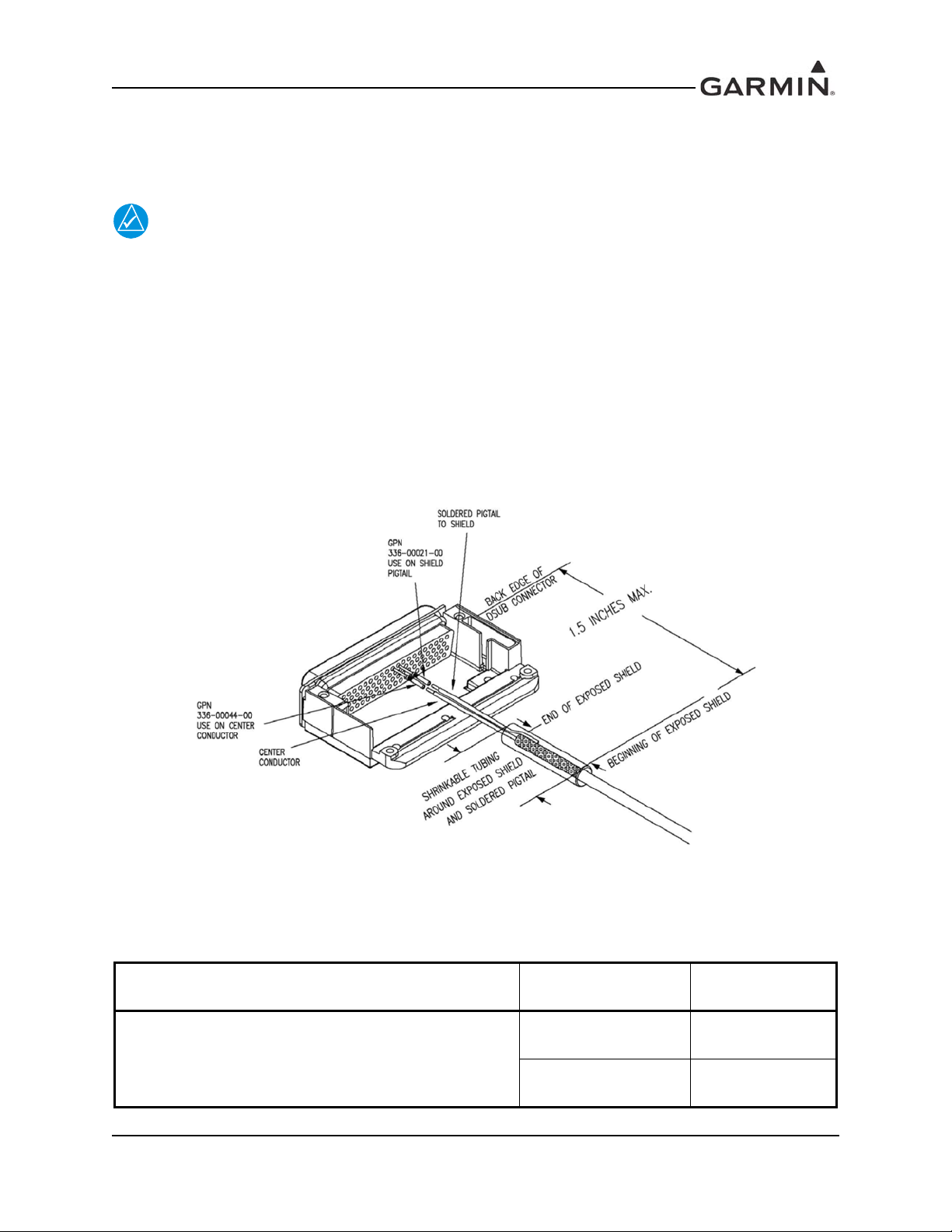
2.3.1.4 Marker Beacon Antenna Cable Installation
NOTE
This section provides guidance for terminating the coaxial cable into the D-Sub connector. See the system
interconnect section for pin assignments.
Use coaxial cable meeting the applicable aviation regulation for the marker beacon
antenna. Route the cable to the D-Sub as described in Section 2.3.1.3.
When terminating the coaxial cable into the D-Sub observe the following guidance (refer to Figure 2-1):
• Keep the distance from the end of the exposed shield to D-Sub as short as possible.
• Ensure the distance from the beginning of the exposed shield to D-Sub is no more than 1.5 inches
long.
• Terminate the center conductor by directly connecting it to the D-sub through a crimp pin
without
a pigtail.
Figure 2-1 below represents a suggested method for terminating the marker beacon coaxial cable using
M17/128-RG400 terminated into a high density D-Sub connector. Refer to Table 2-1 for Crimp Tool, Pin,
and Crimp Tool Insert part numbers.
Figure 2-1. GMA Marker Beacon Coaxial Cable D-Sub Termination
Table 2-3. Pin and Crimp Tool Part Numbers
CRIMP TOOL PIN
DANIELS MANUFACTURING CORP
DMC M22520/2-01 GAGE
AFM8 CRIMPING TOOL
Garmin Part Number
336-00021-00
Garmin Part Number
336-00044-00
CRIMP TOOL
INSERT
K42
K774
190-00858-11 GMA 35/35c Installation Manual
Rev. H Page 2-3
Page 24

2.3.1.5 Bluetooth Antenna/Cable Kit Installation (GMA 35c only)
This section provides guidance for installing the Bluetooth antenna/cable kit, required for proper Bluetoot h
function.
Choose a location to mount the Bluetooth antenna that is within reach of the GMA 35c rack. Ensure the
Bluetooth antenna is mounted in a location that is free from conducting obstructions between the antenna
and crew/passenger cabin locations where Bluetooth connection access is desired.
1. Connect the right angle SMA end of the antenna cable to the Bluetooth SMA connector at the front
of the GMA 35c (J3504).
2. Secure the RP-SMA antenna connector end of the antenna cable to a mounting hole in the desired
antenna location using the provided mounting hardware.
3. Attach the Bluetooth antenna to the antenna cable RP-SMA connector. See assembly diagram in
Appendix B for mounting hole diameter, maximum panel thickness, and assembly details.
2.4 Cabling & Wiring
Refer to the interconnect examples in Appendix C for wire gauge guidance.
In some cases, a larger gauge wire such as AWG #18 or #20 may be needed for power connections. If
using AWG #18 barrel contacts, ensure that no two contacts are mounted directly adjacent to each other.
This minimizes the risk of contacts touching and shorting to adjacent pins and to ground.
Use wire and cable meeting the applicable aviation regulation. When routing wire and cable, observe the
following precautions:
• Keep wire and cable as short and direct as possible
• Avoid sharp bends
• Avoid routing near power sources (e.g. 400 Hz generators, trim motors, etc) or near power of
fluorescent lighting
2.5 Cooling Air
The GMA 35 does not have provisions for attaching cooling air, however the thermal characteristics of
the installation should always be assessed. An undesirable thermal condition could be created due to the
unit's own internal power dissipation combined with restricted ventilation, or due to heat generated by
adjacent equipment. Limiting thermal build up, by means of fan or natural convection is always a good
practice and recommended to increase the product life.
190-00858-11 GMA 35/35c Installation Manual
Rev. H Page 2-4
Page 25

2.6 Mounting Requirements
The GMA 35 mounting surface must be capable of providing structural support and electrical bond to the
aircraft to minimize radiated EMI and provide protection from High-Intensity Radiation Fields (HIRF).
The GMA 35 is mounted using its own unit rack (Figure 2-2) which attaches directly to a GTN 7XX unit
rack. Refer to Appendix B for installation drawings. The installer must provide any additional remote
mounting equipment.
Figure 2-2. GMA 35 Unit Rack
190-00858-11 GMA 35/35c Installation Manual
Rev. H Page 2-5
Page 26

2.7 Installation Approval Considerations for Pressurized Aircraft
Antenna and cable installations on pressurized cabin aircraft require FAA approved installation design and
engineering substantiation data whenever such installations incorporate alteration (penetration) of the
cabin pressure vessel by connector holes and/or mounting arrangements.
For needed engineering support pertaining to the design and approval of such pressurized aircraft antenna
installations, it is recommended that the installer proceed according to any of the following listed
alternatives:
1. Obtain approved antenna installation design data from the aircraft manufacturer.
2. Obtain an FAA approved Supplemental Type Certificate (STC) pertaining to and valid for the
subject antenna installation.
3. Contact the FAA Aircraft Certification Office in the appropriate Region and request identification
of FAA Designated Engineering Representatives (DERs) who are authorized to prepare and
approve the required antenna installation engineering data.
4. Locate an appropriate consultant FAA DER, by reviewing the “FAA Consultant DER Directory”,
which can be found at the FAA “Designee and Delegation” web page.
5. Contact an aviation industry or ganization such as the Aircraft Electronics Association and request
their assistance.
2.8 Electrical Noise
Because the audio panel is a point in the aircraft where signals from many pieces of equipment are brought
together, take care to minimize effects from coupled interference and ground loops.
Coupled interference can sneak into audio system interconnecting cables when they are routed near large
AC electric fields, AC voltage sources and pulse equipment (strobes, spark plugs, magnetos, EL displays,
CRTs, etc). Interference can also couple into audio system interconnecting cables by magnetic induction
when they are routed near large AC current-carrying conductors or switched DC equipment (heaters,
solenoids, fans, autopilot servos, etc).
Ground loops are created when there is more than one path in which return currents flow or when signal
returns share the same path as large currents from other equipment. These large currents create differences
in ground potential between the various equipment operating in the aircraft. These differences in potential
can produce an additive effect on audio panel input signals.
The audio panel may “see” the desired input signal plus an unwanted component injected by ground
differentials, a common cause of alternator-related noise. This is the main reason why all audio jacks
should be isolated from ground. Terminating audio shields just at one end eliminates another potential
ground loop injection point.
Single-point grounding cannot be overstressed for the various avionics producing and processing audio
signals. Single-point, in this context, means that the various pieces of equipment share a single common
ground connection back to the airframe. Good aircraft electrical/charging system ground bonding is also
important.
The wiring diagrams and accompanying notes in this manual should be followed closely to minimize noise
effects.
190-00858-11 GMA 35/35c Installation Manual
Rev. H Page 2-6
Page 27

3 INSTALLATION PROCEDURE
CAUTION
3.1 Unpacking Unit
Carefully unpack the equipment and make a visual inspection of the unit for evidence of damage incurred
during shipment. If the unit is damaged, notify the carrier and file a claim. To justify a claim, save the
original shipping container and all packing materials. Do not return the unit to Garmin until the carrier has
authorized the claim.
Retain the original shipping containers for storage. If the original containers are not available, a separate
cardboard container should be prepared that is large enough to accommodate sufficient packing material to
prevent movement.
3.2 Antenna Installation
Install the antenna according to the antenna manufacturer's instructions.
3.3 Antenna Cable Connectors
The antenna cable requires a BNC plug connector. Follow BNC connector manufacturer instructions for
assembly of the BNC connector.
3.4 Electrical Connections
All electrical connections to the GMA 35, including marker beacon antenna and shield ground, are make
through two 44-pin D-subminiature connectors. Tables in Section 4 define the electrical characteristics of
all input and output signals. Required connector and associated hardware are supplied in the connector kit
(Connector Kit, GMA 35 P/N 011-02302-00, RF Cable Kit, GMA 35c 011-03909-00). See figures in
Appendix C for interconnect wiring diagrams.
Check wiring connections for errors before inserting the GMA 35 into the rack. Incorrect
wiring could cause internal component damage.
Table 3-1. Pin Contact Part Numbers
Manufacturer
(Note 1)
Garmin P/N 336-00044-00 336-00021-00
Military P/N N/A M39029/58-360
44 pin D-Subminiature (P3501, 3502)
18-20 AWG
(Power Only)
22-28 AWG
190-00858-11 GMA 35/35c Installation Manual
Rev. H Page 3-1
Page 28
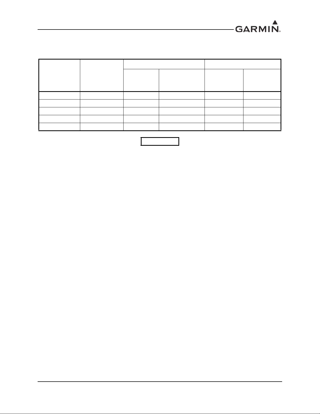
Table 3-2. Recommended Crimp Tools
18-20 AWG 22-28 AWG
Manufacturer
(Note 1)
Military P/N M22520/2-01 N/A M81969/1-04 M22520/2-09 M81969/1-04
Positronic 9507 9502-11 M81969/1-04 9502-3 M81969/1-04
AMP 601966-1 N/A 91067-1 601966-6 91067-1
Daniels AFM8 K774 M81969/1-04 K42 M81969/1-04
Astro 615717 N/A M81969/1-04 615725 M81969/1-04
Hand
Crimping Tool
Positioner
Insertion/
Extraction Tool
(Note 2)
Positioner
Insertion/
Extraction
Tool
NOTES
1. Non-Garmin part numbers shown are not maintained by Garmin and consequently are subject to
change without notice.
2. Extracting the #18 and #20 contacts requires that the expanded wire barrel be cut off from the
contact. It may also be necessary to push the pin out from the face of the connector when using an
extractor due to the absence of the wire. A new contact must be used when reassembling the
connector.
3.5 Backshell Assembly
The GMA 35 connector kit includes two Garmin backshell assemblies. Garmin’s backshell connectors
give the installer the ability to quickly and easily terminate shield grounds at the backshell housing using
the Shield Block. To assemble the backshell connectors and grounding system, refer to instructions
provided in the Shield Block Installation Instructions (190-00313-09).
190-00858-11 GMA 35/35c Installation Manual
Rev. H Page 3-2
Page 29

3.6 GMA 35 Unit Installation
CAUTION
Do not use excessive force when inserting the GMA 35 into the rack. This may damage the
connectors, unit, and/or rack. If heavy resistance is felt during installation, stop! Remove
the GMA 35 and identify the source of resistance.
For final installation and assembly, refer to the outline and installation drawings shown in Appendix B of
this manual.
1. Assemble the backshell as described in Section 3.5.
2. Connect both backshells to the rear plate using the screws provided in the connector kit.
3. Mount the GMA 35 rack to the GTN rack as shown in Appendix B. Refer to the GTN 7XX
Installation Manual for GTN installation rack guidance.
4. Assemble the rear plate into the GMA 35 unit rack.
5. Insert the GMA 35 into the rack, n oting prop er orientatio n as shown on the installation drawing in
Appendix B.
6. Lock the GMA 35 in place using the appropriate size hex wrench.
190-00858-11 GMA 35/35c Installation Manual
Rev. H Page 3-3
Page 30

3.7 Post Installation Configuration & Checkout
NOTE
NOTE
NOTE
NOTE
The GMA 35 does not provide valid outputs until the aircraft post installation
configuration procedures are co mpleted.
3.7.1 Verify Failsafe Operation with a Mono Headset
1. Remove power to the unit by pulling the audio breaker.
2. Connect a mono headset to the pilot’s headset output jack and pilot’s mic jack.
Use of a true mono headset is required for this test to ensur e pr oper wiring even if a ster eo
jack is provided in the installation. Wiring left channel (tip contact) and right channel
(ring contact) backwards will cause failsafe mode not to f unction with mono headsets. Use
of a true mono headset is required for this test (not a stereo headset with a mono/stereo
switch because headset manufactures differ on how they accomplish this switching). This
will guarantee the condition of the right channel (ring terminal) being shorted to the
return (sleeve terminal) by the mono headset’s plug. This short occurs because of the
physical design of the headset plug contacts and is an inevitable consequence of plugging
a mono headset into a stereo ja ck. Duri ng power-on operation, this short will not damage
the audio panel.
3. Verify that the COM1 transceiver can be heard in the pilot’s headset.
4. Verify that COM1 can key and transmit the pilot’s mic audio by verifying received sidetone or
checking reception of the transmission with another radio tuned to receive this transmission (verify
Pilot PTT and mic operation is delivered to this transceiver).
5. Apply unit power by restoring the audio breaker to the normal operating position.
3.7.2 Verify Installed Transceivers (COMs) are able to Transmit and Receive
1. Connect a headset to the pilot’s headset output and mic input jack.
2. Verify that each installed transc eiver (COM) can be heard when selected.
Depending on settings, the mic selected COM may mute audio from other COMs.
3. Verify that each installed transceiver keys for transmission and transmits clear audio from the
pilot’s mic when selected for transmission and the Pilot PTT key is pressed.
The audio panel can be configured to simulate received sidetone internally, verifying
transmission with a separate radio not in the system is recommended.
190-00858-11 GMA 35/35c Installation Manual
Rev. H Page 3-4
Page 31

NOTE
Depending on configuration and sometimes COM system wiring, other transceivers may
NOTE
NOTE
be muted during transmit. Also, the audio panel may mute the speaker during PTT.
4. Move the headset to the copilot’ s headset jacks and verify that any one of the installed transceivers
(testing each is not necessary) receives and transmits copilot mic properly as above.
3.7.3 Verify Audio from Installed Receiver and Alert Sources
1. Connect a headset to the pilot’s headset output and mic input jack (depending on configuration and
ICS mode, copilot or passenger positions may not hear all of these sources).
2. Verify each installed receiver (NA V/ADF/DME) can be heard when selected (use test signal gener ators/transmitters when necessary).
3. Verify each installed unswitched (alert) source can be heard when the source is instructed to play a
simulated alert/message.
3.7.4 Verify Speaker Output (if installed)
1. Select the speaker output and verify any one transceiver or receiver is heard clearly.
2. Verify that any one unswitched (alert) source is heard clearly in the speaker (depending on configuration, these may be heard in the speaker regardless of speaker selection).
3. Initiate PA (Passenger Address) mode and verify that from both the pilot and copilot position the
crew position that is pressing PTT has their mic delivered to the speaker clearly.
If a loud squeal is heard while testing PA, it is because there is too much acoustic feedback
between the speaker and the mic. If they cannot be placed further apart, a lower volume
configuration should be used. In some installations, there is insufficient distance between
the speaker and crew seat positions for PA to speaker to reliably operate. In these
conditions, the “PA to speaker” volume can be set very low and PA audio will still be
delivered to the headsets.
3.7.5 Verify ICS (Intercom System) Operation
1. Place the audio panel into all ICS mode (refer to the applicable pilot’s guide) so that all ICS
positions hear all others.
2. Deselect or turn off other audio sources (MKR, transceivers, receivers, alerts).
Some configurations may mute passenger intercom audio to crew when aircraft audio is
present.
3. From the pilot headset position, verify the pilot, copilot, and all passenger mic inputs can be heard
in the pilot’s headset when speaking into the mic input under test (adjust pilot ICS volume if
necessary).
4. Speak into the pilot’s mic and verify that pilot mic audio is heard in the copilot headset (adjust
copilot ICS volume if necessary) and in each passenger headset (adjust passenger ICS volume if
necessary).
190-00858-11 GMA 35/35c Installation Manual
Rev. H Page 3-5
Page 32

3.7.6 Verify Telephone and Music Operation (if installed)
NOTE
1. Deselect or turn off other audio sources (MKR, transceivers, receivers, alerts). Some
configurations may mute telephone and/or music audio when aircraft audio is present.
2. From the pilot’s headset position, initiate a phone call and verify that two-way communication
over the telephone can be heard when selected (refer to the applicable pilot’s guide for information
on how telephone and music audio can be distributed and ensure that it is configured to be heard
by the pilot).
3. Verify that all installed music sources can be heard when selected (refer to the applicable pilot’s
guide for information on how telephone and music audio can be distributed and ensure that it is
configured to be heard by the pilot).
3.7.7 Marker Beacon Operation (if installed)
1. With a marker signal generator/transmitter test set, generate Marker Tones.
2. From the pilot headset position, verify that marker audio can be heard when selected.
3. If the system includes integrated lamp annunciation and/or if external lamps are installed, verify
that each marker tone illuminates the proper lamp.
The Marker Lamps will operate even if the marker audio is not selected.
Outer Marker – Blue Lamp – 400 Hz (AM or received audio tone)
Middle Marker – Amber Lamp – 1300 Hz (AM or received audio tone)
Inner Marker – White Lamp – 3000 Hz (AM or received audio tone)
4. If the system is configured and/or wired to allow both HI and LO sensitivity operation, verify that
during HI SENS operation, the RF threshold is more sensitive (marker audio/indication occurs as a
lower RF power).
3.7.8 Other Optionally Installed or Configured Inputs/Outputs
Verify any other installed/configured inputs and outputs operate as described in the applicable pilot’s
guide. Possible examples include PTC (voice command “Push to Command”) keys, ICS keys, Passenger
ISO (isolation) toggle key, clearance recorder Play key, PA Mute output, PA Mode Selected output, Com
Active output, and Middle Marker Sense output.
3.8 Continued Airworthiness
Other than for regulatory periodic functional checks, maintenance of the GMA 35 is “on condition” only.
190-00858-11 GMA 35/35c Installation Manual
Rev. H Page 3-6
Page 33

4 SYSTEM INTERCONNECTS
4.1 Pin List
4.1.1 J3501 Connector
Figure 4-1. View of J3501 connector from back of unit
Table 4-1. J3501 Pin List
Pin Pin Name I/O
1 MARKER ANTENNA IN HI In
2 MARKER ANTENNA IN LO In
3 COM 3 AUDIO IN HI In
4 COM 3 AUDIO LO --
5 COM 3 MIC AUDIO OUT HI Out
6 COM 3 MIC KEY* OUT Out
7 RCVR 4 AUDIO IN HI In
8 RCVR 4 AUDIO IN LO In
9 COM 1 AUDIO IN HI In
10 COM 1 AUDIO LO --
11 COM 1 MIC AUDIO OUT HI Out
12 COM 1 MIC KEY* OUT Out
13 COM 2 AUDIO IN HI In
14 COM 2 AUDIO LO --
15 COM 2 MIC AUDIO OUT HI Out
16 PILOT PTC/ICS KEY* IN In
17 NAV 1 AUDIO IN HI In
18 NAV 1 AUDIO IN LO In
19 NAV 2 AUDIO IN HI In
20 NAV 2 AUDIO IN LO In
21 RCVR 3 AUDIO IN HI In
22 RCVR 3 AUDIO IN LO In
190-00858-11 GMA 35/35c Installation Manual
Rev. H Page 4-1
Page 34

Table 4-1. J3501 Pin List
Pin Pin Name I/O
23 RCVR 5/PASS 5 MIC IN HI (configurable) In
24 COM ACTIVE* OUT Out
25 TEL AUDIO IN HI In
26 TEL AUDIO IN LO In
27 TEL MIC OUT HI Out
28 TEL MIC OUT LO Out
29 ALERT 3 AUDIO IN HI In
30 COM 2 MIC KEY* OUT Out
31 ALERT 1 AUDIO IN HI In
32 ALERT 1 AUDIO IN LO In
33 PILOT MIC AUDIO IN HI In
34 PILOT MIC KEY* IN In
35 PILOT MIC AUDIO IN LO In
36 INNER MARKER LAMP OUT Out
37 OUTER MARKER LAMP OUT Out
38 MIDDLE MARKER LAMP OUT Out
39 MIDDLE MARKER SENSE OUT Out
40 PASS HEADSET AUDIO OUT LEFT Out
41 PASS HEADSET AUDIO OUT RIGHT Out
42 PASS HEADSET AUDIO OUT LO Out
43 ALERT 2,3,4 AUDIO IN LO In
44 ALERT 4 AUDIO IN HI In
*Indicates Active Low (Ground to activate)
190-00858-11 GMA 35/35c Installation Manual
Rev. H Page 4-2
Page 35

4.1.2 J3502 Connector
Figure 4-2. View of J3502 connector from back of unit
Table 4-2. J3502 Pin List
Pin Pin Name I/O
1 PILOT HEADSET AUDIO OUT LO Out
2 COPILOT HEADSET AUDIO OUT LO Out
3 COPILOT HEADSET AUDIO OUT LEFT Out
4 COPILOT HEADSET AUDIO OUT RIGHT Out
5 LIGHTING BUS IN LO In
6 RESERVED --
7 LIGHTING BUS IN HI In
8 AIRCRAFT POWER In
9 AIRCRAFT POWER In
10 POWER GROUND --
11 POWER GROUND --
12 PA MUTE* OUT Out
13 MARKER HI SENS* IN In
14 PASS ISO TOGGLE/ICS KEY* IN In
15 ALERT 2 AUDIO IN HI In
16 PILOT HEADSET AUDIO OUT LEFT Out
17 RS-232 IN In
18 RS-232 OUT Out
19 PA MODE SELECTED* OUT Out
20 COM SWAP/CYCLE* IN In
21 RESERVED --
22 PLAY KEY* IN In
23 MUSIC 1 IN LEFT In
24 MUSIC 1 IN RIGHT In
25 MUSIC 1 IN LO In
26 MUSIC 2 IN LEFT In
190-00858-11 GMA 35/35c Installation Manual
Rev. H Page 4-3
Page 36

Table 4-2. J3502 Pin List
Pin Pin Name I/O
27 MUSIC 2 IN RIGHT In
28 MUSIC 2 IN LO In
29 FAILSAFE WARN AUDIO IN HI In
30 COPILOT PTC/ICS KEY* IN In
31 PILOT HEADSET AUDIO OUT RIGHT Out
32 COPILOT MIC AUDIO IN HI In
33 COPILOT MIC KEY* IN In
34 COPILOT MIC AUDIO IN LO In
35 PASS 1 MIC AUDIO IN HI In
36 PASS 1 MIC AUDIO IN LO In
37 PASS 2 MIC AUDIO IN HI In
38 PASS 2 MIC AUDIO IN LO In
39 PASS 3 MIC AUDIO IN HI In
40 PASS 3 MIC AUDIO IN LO In
41 PASS 4 MIC AUDIO IN HI In
42 PASS 4 MIC AUDIO IN LO In
43 SPEAKER AUDIO OUT LO Out
44 SPEAKER AUDIO OUT HI Out
*Indicates Active Low (Ground to activate)
190-00858-11 GMA 35/35c Installation Manual
Rev. H Page 4-4
Page 37

4.2 Power
4.2.1 Aircraft Power
Table 4-3. Aircraft Power
Pin Name Connector Pin I/O
AIRCRAFT POWER J3502 8 In
AIRCRAFT POWER J3502 9 In
POWER GROUND J3502 10 --
POWER GROUND J3502 11 --
4.3 Serial Data
4.3.1 RS-232
Table 4-4. RS-232
Pin Name Connector Pin I/O
RS-232 IN 1 J3502 17 In
RS-232 OUT 1 J3502 18 Out
The RS-232 outputs conform to EIA Standard RS-232C with an output voltage swing of at least ±5V when
driving a standard RS-232 load.
4.4 Lighting
Table 4-5. Lighting
Pin Name Connector Pin I/O
LIGHTING BUS IN HI J3502 7 In
LIGHTING BUS IN LO J3502 5 In
This input can be configured to control the brightness of the marker lamp and middle marker sense outputs.
190-00858-11 GMA 35/35c Installation Manual
Rev. H Page 4-5
Page 38
4.5 Audio Inputs and Outputs
4.5.1 COM Audio Inputs and Outputs
Table 4-6. COM Audio Inputs and Outputs
Pin Name Connector Pin I/O
COM 1 AUDIO IN HI J3501 9 In
COM 1 AUDIO LO J3501 10 --
COM 2 AUDIO IN HI J3501 13 In
COM 2 AUDIO LO J3501 14 --
COM 3 AUDIO IN HI J3501 3 In
COM 3 AUDIO LO J3501 4 --
COM 1 MIC AUDIO OUT HI J3501 11 Out
COM 2 MIC AUDIO OUT HI J3501 15 Out
COM 3 MIC AUDIO OUT HI J3501 5 Out
4.5.2 NAV Audio Inputs
Table 4-7. NAV Audio Inputs
Pin Name Connector Pin I/O
NAV 1 AUDIO IN HI J3501 17 In
NAV 1 AUDIO LO J3501 18 --
NAV 2 AUDIO IN HI J3501 19 In
NAV 2 AUDIO LO J3501 20 --
4.5.3 Receiver Audio Inputs
Table 4-8. Receiver Audio Inputs
Pin Name Connector Pin I/O
RCVR 3 AUDIO IN HI J3501
RCVR 3 AUDIO IN LO
RCVR 4 AUDIO IN HI
RCVR 4 AUDIO IN LO
RCVR 5/PASS 5 MIC IN HI (configurable)
J3501 22
J3501 7
J3501 8
J3501 23 In
21
In
--
In
--
190-00858-11 GMA 35/35c Installation Manual
Rev. H Page 4-6
Page 39
4.5.4 Telephone
Table 4-9. Telephone
Pin Name Connector Pin I/O
TEL AUDIO IN HI J3501 25 In
TEL AUDIO IN LO J3501 26 In
TEL MIC OUT HI J3501 27 Out
TEL MIC OUT LO J3501 28 Out
4.5.5 Pilot/Copilot
Table 4-10. Pilot/Copilot
Pin Name Connector Pin I/O
PILOT MIC AUDIO IN HI J3501 33 In
PILOT MIC AUDIO IN LO J3501 35 In
COPILOT MIC AUDIO IN HI J3502 32 In
COPILOT MIC AUDIO IN LO J3502 34 In
PILOT HEADSET AUDIO OUT LO J3502 1 Out
PILOT HEADSET AUDIO OUT LEFT J3502 16 Out
PILOT HEADSET AUDIO OUT RIGHT J3502 31 Out
COPILOT HEADSET AUDIO OUT LO J3502 2 Out
COPILOT HEADSET AUDIO OUT LEFT J3502 3 Out
COPILOT HEADSET AUDIO OUT RIGHT J3502 4 Out
190-00858-11 GMA 35/35c Installation Manual
Rev. H Page 4-7
Page 40

4.5.6 Passenger
Table 4-11. Passenger
Pin Name Connector Pin I/O
PASS 1 MIC AUDIO IN HI J3502 35 In
PASS 1 MIC AUDIO IN LO J3502 36 --
PASS 2 MIC AUDIO IN HI J3502 37 In
PASS 2 MIC AUDIO IN LO J3502 38 --
PASS 3 MIC AUDIO IN HI J3502 39 In
PASS 3 MIC AUDIO IN LO J3502 40 --
PASS 4 MIC AUDIO IN HI J3502 41 In
PASS 4 MIC AUDIO IN LO J3502 42 --
RCVR 5/PASS 5 MIC IN HI (configurable) J3501 23 In
PASS HEADSET AUDIO OUT LEFT J3501 40 Out
PASS HEADSET AUDIO OUT RIGHT J3501 41 Out
PASS HEADSET AUDIO OUT LO J3501 42 --
190-00858-11 GMA 35/35c Installation Manual
Rev. H Page 4-8
Page 41

4.5.7 Alert Inputs
CAUTION
Table 4-12. Alert Inputs
Pin Name Connector Pin I/O
ALERT 1 AUDIO IN HI J3501 31 In
ALERT 1 AUDIO IN LO J3501 32 --
ALERT 2 AUDIO IN HI J3502 15 In
ALERT 2,3,4 AUDIO IN LO J3501 43 --
ALERT 3 AUDIO IN HI J3501 29 In
ALERT 4 AUDIO IN HI J3501 44 In
FAILSAFE WARN AUDIO IN HI J3502 29 In
These are unswitched inputs intended for use with alert sources such as altitude, terrain, auto-pilot or other
aural status indications.
FAILSAFE WARN AUDIO IN HI is heard during normal operation as a fifth alert input.
During failsafe mode both FAILSAFE WARN AUDIO IN HI and COM 1 AUDIO INPUT
are connected to the PILOT HEADSET LEFT OUTPUT. During this time the output of the
COM 1 radio and the output of the device connected to FAILSAFE WARN AUDIO IN HI
will become shorted together, potentially causing damage or interference. If the
FAILSAFE WARN AUDIO IN HI is used, it may be necessary to install summing resistors
in series between these sources and the inputs to the audio panel to protect the outputs
from damage.
4.5.8 Speaker Outputs
Table 4-13. Speaker Outputs
Pin Name Connector Pin I/O
SPEAKER AUDIO OUT LO P3502 43 Out
SPEAKER AUDIO OUT HI P3502 44 Out
190-00858-11 GMA 35/35c Installation Manual
Rev. H Page 4-9
Page 42

4.6 Music Inputs
Table 4-14. Music Inputs
Pin Name Connector Pin I/O
MUSIC 1 IN LEFT P3502 23 In
MUSIC 1 IN RIGHT P3502 24 In
MUSIC 1 IN LO P3502 25 In
MUSIC 2 IN LEFT P3502 26 In
MUSIC 2 IN RIGHT P3502 27 In
MUSIC 2 IN LO P3502 28 In
Music 1 and Music 2 are both differential inputs. It should not be necessary to use ground loop isolators
and/or transformers to reduce alternator noise.
4.7 Mic Keys
Table 4-15. Mic Keys
Pin Name Connector Pin I/O
COM 1 MIC KEY* OUT P3501 12 Out
COM 2 MIC KEY* OUT P3501 30 Out
COM 3 MIC KEY* OUT P3501 6 Out
PILOT MIC KEY* IN P3501 34 In
COPILOT MIC KEY* IN P3502 33 In
190-00858-11 GMA 35/35c Installation Manual
Rev. H Page 4-10
Page 43

4.8 Marker Beacon
NOTE
Table 4-16. Marker Beacon
Pin Name Connector Pin I/O
MARKER ANTENNA IN HI P3501 1 In
MARKER ANTENNA IN LO P3501 2 --
INNER MARKER LAMP OUT P3501 36 Out
OUTER MARKER LAMP OUT P3501 37 Out
MIDDLE MARKER LAMP OUT P3501 38 Out
MIDDLE MARKER SENSE OUT P3501 39 Out
MARKER HI SENS* IN P3502 13 In
Marker lamp outputs provide a variable dc voltage between 3V and 9V that drive incandescent lamps
(>56 Ohms). Lamp brightness can be configured to follow the lighting bus input or respond to settings
from a GTN 750.
MIDDLE MARKER SENSE OUT has the same behavior as MIDDLE MARKER LAMP OUT, but with
half the voltage output into the rated minimum resistance of 4.7k Ohms.
MARKER HI SENS* IN is a discrete digital input that when grounded selects high sensitivity mode on the
marker receiver.
When connected to a user interface controller (e.g. GTN 750), MARKER HI SENS* IN is
configured for no function.
190-00858-11 GMA 35/35c Installation Manual
Rev. H Page 4-11
Page 44
4.9 Miscellaneous Configurable I/O
NOTE
The following active-low discrete inputs and outputs are configurable.
OEM installations with custom pin assignments may have different functionality. Refer to
OEM specific interconnect drawings.
Table 4-17. PTC/ICS
Pin Name Connector Pin I/O
PILOT PTC/ICS KEY* IN P3501 16 In
COPILOT PTC/ICS KEY* IN P3502 30 In
When configured as Push-To-Command (PTC), these inputs allow the pilot and copilot to enter voice
commands while pressing the appropriate PTC KEY.
When configured as ICS KEYS, these inputs allow the pilot and copilot mic audio to be heard on the
intercom system (ICS) while pressing the appropriate ICS KEY.
Table 4-18. ISO/ICS
Pin Name Connector Pin I/O
PASS ISO TOGGLE/ICS KEY* IN P3502 14 In
When configured for PASS ISO TOGGLE, pressing this key will toggle the intercom isolation state of the
passengers.
When configured as ICS KEY, this input allows the audio from all passenger mics to be heard on the
intercom system (ICS) while pressed.
Table 4-19. COM
Pin Name Connector Pin I/O
COM ACTIVE* OUT P3501 24 Out
An active low output that has low-impedance to ground during transmission and when received audio is
detected on the COM selected for transmission.
Table 4-20. PA Mute
Pin Name Connector Pin I/O
PA MUTE* OUT P3502 12 Out
An active low output that has low-impedance to ground when PA mode is selected AND when the PTT
key is pressed.
190-00858-11 GMA 35/35c Installation Manual
Rev. H Page 4-12
Page 45
Table 4-21. PA Mode
Pin Name Connector Pin I/O
PA MUTE SELECTED* OUT P3502 19 Out
An active low output that has low-impedance to ground when PA mode is selected.
Table 4-22. COM Swap/Cycle
Pin Name Connector Pin I/O
COM SWAP/CYCLE* IN P3502 20 In
COM SWAP is used to toggle between COM1 MIC and COM2 MIC for installations with two COM
radios.
CYCLE* IN is used to cycle between COM1 MIC, COM2 MIC, and COM3 MIC for installations with
three COM radios.
Table 4-23. Play Key
Pin Name Connector Pin I/O
PLAY KEY* IN P3502 22 In
An active low input that allows a remote pushbutton to initiate playback of recorded COM audio.
190-00858-11 GMA 35/35c Installation Manual
Rev. H Page 4-13
Page 46

APPENDIX A INSTALLATION CONSIDERATIONS FOR UPGRADING
NOTE
FROM A GARMIN GMA 340
This appendix contains installation considerations for upgrading from a Garmin
GMA 340. This is not a set of comprehensive installation instructions for installing a
Garmin GMA 35 in place of a Garmin GMA 340. Read this manual in its entirety before
starting any installation.
A.1 Mechanical Considerations
• The GMA 340 installation rack is not compatible with the GMA 35. Refer to Section 2 of this
manual for a list of installation materials.
• The GMA 340 backplate and connectors are compatible and may be reused, however the
GMA 340 backplate will need to be oriented to accommodate the GMA 35. Refer to Appendix B
and C of this manual for proper backplate orientation.
A.2 Electrical Considerations
Below is a list of GMA 340 pins that may need to be modified to accommodate the GMA 35. Refer to
Section 4 and Appendix C of this manual for a list of pin functions and interconnect examples.
• GMA 340 J1 pins 23 through 28 (Com Spkr Loads) – COM speaker loads connected to these pins
should be removed before installing the GMA 35. If the connected radios require speaker loads,
the use of external load resistors is recommended.
Below is a list of GMA 340 pins that are marked as RESERVED on the GMA 35.
• GMA 340 J2 pin 6 (14V Lgt/28V Lgt Lo) – This pin is marked as RESERVED on the GMA 35.
No wiring change is required.
• GMA 340 J2 pin 21 (Swap Return) – This pin is marked as RESERVED on the GMA 35. No
wiring change is required.
190-00585-11 GMA 35/35c Installation Manual
Rev. H Page A-1
Page 47

APPENDIX B OUTLINE AND INSTALLATION DRAWINGS
Figure B-1. GMA 35 Outline Drawing
190-00858-11 GMA 35/35c Installation Manual
Rev. H Page B-1
Page 48
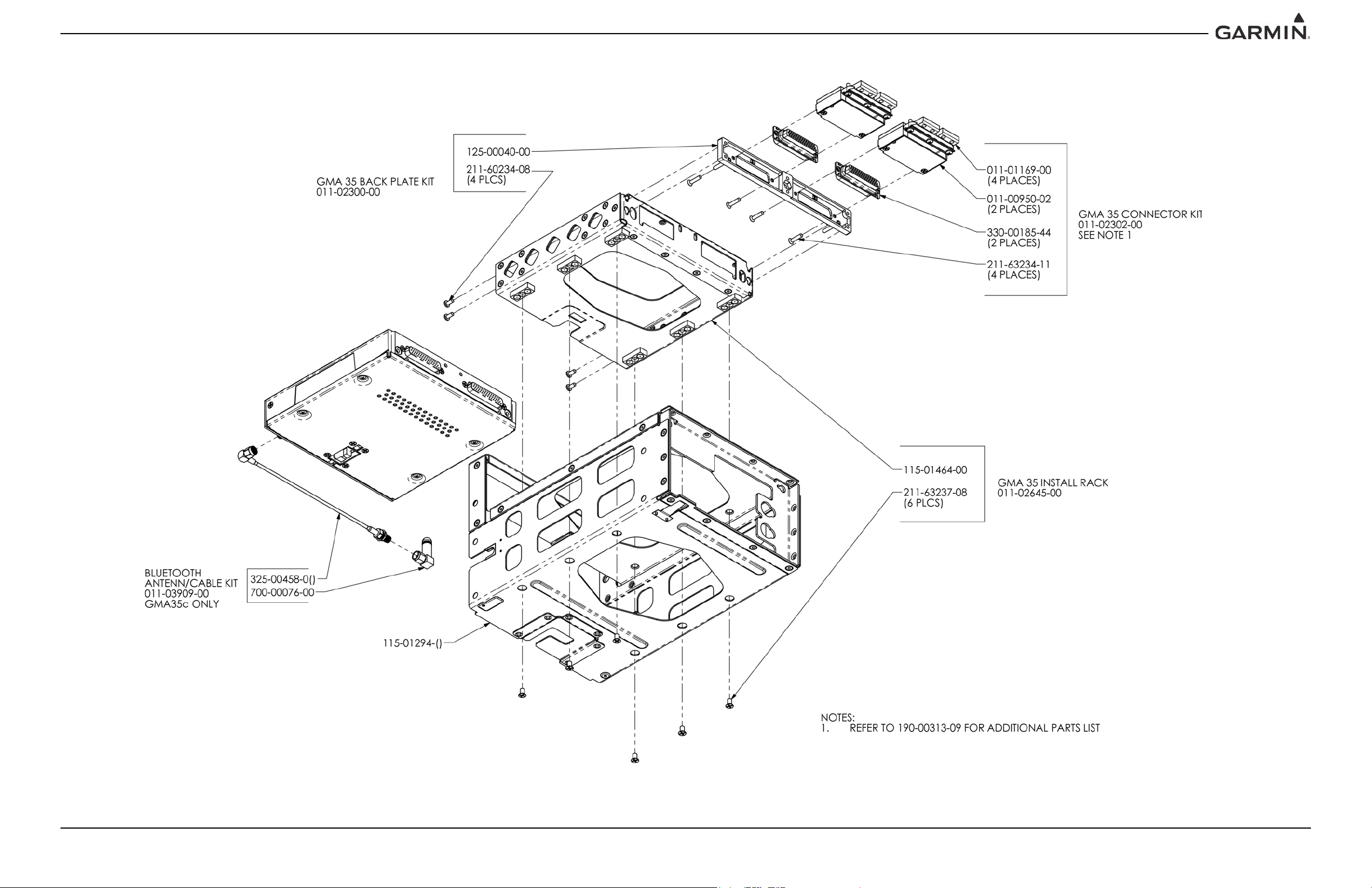
APPENDIX B OUTLINE AND INSTALLATION DRAWINGS
Figure B-2. GMA 35 Connector/Rack Assembly Drawing
190-00858-11 GMA 35/35c Installation Manual
Rev. H Page B-2
Page 49

APPENDIX B OUTLINE AND INSTALLATION DRAWINGS
Figure B-3. GMA 35c Panel Cutout For Bluetooth Antenna Connector
190-00858-11 GMA 35/35c Installation Manual
Rev. H Page B-3
Page 50

APPENDIX C INTERCONNECT DRAWINGS
Figure C-1. Notes
190-00858-11 GMA 35/35c Installation Manual
Rev. H Page C-1
Page 51
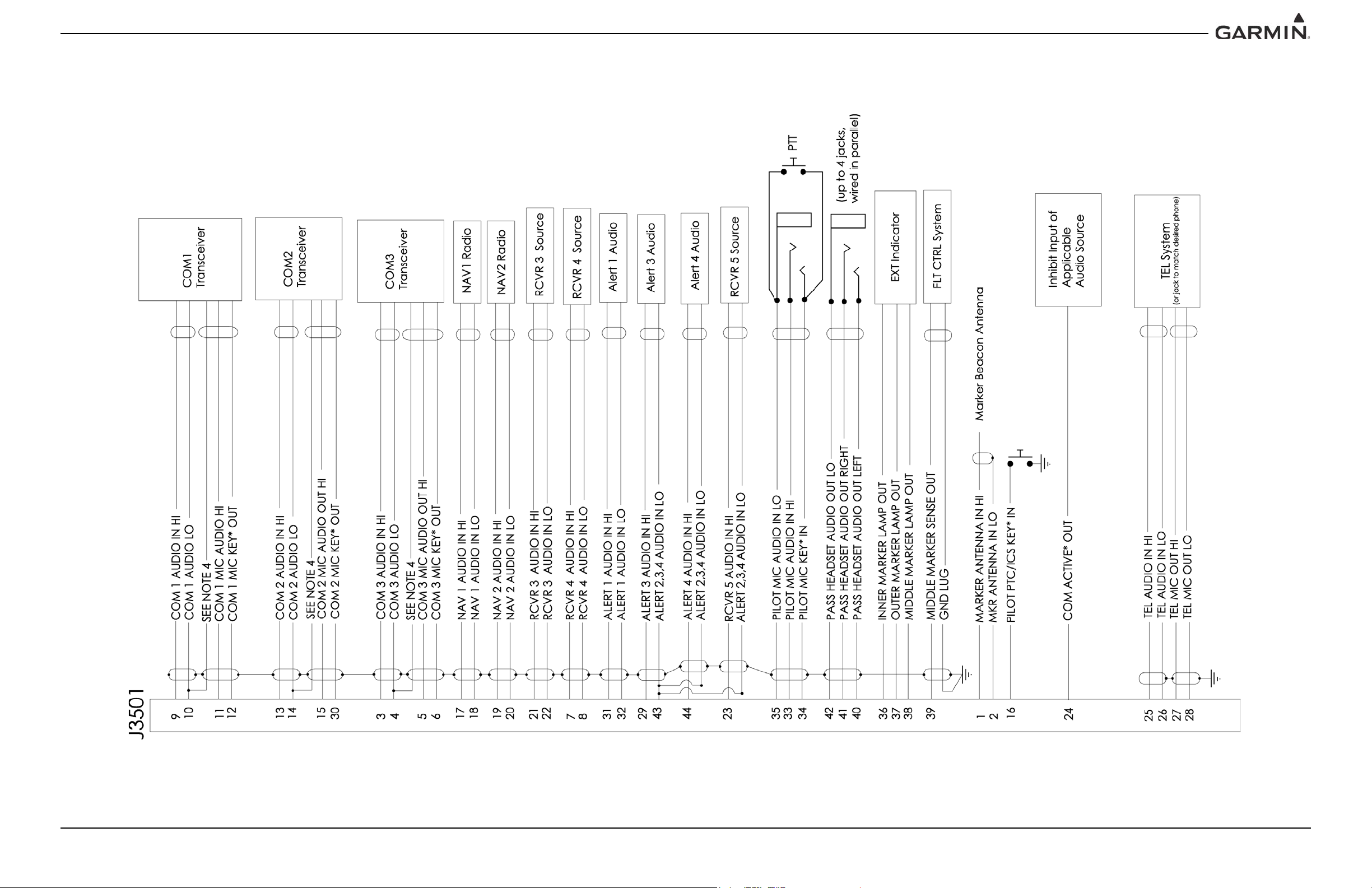
APPENDIX C INTERCONNECT DRAWINGS
Figure C-2. J3501 Interconnects
190-00858-11 GMA 35/35c Installation Manual
Rev. H Page C-2
Page 52
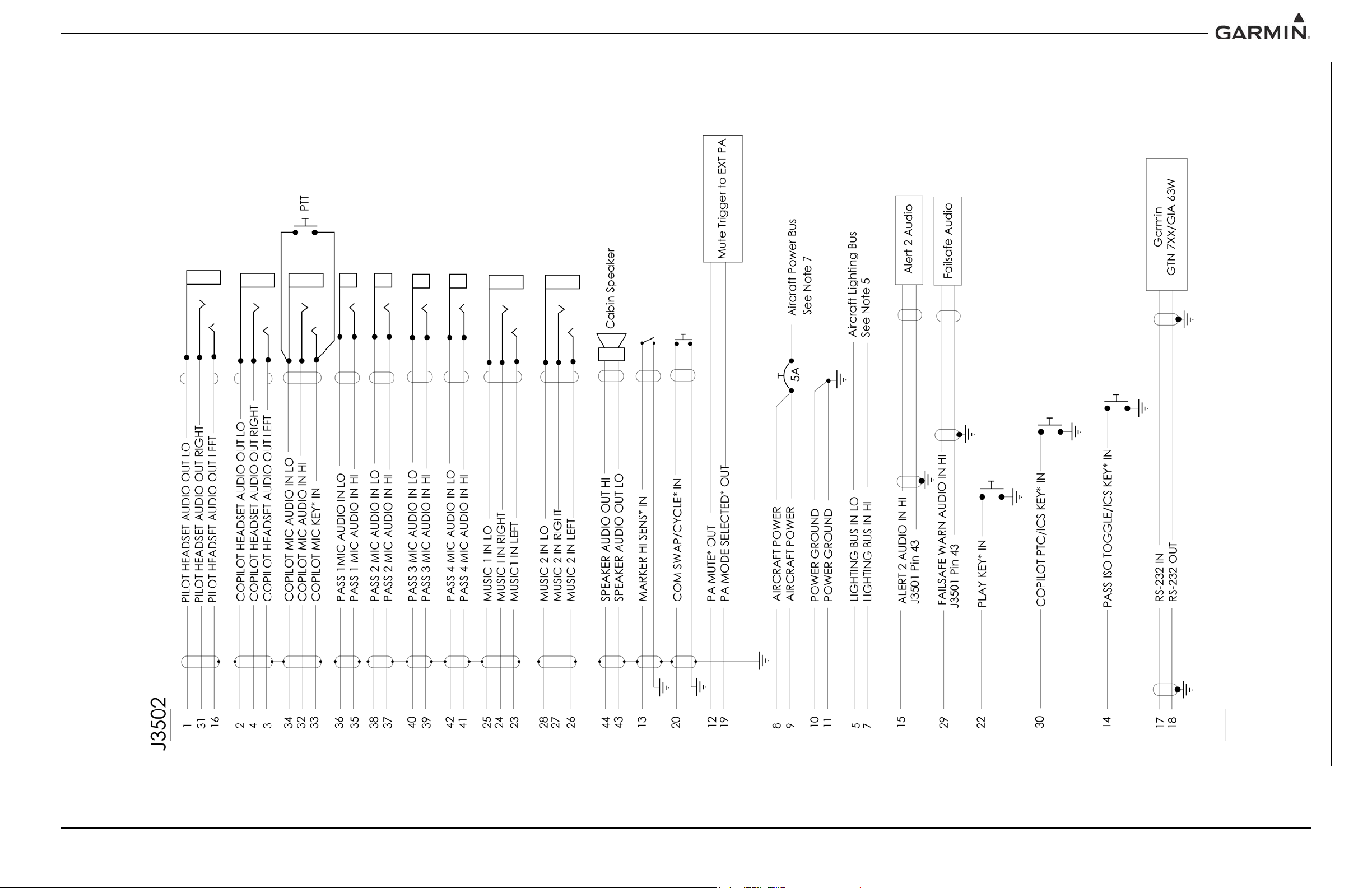
APPENDIX C INTERCONNECT DRAWINGS
Figure C-3. J3502 Interconnects
190-00858-11 GMA 35/35c Installation Manual
Rev. H Page C-3
Page 53

APPENDIX C INTERCONNECT DRAWINGS
Figure C-4. J3501 & J3502 Connector Layout Drawing (Sheet 1 of 2)
190-00858-11 GMA 35/35c Installation Manual
Rev. H Page C-4
Page 54

APPENDIX C INTERCONNECT DRAWINGS
Figure C-5. J3501 & J3502 Connector Layout Drawing (Sheet 2 of 2)
190-00858-11 GMA 35/35c Installation Manual
Rev. H Page C-5
Page 55

Part Information
Item Attribution
Document Review Required: ARR
Moisture Sensitive:
Limited Shelf Life:
Magnetic Sensitive:
GPN: 190-00858-11
Description: GMA35/35c Installation Manual
Part Type: Manuals / Printed Literature
Lifecycle Phase: Production
Rev: H ECO#139773
Item Notes:
Preferred Rating:
ESD Sensitive:
Item Attribution 1 of 1 Item: 190-00858-11 Rev:H ECO#139773 Creation Date: 11-Apr-2016 03:49 PM CST
 Loading...