

Page 1
Fishfi nder 320C
owner’s
manual
and
reference
guide
Page 2

© Copyright 2003 Garmin Ltd. or its subsidiaries
Garmin International, Inc.
1200 East 151st Street, Olathe, KS 66062, U.S.A.
Tel. 913/397.8200 or 800/800.1020 Fax 913/397.8282
Garmin (Europe) Ltd.
Unit 5, The Quadrangle, Abbey Park Industrial Estate, Romsey SO51 9DL, U.K.
Tel. 44/1794.519944 Fax 44/1794.519222
Garmin Corporation
No. 68, Jangshu 2nd Road, Shijr, Taipei County, Taiwan
Tel. 886/2.2642.9199 Fax 886/2.2642.9099
All Rights Reserved. Except as expressly provided herein, no part of this manual may be reproduced, copied, transmitted, disseminated, downloaded or
stored in any storage medium, for any purpose without prior written consent of Garmin. Garmin hereby grants permission to download a single copy of this
manual and of any revision of this manual onto a hard drive or other electronic storage medium to be viewed and to print one copy of this manual or any
revision hereto, provided that such electronic or printed copy of this manual or revision must contain the complete text of this copyright notice and provided
further that any unauthorized commercial distribution of this manual or any revision hereto is strictly prohibited.
Information in this manual is subject to change without notice. Garmin reserves the right to change or improve its products and to make changes in the content without obligation to notify any person or organization of such changes. Visit the Garmin web site (www.garmin.com) for current updates and supplemental information concerning the use and operation of this and other Garmin products.
GARMIN®, See-Thru® and DCG (Depth Control Gain)® are registered trademarks of Garmin Ltd. or its subsidiaries and may not be used without the express
permission of Garmin.
March 2003 Part Number 190-00261-00 Rev. A Printed in Taiwan
Page 3

Preface
Thank you for choosing the Garmin Fishfi nder 320C. This product is designed for easy operation and to
provide years of reliable service.
Please take the time to read this Owner’s Manual, and learn the operation of your new unit. This will
help ensure that you get the most from the Fishfi nder 320C. This manual is broken down into three sections
for your convenience. Section One covers the installation and testing for the
provides detailed references to the features and operations of the
overview of how sonar works and provides information on interpreting the sonar graph.
Product Support
If you encounter a problem, or just have a question, our Product Support Department can be reached
Monday-Friday 8am to 5pm Central Standard Time.
By phone at— 1-800-800-1020 or (913)397-8200
Online at— http://www.garmin.com/contactUs/techSupport.jsp
Check the Garmin Web Site (www.garmin.com) for links to Product Support and Product FAQ’s
Enjoy your new Fishfi nder 320C and once again thank you for choosing Garmin.
Product Registration
Help us better support you by completing our on-line registration today! Have the serial number
of your Fishfi nder 320C Sounder handy and connect to our web site (www.garmin.com). Look for the Product Registration link on the Home page. Also, be sure to record your serial number in the area provided on
page ii of this manual.
Fishfi nder 320C. Section Three gives a basic
Fishfi nder 320C. Section Two
Introduction
Preface and
Registration
NOTE: If you have previously registered a Garmin product purchase, we invite you to re-reg-
)
ister using our NEW on-line system. Many services provided by our new product registration
system are now being automated and re-registering your purchase ensures you the best
possible support from Garmin.
i
Page 4

Introduction
Warranty and
Serial Number
Serial Number
Use this area to record the serial number (8-digit number
located on the bottom of the unit) in case it is lost, stolen, or
needs service. Be sure to keep your original sales receipt in a
safe place or attach a photocopy inside the manual.
Serial Number:
*
*
,
The Fishfi nder 320C Sounder is fastened shut with screws.
Any attempt to open the case to change or modify the unit
in any way will void your warranty and may result in
permanent damage to the equipment.
LIMITED WARRANTY
This Garmin product is warranted to be free from defects in materials or workmanship for one year from
the date of purchase. Within this period, Garmin will at its sole option, repair or replace any components
that fail in normal use. Such repairs or replacement will be made at no charge to the customer for parts or
labor, provided that the customer shall be responsible for any transportation cost. This warranty does not
cover failures due to abuse, misuse, accident or unauthorized alteration or repairs.
THE WARRANTIES AND REMEDIES CONTAINED HEREIN ARE EXCLUSIVE AND IN LIEU OF ALL
OTHER WARRANTIES EXPRESS OR IMPLIED OR STATUTORY, INCLUDING ANY LIABILITY ARISING
UNDER ANY WARRANTY OF MERCHANTABILITY OR FITNESS FOR A PARTICULAR PURPOSE, STATUTORY OR OTHERWISE. THIS WARRANTY GIVES YOU SPECIFIC LEGAL RIGHTS, WHICH MAY VARY
FROM STATE TO STATE.
IN NO EVENT SHALL GARMIN BE LIABLE FOR ANY INCIDENTAL, SPECIAL, INDIRECT OR
CONSEQUENTIAL DAMAGES, WHETHER RESULTING FROM THE USE, MISUSE, OR INABILITY TO
USE THIS PRODUCT OR FROM DEFECTS IN THE PRODUCT. Some states do not allow the exclusion of
incidental or consequential damages, so the above limitations may not apply to you.
Garmin retains the exclusive right to repair or replace the unit or software or offer a full refund of the
purchase price at its sole discretion. SUCH REMEDY SHALL BE YOUR SOLE AND EXCLUSIVE REMEDY
FOR ANY BREACH OF WARRANTY.
To obtain warranty service, contact your local Garmin authorized dealer. Or call Garmin Customer Service at one of the numbers shown below, for shipping instructions and an RMA tracking number. The unit
should be securely packed with the tracking number clearly written on the outside
should then be sent, freight charges prepaid, to any Garmin warranty service station. A copy of the original
sales receipt is required as the proof of purchase for warranty repairs.
Products sold through online auctions are not eligible for rebates or other special offers from Garmin.
Online auction confi rmations are not accepted for warranty verifi cation. To obtain warranty service, an
original or copy of the sales receipt from the original retailer is required. Garmin will not replace missing
components from any package purchased through an online auction.
of the package. The unit
Garmin International, Inc. Garmin (Europe) Ltd.
1200 East 151st Street Unit 4, The Quadrangle, Abbey Park Industrial Estate
Olathe, Kansas 66062, U.S.A. Romsey, SO51 9DL, U.K.
ii
Phone: 913/397.8200 Phone: 44/1794.519944
FAX: 913/397.0836 FAX: 44/1794.519222
Page 5

Software License Agreement
BY USING THE FISHFINDER 320C, YOU AGREE TO BE BOUND BY THE TERMS AND CONDITIONS
OF THE FOLLOWING SOFTWARE LICENSE AGREEMENT. PLEASE READ THIS AGREEMENT CAREFULLY.
Garmin grants you a limited license to use the software embedded in this device (the “Software) in binary
executable form in the normal operation of the product. Title, ownership rights and intellectual property
rights in and to the Software remain in Garmin.
You acknowledge that the Software is the property of Garmin and is protected under the United States of
America copyright laws and international copyright treaties. You further acknowledge that the structure,
organization and code of the Software are valuable trade secrets of Garmin and that the Software in source
code form remains a valuable trade secret of Garmin. You agree not to decompile, disassemble, modify,
reverse assemble, reverse engineer or reduce to human readable form the Software of any part thereof or
create any derivative works based on the Software. You agree not to export or re-export the Software to any
country in violation of the export control laws of the United States of America.
,
WARNING: This product, its packaging, and its components contain chemicals known to the State of
California to cause cancer, birth defects, or reproductive harm. This Notice is being provided in accordance
with California’s Proposition 65. If you have any questions or would like additional information, please refer
to our web site at http://www.garmin.com/prop65.
Introduction
Software License Agreement
iii
Page 6

Introduction
Packing List
Before installing and getting started with your unit, please check to see that your package includes the
following items. The package part number can be found on the outside of the box. If any parts are miss-
ing, please contact your Garmin dealer immediately.
Standard Package (010-00289-00 w/o transducer):
• Fishfi nder 320C Unit • Surface-Mount Bracket and Knobs • Power/Data Cable • Owner’s Manual
• Self-Adhesive Quick Reference Guide • Protective Cover • Flush-Mount Hardware Kit
Optional Package (010-00289-01) includes Standard Package, plus:
• Dual Frequency (200/50kHz, 10/40°) Plastic Transom Mount Transducer with Depth and Temp
• Separate Speed Sensor
)
For the most recent list of available accessories for your
unit, current user manuals and software updates, visit our
web site at www.garmin.com.
iv
Optional Package (010-00289-02) includes Standard Package, plus:
• Single Frequency (200kHz, 20°) Plastic Transom Mount Transducer with Depth and Temp
• Separate Speed Sensor
Optional Accessories:
• US A/C PC Adapter • EURO A/C PC Adapter • Cigarette Lighter Adapter • 2nd Mounting Station
• 10 ft. Transducer Extension cable • 20 ft. Transducer Extension cable • Temperature probe
• Speed sensor • Temp & Speed only sensor, plastic, thru-hull mount
Optional Transducers:
Included in the Optional Packages are transom mount transducers and separate speed sensors. These
transducers provides good all-around performance. For a list of optional transducers, see page v.
Page 7

Transducers
The transducer acts as the eyes and ears of your new sonar. Proper transducer selection and installation
are important to the operation of your unit. The transducer transmits sound waves toward the bottom in a
cone shape. The larger the cone angle the larger the coverage area at a given depth. While it is good to see as
large of an area as possible, it is best to select a transducer that suits the water that you are on.
A wide cone angle transducer works best in shallower water. The wide cone angle provides a large coverage or viewing area, but at a decreased bottom resolution. In deeper water this can result in a large dead
zone where fish cannot be seen.
A narrow cone angle transducer is better suited to deep water installations. The narrow cone angle provides a smaller coverage or viewing area (compared to a wide cone angle transducer at the same depth) with
improved bottom resolution and a smaller dead zone.
A variety of optional transducers are available from your local dealer or direct from Garmin.
• 200/50kHz, 12/45°, plastic, transom mount, depth, temp
• 200/50kHz, 12/45°, plastic, transom mount, depth, temp, speed
• 200/50kHz, 12/45°, bronze, thru-hull mount, depth
• 200/50kHz, 12/45°, bronze, thru-hull mount, depth, temp, speed
• 200/50kHz, 12/45°, bronze, thru-hull mount/long stem, depth, temp, speed
• 200/50kHz, 12/45°, plastic, thru-hull mount, depth
• 200/50kHz, 12/45°, plastic, adjustable. in-hull mount
• 200kHz, 14°, plastic, transom mount, depth
• 200kHz, 14°, plastic, transom mount, depth, temp
• 200kHz, 14°, plastic, transom mount, depth, temp, speed
• 200kHz, 8°, plastic, transom mount, depth, temp
• 200kHz, 8°, plastic, transom mount, depth, temp, speed
• 200kHz, 12°, bronze, thru-hull mount, depth
• 200kHz, 12°, bronze, thru-hull mount, depth, temp
• 200kHz, 9°, bronze, thru-hull mount, depth, temp, speed
• 200kHz, 12°, plastic, thru-hull mount, depth
• 200kHz, 12°, plastic, thru-hull mount, depth, temp
• 200kHz, 14°, plastic, in-hull mount, depth
• 200kHz, 14°, plastic, trolling motor mount, depth, temp
Introduction
Selecting a Transducer
Wide cone angle
Narrow cone angle
dead zone
fish not seen
X
X
v
Page 8

Introduction
Table of Contents
Introduction . . . . . . . . . . . . . . . . . . . . . . . . . . . i-vi
Preface and Registration . . . . . . . . . . . . . . . . . . i
Warranty . . . . . . . . . . . . . . . . . . . . . . . . . . . . .ii
Software License Agreement . . . . . . . . . . . . . . iii
Packing List . . . . . . . . . . . . . . . . . . . . . . . . . . iv
Selecting a Transducer . . . . . . . . . . . . . . . . . . . v
Table of Contents . . . . . . . . . . . . . . . . . . . . . . vi
Section One: Installation . . . . . . . . . . . . . . . . . 1-7
Unit Installation . . . . . . . . . . . . . . . . . . . . . . . .1
Wiring and Interfacing . . . . . . . . . . . . . . . . . . .3
Mounting the Transducer . . . . . . . . . . . . . . . . .5
Testing the Installation . . . . . . . . . . . . . . . . . . .7
Section Two: Unit Operation . . . . . . . . . . . . . 8-20
Keypad Usage . . . . . . . . . . . . . . . . . . . . . . . . . . 8
Sonar Page . . . . . . . . . . . . . . . . . . . . . . . . . . . .9
Using the Adjustment Menu . . . . . . . . . . . . . . 10
Adjustment Menu Options . . . . . . . . . . . . . . .10
Range . . . . . . . . . . . . . . . . . . . . . . . . . . . .10
Zoom . . . . . . . . . . . . . . . . . . . . . . . . . . . .10
View/Span . . . . . . . . . . . . . . . . . . . . . . . . 11
Gain . . . . . . . . . . . . . . . . . . . . . . . . . . . . .11
Target Level . . . . . . . . . . . . . . . . . . . . . . . 11
Whiteline . . . . . . . . . . . . . . . . . . . . . . . . .12
Frequency . . . . . . . . . . . . . . . . . . . . . . . . .12
vi
Depth Line . . . . . . . . . . . . . . . . . . . . . . . .12
Noise Reject . . . . . . . . . . . . . . . . . . . . . . .12
Scroll . . . . . . . . . . . . . . . . . . . . . . . . . . . .12
Size Split . . . . . . . . . . . . . . . . . . . . . . . . . .12
Using the PAUSE Key . . . . . . . . . . . . . . . . . .13
Using the DATA Key . . . . . . . . . . . . . . . . . . .14
Main Menu . . . . . . . . . . . . . . . . . . . . . . . . . . . 15
Graph Tab . . . . . . . . . . . . . . . . . . . . . . . . . . .15
Fish Symbols . . . . . . . . . . . . . . . . . . . . . .15
Scale . . . . . . . . . . . . . . . . . . . . . . . . . . . . . 15
Custom Range . . . . . . . . . . . . . . . . . . . . . 16
Background Color . . . . . . . . . . . . . . . . . .16
Number Size . . . . . . . . . . . . . . . . . . . . . . .16
Temperature and Water Speed . . . . . . . . .16
Tools Tab . . . . . . . . . . . . . . . . . . . . . . . . . . . .16
Flasher . . . . . . . . . . . . . . . . . . . . . . . . . . .16
Color Bar . . . . . . . . . . . . . . . . . . . . . . . . . 16
Temperature Graph . . . . . . . . . . . . . . . . .16
Temp Tab . . . . . . . . . . . . . . . . . . . . . . . . . . . .16
Temperature Scale . . . . . . . . . . . . . . . . . .16
Time Duration . . . . . . . . . . . . . . . . . . . . .16
Reset Auto Scale . . . . . . . . . . . . . . . . . . . .16
Alarms Tab . . . . . . . . . . . . . . . . . . . . . . . . . . .17
Fish Alarm . . . . . . . . . . . . . . . . . . . . . . . .17
Shallow/Deep Water Alarms . . . . . . . . . . .17
Drift Alarm . . . . . . . . . . . . . . . . . . . . . . . .17
Water Temperature Alarm . . . . . . . . . . . . .17
Battery Alarm . . . . . . . . . . . . . . . . . . . . . .17
Timer Alarm . . . . . . . . . . . . . . . . . . . . . . .17
System Tab . . . . . . . . . . . . . . . . . . . . . . . . . . .18
Beeper . . . . . . . . . . . . . . . . . . . . . . . . . . .18
Language . . . . . . . . . . . . . . . . . . . . . . . . .18
Simulator . . . . . . . . . . . . . . . . . . . . . . . . .18
NMEA Input/Output . . . . . . . . . . . . . . . .18
Factory Settings . . . . . . . . . . . . . . . . . . . .18
Software Version . . . . . . . . . . . . . . . . . . . .18
Reset Odometer . . . . . . . . . . . . . . . . . . . . 18
Units Tab . . . . . . . . . . . . . . . . . . . . . . . . . . . . 18
Depth . . . . . . . . . . . . . . . . . . . . . . . . . . . . 18
Temperature . . . . . . . . . . . . . . . . . . . . . . .18
Distance and Speed . . . . . . . . . . . . . . . . .18
Position Format . . . . . . . . . . . . . . . . . . . .18
Heading . . . . . . . . . . . . . . . . . . . . . . . . . .19
Sonar Tab . . . . . . . . . . . . . . . . . . . . . . . . . . . .19
Water Type . . . . . . . . . . . . . . . . . . . . . . . .19
Depth Number . . . . . . . . . . . . . . . . . . . . . 19
Automatic Scroll Speed Limit . . . . . . . . . .19
Keel Offset . . . . . . . . . . . . . . . . . . . . . . . . 19
Transducer Type . . . . . . . . . . . . . . . . . . . .19
Calibrate Water Speed . . . . . . . . . . . . . . .19
Time Tab . . . . . . . . . . . . . . . . . . . . . . . . . . . .20
Time Format . . . . . . . . . . . . . . . . . . . . . . . 20
Time Zone . . . . . . . . . . . . . . . . . . . . . . . .20
Daylight Saving Time . . . . . . . . . . . . . . . . 20
Current Time and Date . . . . . . . . . . . . . . .20
Section Three: On the Water . . . . . . . . . . . . 21-24
Understanding Sonar . . . . . . . . . . . . . . . . . . .21
Transducer Coverage . . . . . . . . . . . . . . . . . . .22
Understanding the Graph . . . . . . . . . . . . . . . .23
Whiteline and Thermoclines . . . . . . . . . . . . . 24
Appendices . . . . . . . . . . . . . . . . . . . . . . . . . 25-28
Appendix A: Specifi cations and Cleaning . . . .25
Appendix B: Messages and Alarms . . . . . . . . .26
Appendix C: Index . . . . . . . . . . . . . . . . . . . . . 27
Page 9
Installing the Fishfi nder 320C
The Fishfi nder 320C must be properly installed according to the following instructions to get the best
possible performance. To complete the installation, you’ll need the appropriate fasteners and tools. Check
that all cables will reach the unit mounting location and also take time to read through these instructions
prior to installation. Be sure to always wear safety goggles and a dust mask when drilling, cutting or sanding. When in doubt, seek professional assistance.
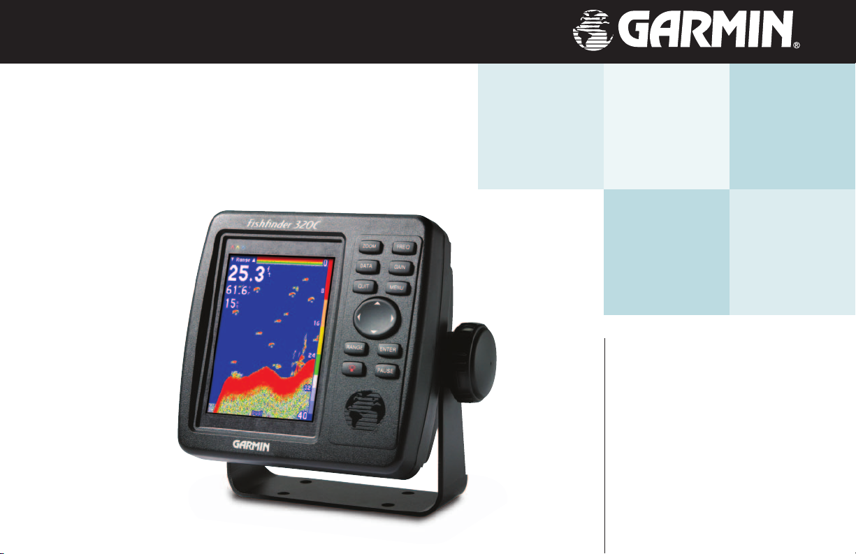
Surface Mounting the Fishfi nder 320C Unit
The Fishfi nder 320C’s compact, waterproof case is suitable for mounting in exposed locations or at the
nav station. The unit comes with a surface-mount bracket that can be used for console or overhead mounting. When choosing a location for the display unit, make sure you consider the following conditions:
• There should be at least a 3” (8 cm) clearance behind the case to allow connection of the transducer
and power/data cables.
• The mounting surface should be heavy enough to support the unit and protect it from excessive
vibration and shock.
NOTE: The temperature range for the Fishfi nder 320C is 5°F to 158°F (-15°C to 70°C).
,
Extended exposure to temperatures exceeding this range (in storage or operating conditions) may cause failure of the LCD screen. This type of failure and related consequences are
NOT covered by the manufacturer’s limited warranty.
To surface mount the Fishfi nder 320C display:
1. Place the mounting bracket in the desired location.
2. Mark and drill the four mounting holes for the fastener you are using.
3. Fasten the bracket to the surface using the appropriate fasteners.
4. Insert the Fishfi nder 320C into the mounting bracket. The bracket is designed for a tight fi t to provide
additional support when swiveling the unit.
5. Screw the two mounting knobs through the bracket and into the display case.
6. Connect the power/data and transducer cables to the back of the unit, making sure the locking rings are
fully tightened on both connectors.
Installation
Unit Installation
OK
The Mounting Bracket is designed to be secured using a
fl at head screw. If you use a screw with a countersunk
head, you risk damaging the Mounting Bracket.
1
Page 10

Installation
Unit Installation
WasherHex Nuts
Studs
Flush Mounting the Fishfi nder 320C Unit
The Fishfi nder 320C can be fl ush mounted on a fl at panel. When fl ush mounting the Fishfi nder 320C,
be sure to choose an appropriately sized location for the unit. Check that all cables will reach the unit
mounting location before beginning installation. Use the Flush Mount Template provided in the box to
determine a location. Be sure to always wear safety goggles and a dust mask when drilling, cutting or sanding. Included Mounting Hardware: 4 - 3mm Studs, 4 - Flat Washers, 8 - 3mm Hex Nuts
To fl ush mount the Fishfi nder 320C:
1. Trim the Flush Mount Template and tape in the desired location.
2. Using a Center Punch, indent the center of each Mounting Hole location.
3. Using an 1/8” (3mm) drill bit, drill the four Mounting Holes.
4. Using a 3/8” (6mm) drill bit, drill a hole for a location to begin cutting the mounting surface.
5. Using the Jig Saw, cut the mounting surface along the inside of the dashed line indicated on the
template. Be very careful when cutting this hole, there is only a small amount of clearance
between the unit and the Mounting Holes. It may be prudent to cut slightly inside the indicated
line and then sand or fi le the panel as needed to obtain the best fi t.
6. Install the four Mounting Studs into unit by screwing the shorter section in to the back of the unit. Use a
1/16” (2mm) Allen Wrench to tighten the Mounting Studs until the stop contacts the case. Be careful not
to overtighten as this may damage the Mounting Stud! The studs have a reusable thread-locking patch
pre-applied from the factory.
7. Place the unit in position in the cut out in the mounting surface.
8. Place washers over the Mounting Studs, then thread on one Hex Nut per Mounting Stud. Tighten all four
until the unit is snug against the mounting surface. Install and tighten the second Hex Nut on all four
Mounting Studs to lock the fi rst one in place.
2
Page 11
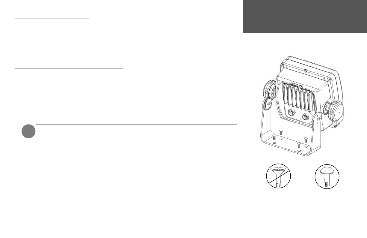
Connecting the Power/Data Cable
The power/data cable connects the Fishfi nder 320C to a 10-35 volt DC system and provides interface
capabilities for connecting external devices. The color code in the diagram (pg. 4) indicates the appropriate
harness connections. Replacement fuse is a AGC/3AG - 2 Amp fuse. If it is necessary to extend the power/
data wires, use a wire of comparable size and keep your extension as short as possible.
If your boat has an electrical system, it may be possible to wire the unit directly to an unused holder on
your current fuse block. If you are using the boat’s fuse block, remove the in-line fuse holder supplied with
the unit. If your boat does not have a fuse block, the unit can be wired directly to the battery. Make sure the
2-Amp in-line fuse supplied with the unit is installed if connecting the unit direct to the battery.
Installing the Wiring Harness (Basic):
1. Determine the polarity of the fuse holder using a Test Light or Volt Meter.
2. Install the Red (+) wire on the Positive Fuse Holder Terminal.
3. Install the Black (-) wire on the Negative Fuse Holder Terminal.
4. Install a 2 amp fuse in the Fuse Holder.
Install 2-Amp
Fuse
The Fishfi nder 320C can be connected to another piece of NMEA compatible electronic equipment,
such as a Garmin GPS (Global Positioning System). If equipped with a capable transducer, the Fishfi nder
320C can send depth, temperature, and speed information. It can also mark a location (pg. 13) that could
be displayed on another device and can accept GPS navigational data (pg. 14), such as position, time,
course, distance, etc. Refer to the wiring diagram on the following page for interfacing the Fishfi nder 320C
with other devices.
Installing the Wiring Harness to a GPS:
1. Follow steps 1-4 of the above wiring harness installation. For Garmin units, the Ground (black) wires
from both devices must be attached together or on the same fuse terminal for data ground. Refer to the
wiring diagram of your GPS unit for wire identifi cation.
2. Connect the Blue (Data Out) wire from the Fishfi nder to the Data IN wire on the GPS harness.
3. Connect the Brown (Data In) wire from the Fishfi nder to the Data OUT wire on the GPS harness.
4. Set the Fishfi nder 320C NMEA Input/Output to ‘On’ (pg. 18). For Garmin GPS units, set the
communications interface to NMEA/NMEA, NMEA In/NMEA Out or NMEA.
Boat Ground
Installation
Wiring and Interfacing
To 10-35 Volt Boat Supply
+
2A
-
Black Wire
To Fishfi nder 320C
Red Wire
3
Page 12
Installation
Wiring and Interfacing
You can download a copy of Garmin's proprietary communication protocol document from
the Help and Support section of our web site at
www.garmin.com.
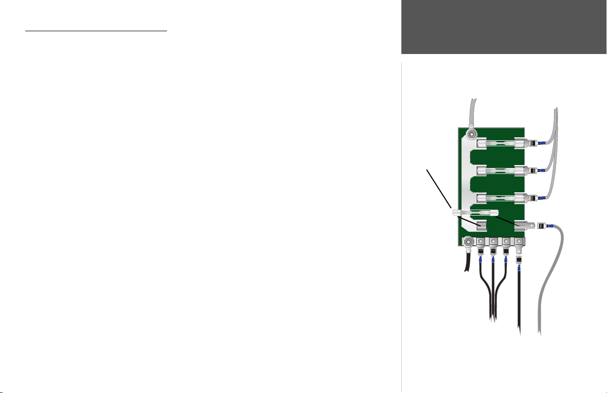
PIN 1 (red) 10-35 VDC
PIN 2 (black) Ground (Power and Data)
(Cable View)
4
3
5
2
6
1
7
PIN 3 (blue) Port 1 Data OUT
PIN 4 (brown) Port 1 Data IN
PIN 5 (white) Port 2 Data IN (N/C)
PIN 6 (green) Port 2 Data OUT
PIN 7 (yellow) Alarm Low
Note: During a typical installation, only the Red and
Black wires are used. The other wires do not have to
be connected for normal operation of the unit.
Alarm Relay
100ma max
coil current
Power
10-35 volts DC
RXD +
GPS/NMEA
Device
TXD +
and RXD -
NMEA Device
RXD +
Complete information concern-
ing National Marine Electronics
Association (NMEA) format and
sentences is available for purchase
from NMEA at:
NMEA
Seven Riggs Avenue
Severna Park, MD 21146
U.S.A.
410-975-9425
410-975-9450 FAX
www.nmea.org
Interfacing
The Fishfi nder 320C allows for NMEA 0183, Version 2.3 input/output with a compatible GPS or
navigation device. NMEA Input/Output must be set to ‘On’ to send/receive data. (see pg. 18). For additional
information on using your Fishfi nder 320C with NMEA devices, see pages 3, 13-14, and 18.
The following are the sentences for NMEA 0183, version 2.3:
Input — GPBOD, GPBWC (only used if RMB not present), GPGGA, GPGLL (only used if GGA not present),
GPRMB, GPRMC, GPXTE (only used if RMB not present)
Output — SDDBT, SDDPT, SDMTW, SDVHW, SDWPL* (only if a waypoint is “marked” in Pointer Mode)
*Garmin GPS units will accept the SDWPL (WPL) NMEA sentence and create a waypoint (saved location) at that position (see pg.
13). For compatibility with other brands of GPS or NMEA capable navigation devices, check with that manufacturer to see if their unit
4
accepts/stores NMEA 0183 SDWPL sentences/waypoints. The Fishfi nder 320C does not store the actual waypoint. Only the receiving
device, if capable, will store the waypoint.
Page 13

Proper transducer installation is key to getting the best performance from your new unit. If the transducer lead is too short, extension cables are available from your Garmin dealer. Coil and secure any excess
cable. DO NOT cut the transducer lead or any part of the transducer cable, as this will void your warranty.
The cable cannot be spliced and connected to any existing (Garmin or non-Garmin) transducer cables.
Following are some tips and basic installation instructions for some popular transducers. Detailed
installation instructions are provided in the transducer kits. Some transducers may need to be
installed by a professional marine installer.
Transom Mount Installation
Transom Mount Transducer (depth/temp)
Apply marine sealant to all
screw threads to prevent water
from seeping into the transom.
OK
Mount the transducer parallel with the bottom.
USS Jayhawk
DO NOT mount the transducer behind strakes,
struts, fi ttings, water intake or discharge ports,
or anything that creates air bubbles or causes the
water to become turbulent. It is important that the
transducer be in clean (non-turbulent) water for
optimal performance.
Mount the transducer cable cover
well above the waterline.
Transducer should extend 1/8" below
fiberglass hull or 3/8" below aluminum hull
Make sure that the transducer is
below water level when the boat
is on plane at high speed
Do not mount transducer directly in the
path of the prop. The transducer can cause
cavitation that may degrade the boat's performance
and damage the prop.
,
Installation
Mounting the Transducer
To Unit
Speed Temp Transducer
Connecting a Transducer to Multiple Sensors
5
Page 14

Installation
Mounting the Transducer
PVC Pipe
or a Can
Strip Caulk
or RTV Sealer
Weight transducer
to hold it in place
Fill Pipe or Can
with water or a
light mineral oil
To avoid drilling a hole to mount a thru-hull transducer, a transducer may be secured with epoxy inside
a boat (“shoot-thru-hull” installation). This type of installation can provide better noise reduction and allow
you to use a higher gain setting. For a transducer to be mounted inside the hull (shoot-thru, not thru-hull),
the boat must be fi berglass, with no core. Contact your boat manufacturer if you are unsure. Professional
installation may be necessary. Be sure to always wear a dust mask and safety goggles.
Shoot-Thru-Hull Installation
Some transducers are specifi cally designed to be mounted inside a fi berglass hull. The standard plastic
transom mount transducer can also be mounted in this fashion using this method. If using a temperature
sensing transducer, the temperature displayed will refl ect the hull temperature.
Selecting a location:
1. The location has to be solid fi berglass, devoid of any air bubbles, laminates, fi llers or dead air space. The
location needs to be in an area of clean water at all speeds. Do not place the transducer over any strakes
or behind any obstruction on the hull that would create turbulence at speed.
NOTE: Many modern hulls have a prelocated pocket for shoot-thru-hull transducer
)
installation. If you are unsure if your hull is equipped with a pre-located pocket,
contact your hull manufacturer.
Hull Surface
6
Testing the Location
Testing the location:
1. Fabricate a test device from a section of PVC pipe or a can, as shown in the side bar.
2. Temporarily seal the test device to the hull with caulking or RTV sealer, and fi ll with water or light
mineral oil.
3. Place the transducer in the water, pointed directly at the bottom and weight it down. Set unit for optimum performance. If the sonar performance is signifi cantly degraded, another location will need to be
tested.
Permanently installing the transducer:
1. Lightly sand the surface of the hull and face of the transducer with 400 grit wet or dry sandpaper.
2. Build a dam using strip caulk about 1/4” tall. Pour about 1/8” of two part, slow cure epoxy in the dam.
3. Place the transducer in the epoxy, turning the transducer to work out any air bubbles.
4. Weight the transducer in place and allow to cure for 24 hours.
Page 15

Testing the Installation
While it is possible to perform some checks with the boat trailered, the boat should be in the water to
properly test the sonar portion of the installation.
Press the POWER/BACKLIGHT key (see pg. 8) and the Fishfi nder 320C should power on. If the unit
fails to power on, verify that the wiring adapter is seated properly in the back of the unit, the Red and Black
wires are connected to the correct polarity, and that the 2-Amp fuse is installed and not blown. If the unit is
connected to a power supply that exceeds 35v DC, a “Battery Voltage High” warning will be displayed and
the unit will turn off. If the unit does not detect a transducer, it will automatically enter Simulator Mode.
When the unit detects a transducer on initial power up, a “Please set up transducer” message will
appear. Press the ENTER key (see pg. 8) to select the transducer type. Highlight your transducer type with
the ARROW KEYPAD and press ENTER. Press QUIT to return to the Sonar display.
Since water is necessary to carry the sounder’s sonar signal, the transducer must be in the water to work
properly. It is not possible to get a depth/distance reading when out of the water. As the unit powers on, it
should immediately start showing the bottom. Verify that the unit is not in the simulator mode. If the unit
is in the simulator mode, make sure that the transducer is connected properly to the unit. When you place
your boat in the water CHECK FOR LEAKS around any screw holes that have been added below the water
line. DO NOT leave your boat in the water for an extended period of time without checking for leaks.
Begin testing the installation at a slow speed. If the sonar appears to be working properly, gradually
increase the boat’s speed while observing the sonar’s operation. If the sonar signal suddenly is lost or the
bottom return is severely degraded, note the speed at which this occurs. Return the boat to the speed the
signal was lost. Make moderate turns in both directions and see if the signal improves. If the signal strength
improves while turning, adjust the transducer so that it extends another 1/8" below the transom of the boat.
It may take several adjustments to eliminate the degradation. If the signal does not improve, it may be necessary to move the transducer to a different location.
Installation
Testing the Installation
NOTE: When adjusting the depth of the transducer, make the adjustments in small incre-
)
ments. Placing the transducer too deep can adversely affect the boat’s performance and put
the transducer at greater risk of striking underwater objects.
7
Page 16

Unit Operation
Keypad Usage
ZOOM FREQ
DATA
QUIT
RANGE
GAIN
MENU
ENTER
PAUSE
)
NOTE: Always press and release a key to perform
its primary function. Pressing and holding a key will
activate its secondary function (if available).
8
Using the Keypad
ZOOM Key— displays the Zoom adjustment control. Pressing Up/Down on the ARROW KEYPAD will
select the desired zoom level.
FREQ Key— displays the Frequency adjustment control. Pressing Up/Down on the ARROW KEYPAD will
select the desired sonar frequency.
DATA Key— toggles the data fi eld in the upper left of the Sonar Page between the Basic and Advanced
displays. When held for more than 2 seconds, enters Advanced data setup.
GAIN Key— displays the Gain adjustment control. Pressing Up/Down on the ARROW KEYPAD will select
the desired gain setting.
QUIT Key— exits the current menu or confi guration option. Returns the display to the previous page and,
when entering data, restores the previous data (cancels data entry).
MENU Key— from the sonar screen, displays the Adjustment Menu. Press again to access the Main Menu
for unit confi guration.
ARROW KEYPAD— used to select (highlight) menu options and enter data. Also controls movement of the
cursor when paused in Pointer mode. Allows direct control of Sonar Page Adjustments.
RANGE Key— displays the Range adjustment control. Pressing Up/Down on the ARROW KEYPAD will
select the desired setting.
ENTER Key— selects a highlighted menu option. When entering data, it allows you to initiate entry and
then accept the selected value(s). When paused in Pointer mode, will create a waypoint at the Pointer position (if equipped with compatible NMEA GPS).
POWER/BACKLIGHT Key— press and hold to turn the unit on and off. While the unit is on, pressing and
releasing will display the backlight control. Multiple presses of the POWER/BACKLIGHT key will toggle
the unit’s backlight between maximum, user-set, and minimum backlight brightness levels.
PAUSE Key— pauses the scrolling sonar display. When held for more than 2 seconds, enters Pointer mode.
Use the ARROW KEYPAD to move the cursor around the display to examine the depth of specifi c items
in greater detail. If the Fishfi nder 320C is interfaced with a Garmin GPS or compatible NMEA navigation
device (pgs. 3-4), pressing the ENTER key in this state will send a WPL sentence to that device (if the cur-
rent position is known) creating a waypoint at that position. See pages 13 for more information.
Page 17

Sonar Page
The Sonar Page is where your Fishfi nder 320C becomes a powerful fi shfi nder/fl asher. If the unit does
not detect a transducer, a “Sonar Turned Off” message will appear across the Sonar Page. If in Simulator
mode, a ‘Running Simulator’ message will appear after 2 minutes of inactivity.
The top left of the screen contains numbers or data fi elds, such as Depth, Water Speed and Water Temp
(see pg. 14), while the currently selected Adjustment (see pg. 10) option will appear in the upper left of
the display. The middle of the page contains a right-to-left moving sonar image of the water beneath your
boat. (Note: Items appear as they pass under your transducer. Those items on the right side of the screen are
closer to you than those on the left.) Along the right side of the screen is an adjustable scale which refl ects
Current
Adjustment
Option
Numbers
the depth of the area being displayed.
The sonar display may also be set to show a split screen view of a zoomed portion of the sonar, bottom
lock (display scaled from the bottom up), or a combination of these options (see pg. 11). For example, you
Bottom
may choose to show dual frequency at a 2X zoom (Dual 2X) on one half and normal range dual frequency
(Dual) returns on the other half. The current display mode will be displayed at the bottom of each sonar
display.
Sonar returns will show as red (strongest), then oranges (strong), yellows (medium), greens (weaker)
and blues (weakest). The ‘ Fish Symbols’ option (see page 15) allows you to view the actual sonar data, a fi sh
symbol or a combination of both. ‘Fish Symbols’ will appear as green. When the unit is set to ‘Dual’ (see
page 12), the appearance of the fi sh symbols (and simulated fi sh returns) will change. Fish symbols from the
narrower beam (200kHz) will be solid (or narrow returns), but the returns from the wider beam (50kHz)
will be hollow (or wide returns). Simulated fi sh icons are displayed in three different sizes. Actual fi sh
returns may not always appear as perfect arches, due to the speed, fi sh orientation, and/or other conditions.
Narrow beam
returns
More on understanding the sonar may be found on pages 21-24.
Fish Symbol
Unit Operation
Describing the Display
Depth
Scale
Fish Arches
(Simulated)
Flasher
Thermocline
Wide beam
returns
Frequency
mode
9
Page 18

Unit Operation
Adjustment Menu Options
Current
adjustment
setting
‘Normal’
setting
area
Adjustment Menu options
Current option
Using the Adjustment Menu
The Adjustment Menu allows direct access to the settings and features most commonly used on the
Sonar Page. There are 10 main adjustment options available: Range, Zoom, View, Gain, Target Level,
Whiteline, Frequency, Depth Line, Noise Reject, and Scroll. All adjustments may be made by using the
ARROW KEYPAD and ENTER key. The currently selected option will appear in the upper left of the
display with an up and down arrow on each side of the name.
To change an Adjustment Menu setting:
1. Press the MENU key to bring up a list of all options and their current settings. The adjustment window
will automatically time-out and disappear when idle for 20 seconds or you may press QUIT to exit. Highlight the desired option to change and press ENTER to bring up the Adjustment window. Alternately,
press the dedicated ZOOM, FREQ, GAIN or RANGE key to adjust the desired option.
2. With the ARROW KEYPAD, move UP or DOWN and place the setting bar (or pointer) at the desired per-
centage (Off, 1-100%), setting or range. When changing most adjustments, an open space will appear
on the scale to show where the of ‘Normal’ or default setting would appear. Once set to ‘Normal’, the
setting bar will be replaced by the word ‘Normal’.
3. Press ENTER or QUIT to accept the new setting and return to the sonar graph.
For users accustomed to other Garmin sonar products, the current adjustment will appear in the upper
left corner. For fast adjustment from the Sonar Page, press LEFT or RIGHT on the ARROW KEYPAD to
scroll through the options, then press UP or DOWN on the ARROW KEYPAD to immediately change the
current option or the ENTER key to review the current setting before making changes.
Adjustment
window
Pointer
10
Adjustment Options
The Adjustment Menu allows direct access to the settings and features most commonly used. These
available adjustments are:
• Range — sets the display depth range used for viewing. The unit can be set to automatically track the
bottom or set to a user-specifi ed depth range (see “Custom Range” pg. 16).
• Zoom — used to quickly select a display zoom scale or to split the display. When a scale other than
‘No Zoom’ is selected, the Adjustment Menu will display a new selection labeled View or Span.
Page 19

The Zoom function is divided into six display levels:
2X Split –– Shows two reduced-size sonar pictures at the same time. The right half of the display
screen shows the complete sonar picture at its original scale. The left half shows a portion of the
original picture at 1/2 depth scale.
2X Zoom –– Displays the 2X zoomed picture on the full screen and does not show the original scale
picture.
4X Split –– Shows two reduced pictures, the right at the original depth scale and the left at 1/4 the
original depth scale.
4X Zoom –– Displays only the 4X zoomed picture on the full screen.
Btm (Bottom) Split –– Shows two reduced pictures, the right at the original depth scale and the
left showing sonar returns from the bottom up. All target depths will read as a distance from the
2X Zoom View
bottom.
Btm (Bottom) Lock –– Displays only the Bottom Lock (returns from the bottom up) picture on the
full screen.
• View/Span — available when a Zoom scale other than ‘No Zoom’ is selected. The ‘View’ or ‘Span’
setting is used to change the viewing range of a zoomed display. If the display is 2X or 4X split, only the
zoomed portion on the left side of the display will be affected by the change. If the display is Bottom Split or
Bottom Lock, ‘Span’ will adjust how far off the bottom the unit will display data.
• Gain — allows you to control the sensitivity of the unit’s receiver. This provides some fl exibility in
what is seen on the display. To see more detail, increase the receiver sensitivity by selecting a higher gain
percentage. If there is too much detail or if the screen is cluttered, lowering the sensitivity may increase the
clarity of the display.
• Target Level — adjusts which colors are used to display sonar information. A Color Bar (see pg.
16) will appear on the right side of the screen as you adjust this setting. A higher percentage will result in
more strong-signaled colors (see pg. 9) displayed on the Sonar Page. A lower percentage will result in more
weaker-signaled colors (see pg. 9) displayed on the Sonar Page. This setting does not increase/decrease the
unit Gain.
Unit Operation
Adjustment Menu Options
Depth Line
Normal View
Sonar 2X Split Screen
(shown with Depth Line)
Bar
represents area
shown on 2X
View
Sonar View Adjustment
11
Page 20

Unit Operation
Adjustment Menu Options
Resizing the Sonar Split
The current frequency setting will
12
display at the bottom of the screen.
You may resize
the split line to
the left or right.
• Whiteline — controls how the unit displays information about the bottom type (hard or soft). With
the Whiteline ‘Off’, all high-intensity bottom returns will display as red. With Whiteline set at ‘Normal’ or
1-100%, this option can be used to better determine bottom hardness. See page 24 for more information on
this feature.
• Frequency — allows you to choose a sonar operation frequency. Frequency refers to the “pitch” of the
sound that the transducer sends and receives. You may choose ‘200kHz’, ‘50kHz’ or ‘Dual’ frequency.
• Depth Line — adds a horizontal depth line across the display which is used to measure the depth
of underwater objects. The depth of the line will appear in a box on the right side of the line. Press UP or
DOWN on the ARROW KEYPAD to control the position of the line on the graph.
• Noise Reject — helps fi lter unwanted noise from the graph. The ‘Noise Reject’ tool can be turned
‘Off’, set to ‘Normal’ (automatically adjusts for optimum viewing) or to a fi xed 1-100% setting. When setting
the Noise Reject tool: the HIGHER the noise rejection setting, the more likely the unit is to NOT show fi sh
or structure.
• Scroll — adjusts the rate that the graph scrolls from right to left. If you are sitting still or the graph
is moving too fast, slowing the scroll rate or pausing it can be benefi cial. ‘Auto’ will automatically adjust the
scroll rate according to the boat’s speed. (See also ‘Automatic Scroll Speed Limit’ on page 19.)
• Size Split — enables width adjustment of the Sonar Page split screen. This option is only available
when a split zoom is selected. You may adjust the size of the split window anywhere from 1/4 to 3/4 width
from the right half of the Sonar Page.
To resize the Sonar Page split screen:
1. From the Sonar Page split screen, press MENU.
2. Using the ARROW KEYPAD, highlight ‘Size Split’ and press ENTER.
3. Move the horizontal double-arrow LEFT or RIGHT using the ARROW KEYPAD until the desired vertical
width line shows, then press ENTER.
4. If you wish to cancel this operation, press QUIT.
• Defaults — restores Adjustment Options back to original factory settings.
Page 21

Using the PAUSE Key
You may use the PAUSE key to stop the Sonar Page from scrolling. The paused display allows you to
take a better look at sonar returns. When in this mode, “Paused” will appear at the bottom of the display.
You may also use Pointer mode to move a cursor around on the paused sonar graph in order to reference
sonar items and mark waypoints for that location (if attached to a Garmin GPS or compatible NMEA navigation device. See pg. 4.) When Pointer mode is activated, a data fi eld will appear at the top of the graph with
the cursor’s depth, surface temperature for that position, and GPS coordinates (if available). This makes it
easier to fi nd and use an object such as stumps, rocks, or brush piles for a future fi shing location. The depth
will continue to update while the display is paused, but the unit will not show any new sonar data until the
Sonar display is unpaused. You may see a discontinuity from where the sonar information stops to where it
starts again.
To pause and unpause the Sonar display:
1. From the Sonar Page, press PAUSE to stop the scrolling. Press PAUSE again (or QUIT) to unpause.
To start/stop Pointer mode:
1. From the Sonar Page, hold PAUSE for two seconds. Use the ARROW KEYPAD to move the cursor
around on the screen. Press PAUSE again (or QUIT) to quit.
or
1. From a paused Sonar Page, hold PAUSE for two seconds. Press PAUSE (or QUIT) once to return to the
paused display or twice to unpause and resume normal scrolling.
To mark an underwater waypoint:
1. From the Sonar Page, hold PAUSE to enter Pointer mode and pause the screen movement.
2. Use the ARROW KEYPAD to move the cursor onto the target (underwater drop off, stump, etc.) you
want to mark. A data fi eld will appear with the cursor’s depth, surface temperature for that position and
GPS coordinates.
3. Press ENTER. The New Waypoint window will appear with a default three-digit name and pointer’s
coordinates automatically fi lled in.
4. To change the name, highlight the name fi eld and press ENTER. Make your changes using he ARROW
KEYPAD and press ENTER when done.
5. When fi nished, move the fi eld highlight back to the ‘OK’ prompt and press ENTER. The unit will then
send a NMEA WPL sentence to an attached GPS unit or NMEA navigational device (see pgs. 3-4).
Unit Operation
Using the PAUSE Key
You may send an underwater waypoint to a GPS unit.
As you move
the Pointer, the
Depth, Temp
and Position (if
available) will
display at the
top.
13
Page 22

Unit Operation
Using the DATA Key
Sonar Page With
Advanced Data Field
Modifying a Data Field
14
Adding a Data Field
Basic and Advanced Data Fields
The top left of the screen contains confi gurable data fi elds for the sonar display. Pressing the DATA key
will allow you to toggle between a Basic and Advanced data fi eld display. By default, the Basic display will
show the depth, water temperature and speed (depending on the Graph Tab settings and type of transducer/
sensors attached). The Advanced display shows a larger, confi gurable data fi eld with a white background.
The Advanced data setup allows you to specify the type of data displayed and either a Narrow (Small) or
Wide (Larger) size format for each data fi eld.
The following selections require the proper NMEA data (see pgs. 3-4) in order to display information in
a data fi eld: Bearing, Compass, Course, Distance to Next, Off Course, Pointer, Position, Speed, Time Of Day,
Track, Turn, VMG. NMEA Input/Output must also be enabled to receive this data. (see pg. 18)
To toggle the data fi eld display:
1. Press and release the DATA key to alternate between the Basic and Advanced data fi eld displays.
To access the Advanced data setup:
1. Hold down the DATA key to access the Advanced data setup screen. The left side of the screen will show
the current Advanced display layout. The right side will show available confi guration options.
You may either directly edit an existing fi eld on the left or choose the type of data you wish to add from
the list on the right. Highlighted items will appear with a black background and the associated fi eld or data
type will be outlined in yellow and red.
To modify or add a data fi eld:
1. Using the ARROW KEYPAD, press LEFT to modify an existing fi eld or RIGHT to add a new one, then UP
or DOWN to highlight the desired item. Press ENTER and the available options will appear on the right
side.
2. Select an option from the list on the right and press ENTER. You may choose to display a ‘Wide’ or
‘Narrow’ sized format (some data fi elds are only available in ‘Wide’ format and this option will be grayed
out), arrange the display order with ‘Move Up’ or ‘Move Down’ (Narrow data fi elds will always arrange
below Wide data fi elds), ‘Remove’ or ‘Replace’ the data fi eld. For ‘Replace’, choose a replacement item
from the list and press ENTER.
3. When done, highlight ‘OK’ and press ENTER or press QUIT to exit the Advanced data fi eld setup screen.
Page 23

Main Menu
The Main Menu contains the unit settings that should not require frequent change. The Main Menu
is divided into eight tabs: Graph, Tools, Temp, Alarms, System, Units, Sonar and Time. Each tab will be
described in more detail in this section.
To enter the Main Menu, press the MENU button on the face of the unit twice. The first time you enter
the Main Menu, the ‘Graph’ tab will be highlighted in black. Pressing the UP or DOWN on the ARROW
KEYPAD will move the highlight between the tab selections. Press the RIGHT ARROW KEYPAD to access
the selection fields. Each time the Main Menu is accessed, the unit will return to the last edited selection
field. Press the LEFT ARROW KEYPAD to get back to the tabs.
To change a setting on a Main Menu tab:
1. Using the ARROW KEYPAD, highlight the desired fi eld and press ENTER and the available options will
appear.
2. Highlight the desired setting and press ENTER.
3. Press QUIT or MENU to return to the Sonar display or to cancel data entry.
Graph Tab
Allows you to determine the appearance of the scrolling graph display and contains the unit settings that
should not require frequent change.
The following settings are available:
• Fish Symbols — allows you to determine how the graph will display underwater targets and background information. If Fish Symbols are set to ‘Off’, the unit will display all of the available information about the underwater environment. If a fi sh symbol is selected, the graph will display only the
information related to that symbol. Actual fi sh returns may not always appear as perfect arches (like
in simulator mode), due to the speed, fi sh orientation and/or other conditions.
• Scale — controls the depth ‘Scale’ displayed vertically along the right side of the graph. The depth
‘Scale’ can be confi gured to display four different ways: as an ‘Overlay’, in the ‘Corners’, with ‘Basic’
or ‘No Scale’.
Unit Operation
Main Menu Options
Main Menu - Graph Tab
Fish Symbols Off— All available information will be
displayed.
Suspended targets will display as fi sh symbols.
Background information will be displayed.
Same as above with the target depth attached.
Suspended targets display as fi sh symbols. No background information will be displayed.
Same as above with target depth attached.
15
Page 24

16
Unit Operation
Main Menu Options
Main Menu - Tools Tab
Main Menu - Temp Tab
• Custom Range — allows you to specify a custom viewing range/scale. Once enabled, this range will
appear as ‘Custom’ in the ‘Range’ adjustment control. The left value will be the top of the scale and the
right value, the bottom of the scale.
• Background Color — allows you to change the background color of the sonar display. Choices are
Black, Blue or White.
• Number Size — allows you to choose between a Normal or Large sized Basic depth/temp/speed
display. This does not change the Advanced data fi eld number sizes.
• Temperature and Water Speed — hides or displays temperature and water speed on the Sonar
Page. When set to ‘Auto’, the unit will automatically display this information, only if it is received
from the transducer.
Tools Tab
Controls the display of useful sonar tools. The following settings are available:
• Flasher — with the ‘Flasher’ active, a graphic Flasher representation will be displayed on the far right
side of the graph. This graphic Flasher displays structure and bottom returns much the same as a true
Flasher. You may fi nd this feature particularly useful when using ‘Fish Symbols’.
• Color Bar — shows a gradient scale of the current Target Level setting (see page 11).
• Temperature Graph — toggles On or Off the display of a temperature graph on the Sonar Page.
Temp (Temperature) Tab
Displays the water temperature log (if equipped with a temperature transducer/sensor). The graph reads
from right to left, so that the most recent temperature measured is displayed on the far right side of the graph.
The dotted lines within the graph indicate intervals in the temperature scale and the duration of time. The
following settings are available:
• Log and Graph Scale — sets the temperature range (in degrees) for displaying the log. Select ‘Auto’
to have the unit automatically determine the best range, or select a span of 2, 4, 6, 8 or 10 degrees.
• Reset (Scale) — resets the scale range for the temperature graph. This is useful when the scale spans
a large range due to extreme temperature changes. Only shows when Log and Graph Scale is set to
‘Auto’.
• Log Duration — sets how fast or slow the temperature log scrolls; the shorter the time duration, the
faster the temperature log scroll. Select a duration from 1 minute to 2.5 hours.
Page 25

Alarms Tab
Contains settings for the unit’s alarms. (For a list of alarms and unit messages, see page 26.) The Alarm
tab is divided into two submenu tabs: Sonar alarms and System alarms.
Sonar:
• Fish — sets alarm/icon to sound/display when unit detects a fi sh of the specifi ed symbol size.
• Shallow Water/ Deep Water — set alarms to sound when you enter an area of specifi ed depth that
is too shallow and/or too deep.
• Drift — sets an alarm to sound when you’ve exceeded a specifi ed drift depth range. For example, if
the value is set to 5 ft. and the current depth is 20 ft., the alarm will sound if the unit detects a depth
greater than 25 ft. or shallower than 15 ft.
• Water Temperature — sets an alarm to sound when the transducer reports a temperature either
above, below, inside or outside the specifi ed values.
System:
• Battery — sets an alarm to sound when the battery is reaching a critical state of discharge.
• Timer — allows you to choose between a Count Dn (Down) or Count Up timer. You may specify a
duration for the Count Dn (Down), Stop, or Reset the timer.
To set an alarm:
1. Use the ARROW KEYPAD to highlight desired submenu tab of the Alarms Tab.
2. Highlight the fi eld below the alarm name you wish to activate and press ENTER.
3. Change the mode to the desired setting and press ENTER.
4. Highlight the next fi eld to the right and press ENTER, then enter the desired settings and press
ENTER to fi nish.
5. If you want the alarm to display and beep until acknowledged, highlight the ‘Persist’ box and press
ENTER to place a check mark in the box.
Unit Operation
Main Menu Options
Main Menu Alarms/Sonar Tab
Main Menu Alarms/System Tab
17
Page 26

18
Unit Operation
Main Menu Options
Main Menu - System Tab
Main Menu - Units Tab
System Tab
Controls various system and interface settings. The following settings are available:
• Beeper — controls audible beep. Select from ‘Off’, ‘Alarms Only’ (sounds for alarms/messages), or
‘Key and Alarm’ (sounds for key presses and alarms/messages).
• Language — select from various languages for the unit’s on-screen display.
• Simulator — lets you simulate unit operation using a Depth Only, Temp Only, or Temp/Speed
transducer. While in Simulator mode, a ‘Running Simulator’ message will appear after 2 minutes
of inactivity. Choose ‘No’ to the retail demonstration mode for normal consumer simulator use if
prompted. If the unit does not detect a transducer, it will automatically enter Simulator Mode.
• NMEA Input/Output — controls the input/output of NMEA 0183 version 2.3 data to/from the unit.
This setting must be ‘On’ in order to receive GPS navigational data and send Sonar NMEA data. See
pages 3-4 for details on available NMEA sentences.
• Factory Settings — restores all settings to the original factory default values for the entire unit.
• Software Version — displays the unit’s software version and electronic serial number.
• Reset Odometer — this will only appear if you are using a speed-capable transducer/sensor. Resets the
odometer fi eld back to zero.
Units Tab
Defi nes units of measure. The following settings are available:
• Depth — lets you select the desired units of measure for depth in Feet (ft), Fathoms (fa), or Meters
(m).
• Temperature — lets you select the desired units of measure for temperature in Fahrenheit (°F) or
Celsius (°C).
• Distance and Speed — lets you select the desired units of measure for distance and speed readouts
in ‘Nautical’ (nm/ft, kt), ‘Nautical’ (nm/m, kt), ‘Statute’ (mi, mh) or ‘Metric’ (km, kh) terms.
• Position Format — changes the coordinate system in which a position reading is displayed.
The default format is latitude and longitude in degrees, minutes, and thousandths of a minute
(hddd°mm.mmm’). The following additional formats are available: Latitude/longitude in decimal
degrees (hddd.ddddd°) and Latitude/longitude in degrees, minutes, and seconds (hddd°mm’ss.s”).
Page 27

• Heading — lets you select the reference used in calculating heading information for the the Bearing,
Compass, Course, and Track Advanced Data fi elds (pg. 14). ‘True’ will display data with reference to
True North. ‘Magnetic’ will display data with reference to Magnetic North using the magnetic variation value received in the RMC NMEA sentence (see pgs. 3-4).
Sonar Tab
Allows you to set up initial settings and calibrations. The following settings are available:
• Water Type — since sound waves travel through ‘Fresh’ and ‘Salt’ water at different rates it is
necessary to select the ‘Water Type’ to ensure accurate readings on the unit.
• Depth Number — controls the effi ciency of the digital depth update rate. ‘Fast Sonar Update’ will
update quicker and is recommended for low-noise, deeper water (>50 ft.). ‘Auto’ is best for shallow
water or high noise areas, will have a slower screen update, and is best used if you travel a wide
variety of depths.
If the unit is unable to track the bottom for any reason, the digits in the depth window will
,
fl ash on and off to alert you that the unit is not tracking the bottom.
• Automatic Scroll Speed Limit — automatically adjusts the Scroll rate (see pg. 12) to the speed
of your vessel (if equipped with a speed sensor or receiving GPS NMEA input). Entering your maximum
cruising speed will produce a 100% scroll rate when you reach that speed. One half of that speed
will produce a 50% scroll rate, etc.
• Keel Offset — allows you to offset the surface reading for the depth of a keel. This makes it possible
to measure depth from the bottom of your keel instead of from the transducer’s location. Enter a
positive number to offset for a keel. It is also possible to enter a negative number to compensate for a
large vessel that may draw several feet of water. The ‘Keel Offset’ will be refl ected in the depth reading.
• Transducer Type — this will not appear when in Simulator Mode. Allows you to specify what type of
transducer you are using. ‘User Defi ned’ is for future use and should not be used unless instructed.
• Calibrate Water Speed — this will only appear if you are using a speed-capable transducer/sensor.
Calibration is required to ensure that the Water Speed displayed on your unit will be accurate. The
Unit Operation
Main Menu Options
Main Menu - Sonar Tab
Transducer at Surface
Enter (+) positive
number to show depth
from bottom of keel
Transducer at Bottom of Keel
Enter (-) negative number to show depth
from surface
19
Page 28

20
Unit Operation
Main Menu Options
Calibrating the Speed Sensor
Main Menu - Time Tab
unit will automatically use GPS ground speed (if available via NMEA input) for comparison on the
calibration. If a GPS ground speed is not available, use either your boat’s speedometer reading (not
always accurate) or a stopwatch to determine your speed over a certain distance (distance / time =
speed). It is recommended that the calibration take place in water having little or no current.
To calibrate the water speed:
1. Use the ARROW KEYPAD to highlight ‘ Calibrate Water Speed’ and press ENTER.
2. Bring the boat to a cruising speed. Both the top GPS ground speed and uncalibrated water speed will
be shown at the bottom of the calibration window. Note your top speed, then stop the boat and press
ENTER.
3. By default, the top speed will automatically show in the ‘What was your top water speed?’ fi eld. If a
ground speed is not available, the top uncalibrated water speed will be used instead. If the new speed is
correct, highlight ‘OK’ and press ENTER. If you wish to manually enter a calibration, press ENTER on the
speed fi eld, enter a new speed and press ENTER.
If the boat is not moving fast enough or the speed sensor is not registering a speed, you
,
will see a “Boat Is Not Moving Fast Enough To Calibrate” message at the bottom of the
display. Check that the speed sensor wheel is moving or safely increase boat speed. If there
is a problem with the speed sensor/unit or if a speed senor is not installed, a “Water Speed
Sensor Is Not Working” message will appear at the bottom of the display. Check connections
of speed sensor cables.
Time Tab
Displays the current time and date, allows you to adjust the 12 or 24 hour time format, enter a time
zone and adjust for daylight saving to show correct local time. The time will only display if you are receiving
valid NMEA input from a GPS unit (see pgs. 3-4) or in simulator mode. The following settings are available:
• Time Format — choose from 12 or 24 hour (military) time format.
• Time Zone — choose your correct time zone to show correct local time or enter a UTC (also called
Greenwich Time) Offset. The UTC offset is how many hours you are ahead or behind the time line.
• Daylight Saving Time — choose from ‘Auto’, ‘On’, or ‘Off’ to adjust for daylight saving.
• Current Time and Current Date — display current time and date. Fields will be blank if not
receiving a time from an attached GPS. It is not possible to edit these fi elds.
Page 29

Understanding Sonar
If you are unfamiliar with basic sonar, or need help determining what is displayed on the graph, this
section may be for you. This section is intended to help the novice user gain some understanding of how the
Fishfi nder 320C operates and how it can help improve their fi shing productivity.
Understanding Sonar
To understand what the unit is displaying, it is important to have a general knowledge of how the unit
works and how it determines what to display. Briefl y described, the unit operates by transmitting sound
waves toward the bottom of a lake, stream, or seabed in a cone-shaped pattern. When a transmitted soundwave strikes an underwater object such as the bottom, a piece of structure, or a fi sh, sound is refl ected back
to the transducer. The transducer collects the refl ected sound waves and sends the data to the unit to be
processed and displayed on the graph. The underwater data is displayed on the graph in the order that it is
returned: fi rst returned—fi rst on the graph. The diagram below demonstrates this by showing an underwater scene as it would be displayed on the graph. Generally speaking, if the only thing between the transducer
and the bottom is water, the fi rst strong return will come from the bottom directly below the transducer. The
fi rst strong return sets the bottom level. Weaker secondary returns provide the detailed data. Sonar returns
will display as reds (strongest), then oranges (strong), yellows (medium), greens (weaker) and blues (weakest).
That is a brief description of how your Fishfi nder 320C operates. The following pages will show how
this data can help you to improve your fi shing.
1
On the Water
This fi sh is currently in a dead zone and is not
detected by the sonar. The fi sh is in the coverage
area of the transducer, but remember– the fi rst
strong return sets the bottom level. The fi sh will
eventually be detected when the fi rst strong return
sets the bottom level below the fi sh.
2
3
2
1
3
21
Page 30

Transducer Coverage
200kHz - 10˚ Cone Angle
72" coverage at 30'
On the Water
50kHz - 40˚ Cone Angle
20' coverage at 30'
Transducer Coverage
The area covered by the transmitted sound waves is determined by the cone angle of the transducer
and the water depth. Cone angles may vary between different types of transducers. For example, a 50kHz
frequency may provide a “wide” 40° cone angle, with a coverage width that is approximately 2/3 of the water
depth. As shown in the sidebar, the 40° cone angle (50kHz frequency) approximately covers the area of a
20 foot diameter circle at a 30 foot depth. A 200kHz frequency may provide a “narrow” 10° cone angle,
with a coverage width that is approximately 2/10 of the water depth. As shown, the 10° cone angle (200kHz
frequency) approximately covers the area of a 6 foot diameter circle at a 30 foot depth.
When using the Fishfinder 320C in ‘Dual’ frequency mode, the unit transmits both 50kHz and 200kHz
signals at the same time. The ‘Dual’ frequency capability of the Fishfinder 320C allows the user to have a
large coverage area and still retain good bottom resolution. When in ‘Dual’ frequency mode the unit uses the
narrow cone angle (200kHz) to display detailed bottom information, keeping “Dead Zones” to a minimum,
and the wide cone angle (50kHz) for the large coverage area.
Fish returns from the wide and narrow beams will appear differently on the display. The wide beam
tends to show longer fish returns than the narrow beam.
22
Wide Cone Angle
Narrow Cone Angle
Page 31

Understanding the Graph
It is important to understand that the unit does not display a 3-D representation of the underwater
environment. The unit can display multiple things at the same time, but cannot determine where the return
originated – only when it was received.
Examples 1 and 2 provide a look at the underwater world from a top view, and illustrate how these
views would be displayed on the graph. On both graphs it appears the fi sh and tree are side by side as
shown in Example 1. However, when we look at Example 2, we see that the fi sh can be several feet from the
tree. It is important to remember that the Fishfi nder cannot determine where in the coverage area the tree or
fi sh are, only that the returns were received at the indicated depths in the same time frame.
Enlarged
Transducer
View
Branches
Enlarged
Transducer
View
Branches
On the Water
Understanding the Graph
)
Remember that the Fishfi nder displays a 2-D picture of
the underwater environment. The fi sh and tree could be
located anywhere in the coverage area at that time.
Example 1.
Fish
Example 2.
Fish
23
Page 32

On the Water
Whiteline and Thermoclines
)
Whiteline can also help you to determine the type of bottom structure that is displayed on the graph. By determining the hardness
of the structure, you can make a better informed decision on the
type of structure.
Structure is hard—
probably a rock or stump
Structure is soft—
probably a mud pile
Whiteline
The Fishfi nder 320C can help you to determine if the bottom is hard or soft. When the sonar
soundwaves are refl ected back by the bottom, a hard bottom will return a stronger signal than a soft bottom.
A thin whiteline indicates a softer bottom while a thick whiteline indicates a harder bottom. Normally, a
red line is used to show the point where water meets the bottom. This line will follow the bottom contour,
along with any signifi cant objects lying on the bottom. The unit uses the whiteline function to make this
bottom layer information easier to
distinguish.
With the Fishfi nder 320C,
active whiteline helps accentuate
where strong signals are located,
which make bottom type determination easier. The example to
the right shows the bottom return
with and without the whiteline
activated.
Thermoclines
Hard Bottom
Soft Bottom
Whiteline
Whiteline Turned Off
One of the unique features offered by Garmin is
See-Thru technology. See-Thru technology allows the
Fishfi nder 320C to “see” through thermoclines and
helps locate fi sh where they live; and fi sh love
thermoclines! A rough defi nition of a thermocline is a
break in water where the water temperature changes
faster than the water above it. Thermoclines are shown
as the weakest colors (see pg. 9)
Thermocline
24
Page 33

Physical Specifi cations
Size: 6.2" H x 6.3" W x 3.25" D (15.8 cm x 16.0 cm x 8.3 cm)
Weight: 2.25 lbs. (1.02 kg)
Display: 5.0" diagonal (12.7 cm), 4.02” H x 2.94” W (10.2 cm x 7.5 cm) high-contrast, 16-color
TFT display with adjustable brightness (234 x 320 pixels)
Case: Fully gasketed, high-impact plastic alloy, waterproof to IEC 529 IPX7 standards
Temp. Range: 5°F to 158°F (-15°C to 70°C)
Power
Source: 10-35v DC
Usage: 17 watts max. at 10v DC; 15 watts at 13.8v DC nominal
Fuse: AGC/3AG - 2.0 Amp
Sonar
Power: Dual frequency: 500 watts (RMS); 4000 watts (peak to peak)
Single frequency: 400 watts (RMS); 3200 watts (peak to peak)
Frequency: 50/200 kHz
Depth: 1500 foot max depth
conditions.)
Cleaning and Storage
The Fishfi nder 320C is constructed of high quality materials and does not require user maintenance other
than cleaning. Clean the unit using a cloth dampened with a mild detergent solution and then wipe dry. Avoid
chemical cleaners and solvents that may damage plastic components.
WARNING: The Fishfi nder 320C lens is coated with a special anti-refl ective coating which is
,
very sensitive to skin oils, waxes, and abrasive cleaners. CLEANERS CONTAINING AMMONIA
WILL HARM THE ANTI-REFLECTIVE COATING. It is very important to clean the lens using
an eyeglass lens cleaner which is specifi ed as safe for anti-refl ective coatings and a clean,
lint-free cloth.
Do not store the Fishfi nder 320C where prolonged exposure to temperature extremes may occur (such as in
the trunk of a car) as permanent damage may result. Unit settings will be retained in the unit’s memory without
the need for external power.
(Depth capacity is dependent on water salinity, bottom type and other water
Appendix A
Specifi cations, Cleaning and
Storage
25
Page 34

Appendix B
Messages and Alarms
The Fishfi nder 320C uses an on-screen pop-up
message system to alert you to unit operating characteristics. Press the ENTER key to acknowledge
and return to the page you were viewing.
Battery Alarm — Battery voltage has fallen below the value entered in the Battery Alarm setup.
Battery Voltage High— Too much input voltage, unit will shut off. Lower input voltage.
Boat is not Moving Fast Enough to Calibrate — Boat is not moving fast enough for the speed wheel to
provide a valid speed.
Can’t Send Waypoint — Unit was unable to transmit the waypoint via the NMEA WPL sentence. Check
wiring.
Can’t Read Voltages That High Limited To Top Of Range — Voltage value in the Battery Alarm setup is
higher than the unit can read.
Can’t Read Voltages That Low Limited To Bottom Of Range — Voltage value in the Battery Alarm
setup is lower than the voltage where the unit automatically turns off.
Deep Water Alarm — Deep Water Alarm depth has been reached.
Drift Alarm — Depth has changed by the amount of the Drift Alarm value.
Fish Alarm — Displays icon and sounds beep (if enabled) when a fi sh is detected. (This alarm does not
display a message banner.)
Running Simulator — Unit is in Simulator Mode. This message will reappear after 2 minutes of inactivity.
(If the unit does not detect a transducer attached, it will automatically enter Simulator Mode.)
Shallow Water Alarm — Shallow Water Alarm depth has been reached.
Sonar Failed Unit Needs Repair — Internal problem with unit. Contact your dealer or Garmin Product
Support to have the unit serviced.
Timer Alarm — Timer Alarm value has counted down to 00:00:00.
Transducer Disconnected Sonar Turned Off — No transducer attached, bad cable/transducer or trans-
ducer cable was disconnected. If the transducer cable is removed while the unit is on, reconnect and cycle
power.
Water Speed Sensor is not Working — Speed sensor is not detected. Check Connections.
Water Temperature Alarm — Water Temperature Alarm setting has reached value above, below, inside, or
outside of specifi ed value(s).
26
Page 35

AA
AccessoriesAccessories iviv
Adjustment MenuAdjustment Menu 1010
Adjustment Menu OptionsAdjustment Menu Options 1010-12-12
Advanced data setupAdvanced data setup 1414
Advanced displayAdvanced display 1414
AlarmsAlarms 1717,, 2626
Alarms TabAlarms Tab 1717
Anti-reflective coatingAnti-reflective coating 2525
ARROW KEYPADARROW KEYPAD 88
Automatic Scroll SpeedAutomatic Scroll Speed 1919
BB
Background Color 16
BACKLIGHT 8
Basic display 14
Battery Alarm 17
Beeper 18
Bottom Lock 11
Bottom Split 11
CC
Calibrate Water SpeedCalibrate Water Speed 1919--2020
CleaningCleaning 2525
Color, BackgroundColor, Background 1616
Color BarColor Bar 1616
Custom RangeCustom Range 1616
DD
Data FieldsData Fields 99,, 1414
DATA KeyDATA Key 88
DateDate 2020
Daylight Savings TimeDaylight Savings Time 2020
Deep Water AlarmDeep Water Alarm 1717
DefaultsDefaults 1212,, 1818
DepthDepth 99,, 1010,, 1313--1515,, 1818
Depth LineDepth Line 1212
Depth NumberDepth Number 1616,, 1919
Depth UnitsDepth Units 1818
Distance UnitsDistance Units 1818
Drift AlarmDrift Alarm 1717
EE
ENTER KeyENTER Key 88
FF
Factory SettingsFactory Settings 1818
Fish AlarmFish Alarm 1717
Fish SymbolsFish Symbols 99,, 1515
FlasherFlasher 1616
FrequencyFrequency 1212
FREQ KeyFREQ Key 88
FuseFuse 33,, 2525
GG
GainGain 1111
GAIN KeyGAIN Key 88
Graph TabGraph Tab 1515
Appendix C
HH
Heading 19Heading 19
II
InstallationInstallation 11--33,, 55--77
InterfacingInterfacing 33--44
KK
Keel OffsetKeel Offset 1919
Keypad UsageKeypad Usage 88
LL
Language SelectionLanguage Selection 1818
Log and Graph ScaleLog and Graph Scale 1616
MM
Main MenuMain Menu 1515
MENU KeyMENU Key 88
MessagesMessages 2626
NN
NMEANMEA 33--44,, 88,, 1313-14,-14, 1818--2020
NMEA SetupNMEA Setup 1818
Noise RejectNoise Reject 1212
Index
27
Page 36

Appendix C
Index
Number SizeNumber Size 1616
PP
Packing ListPacking List iviv
PAUSE keyPAUSE key 88,, 1313
Pointer ModePointer Mode 1313
Position FormatPosition Format 1818
POWER/BACKLIGHT keyPOWER/BACKLIGHT key 77--88
Power UpPower Up 77
PrefacePreface ii
QQ
QUIT KeyQUIT Key 88
RR
RangeRange 1010
RANGE KeyRANGE Key 88
RegistrationRegistration ii
Reset Temp ScaleReset Temp Scale 1616
Reset Odometer 18Reset Odometer 18
SS
ScaleScale 1515
28
ScrollScroll 1212--1313
Scroll SpeedScroll Speed 1919
Serial NumberSerial Number iiii
Setting an AlarmSetting an Alarm 1717
Sonar TabSonar Tab 1919
Shallow Water AlarmShallow Water Alarm 1717
SimulatorSimulator 1818
Size SplitSize Split 1212
Software License AgreementSoftware License Agreement iiiiii
Software VersionSoftware Version 1818
Sonar, UnderstandingSonar, Understanding 2121--2424
Sonar PageSonar Page 99
SpanSpan 1111
SpecificationsSpecifications 2525
Speed UnitsSpeed Units 1818
Split ScreenSplit Screen 1111--1212
StorageStorage 2525
System TabSystem Tab 1818
TT
Table of ContentsTable of Contents vivi
Target LevelTarget Level 1111
TemperatureTemperature 1616
Temperature GraphTemperature Graph 1616
Temperature TabTemperature Tab 1616
Temperature UnitsTemperature Units 1818
Testing the InstallationTesting the Installation 77
ThermoclinesThermoclines 2424
TimeTime 2020
TimerTimer 1717
Time DurationTime Duration 1616
Time FormatTime Format 2020
Time TabTime Tab 2020
Time ZoneTime Zone 2020
Tools TabTools Tab 1616
Transducer v,Transducer v, 55--77,, 1212,, 2121--2222
Transducer CoverageTransducer Coverage 2222
Transducer Type 7,Transducer Type 7, 1919
UU
Understanding SonarUnderstanding Sonar 2121--2424
Understanding the GraphUnderstanding the Graph 2233
Underwater waypointsUnderwater waypoints 1313
Units TabUnits Tab 1818
VV
ViewView 1111
WW
WarrantyWarranty iiii
Water SpeedWater Speed 1414,, 1616,, 1919
Water TemperatureWater Temperature 1414,16, 16 2424
Water Temperature AlarmWater Temperature Alarm 1717
Water TypeWater Type 1919
WhitelineWhiteline 1212,, 2424
WiringWiring 33,, 44
ZZ
ZoomZoom 99--1111
ZOOM KeyZOOM Key 88
Page 37

Page 38

For the latest free software updates (excluding map data) throughout the
life of your Garmin products, visit the Garmin web site at www.garmin.com.
© Copyright 2003 Garmin Ltd. or its subsidiaries
Garmin International, Inc.
1200 East 151stStreet, Olathe, Kansas 66062, U.S.A.
Garmin (Europe) Ltd.
Unit 5, The Quadrangle, Abbey Park Industrial Estate, Romsey, SO51 9DL, U.K.
Garmin Corporation
No. 68, Jangshu 2nd Road, Shijr, Taipei County, Taiwan
www.garmin.com
Part Number 190-00261-00 Rev. A
 Loading...