


Garmin Appliance Data Pilot's Guide Supplement
GNS 400W/500W Series
SW v3.00 Upgrade Supplement
400W Series Pilot’s Guide & Reference P/N 190-00356-00
500W Series Pilot’s Guide & Reference P/N 190-00357-00
400W/500W Series Optional Displays P/N 190-00356-30
400W/500W Series Display Interfaces P/N 190-00356-31
Select “COM Confi guration” on the Setup 1 Page, located in the 1.
AUX Page Group.
The fl ashing cursor will highlight the Channel Spacing fi eld. Turn 2.
the large right knob to navigate from one frequency to the next.
Turn the small right knob to the desired frequency.
Press the 3. small right knob when fi nished.
1
This supplement provides information for new features of the software upgrade
v3.00 for 400W/500W Series units.
The following documents were revised to Revision B to include information for
new features of the software upgrade v3.00 for 400W/500W Series units (refer
to Service Bulletin 0740):
The combination of the listed documents at revision A and this supplement,
P/N 190-00356-32 are equivalent to Revision B of documents listed above, as
required in the AFMS.
400W & 500W Series Pilot’s Guide & Reference
Com Remote Frequency Selection Control
V3.00 software allows the pilot to use a remote source to store and tune up
to 15 radio channels. (Remote Frequency Selection only functions on units
confi gured for a remote Com Frequency recall switch.)
Setup –
Garmin AT, Inc.
Fax 913/397.8282
Street, Olathe, Kansas 66062, U.S.A.
st
GARMIN International, Inc.
© 2008 GARMIN Corporation
Tel. 913/397.8200 or 800/800.1020
On units confi gured for remote Com frequency recall, pressing the remote
recall switch will load the next preset Com frequency into the unit’s Standby
frequency box and the unit will then display a temporary pop-up window with
the current Preset number. The remote recall switch can be pressed multiple
times to scroll the entire preset frequency list through the Standby frequency
box (the list will “wrap” from the bottom of the list back up to the top, skipping
any empty preset positions). The standby frequency isn’t activated until a Com
fl ip fl op switch (either remote- or bezel-mounted) is pressed.
Road, Shijr, Taipei County, Taiwan
Fax. 503/364.2138
Garmin (Europe) Ltd.
Tel. 503/581.8101 or 800/525.6726
Tel. +44 (0) 870 850 1243
Southhampton, SO40 9RB, U.K.
nd
Tel. 886/2.2642.9199
GARMIN Corporation
Fax +44 (0) 238 052 4004
www.garmin.com
Fax 886/2.2642.9099
190-00356-32 Rev A
1200 East 151
2345 Turner Rd., S.E., Salem, Oregon 97302, U.S.A.
Liberty House, Bulls Copse Road, Hounsdown Business Park,
No. 68, Jangshu 2
4
Press the 1. MENU key to highlight “Show Map Pointer.”
Press 2. ENT to activate the Map Pointer.
Turn the 3. large right knob to move the cursor left and right. Turn the
small right knob to move the cursor up and down. Move the cursor
into the Cell Movement symbol to view details about the Cell.
3
• Wind barbs, representing wind speed, and direction
To view XM Weather Cell Movement details: while viewing the XM Weather
page with Cell Movement active:
Winds Aloft provides the pilot with a graphic display of predicted winds at any
one of 15 selectable altitudes. The display includes:
• The selected altitude
• The effective time for the prediction
Winds Aloft predictions are updated every hour and can be downloaded at any
time via the GDL 69/69A. The selected altitude is shown along with the product
effective time.
Winds Aloft are represented by meteorological symbols known as “wind barbs.”
A wind barb consists of an arrow-like line that indicates the direction in which
the wind is blowing, with marks (“barbs”) along one side of the line to indicate
wind speed. The barbed end of the symbol points in the direction from which
• A short line: 5 knots
• A long line: 10 knots
• A pennant (triangle): 50 knots
small right knob to change the fi eld to “WINDS”. Press the small right knob
again to stop highlighting the fi eld.
To change the altitude for Winds Aloft: Turn the large right knob to move
the wind is coming. Barbs, which are used singly and in combinations, have
the following values:
To view XM Weather Winds Aloft: while viewing the XM Weather page, verify
“WINDS” is displayed in the upper left corner. If “WINDS” is not displayed,
press the small right knob to highlight the displayed fi eld and then turn the
the cursor down to the Altitude fi eld, then use the small right knob to select an
altitude from ground level up to 42,000 feet (in 3,000-foot increments).
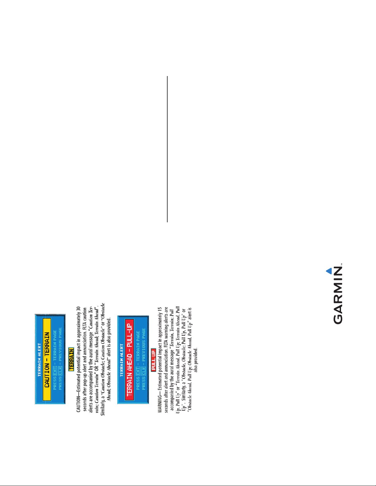
TAWS - units equipped with TAWS have been enhanced with software v3.00.
These enhancements reduce the amount of TAWS nuisance alerts but do not
change the operating characteristics to the pilot in any signifi cant manner. The
following Forward Looking Terrain Alerting Caution and Warnings should be
adhered to when displayed:
Annunciation Description
Approach Annunciation Table –The annunciation description for LOW ALT
has changed.
For LNAV+V, LNAV/VNAV, or LPV approaches,
the LOW ALT annunciation indicates the aircraft’s
estimated height is lower than the Final Approach
Waypoint height by more than the current VPL plus
50 meters. This annunciation will not be active when
TAWS is operating on units equipped with TAWS.
LOW ALT
(lower window)
400W/500W Series Optional Displays Pilot’s Guide Addendum
XM Weather
The XM Weather Function is capable of displaying graphical weather information
through the XM Satellite Radio Service when activated in the optional installation
of the GDL69/69A. Software Upgrade v3.00 adds capability to display three
new weather products: Lightning (LTNG), Cell Movement (CELL MOVE) and
Winds Aloft, all of which are displayed on the NAV pages of the 400W/500W
Series Units.
Lightning (LTNG)
When enabled, lightning strikes and cells are shown. Lightning information
indicates the location of cloud-to-ground lightning strikes noted by yellow plus
(+) signs.
To view XM Weather Lightning Strikes: while viewing the XM Weather page,
verify “LTNG” is displayed in the upper left corner. If “LTNG” is not displayed,
press the small right knob to highlight the displayed fi eld and then turn the
small right knob to change the fi eld to “LTNG”. Press the small right knob
again to stop highlighting the fi eld.
Cell Movement (CELL MOVE) shows the storm cells identifi ed by the ground-
based system. The movement is depicted by an arrow. The tip of the arrow
represents where the cell is expected to be in 10 minutes from the time the cell
location was determined.
To view XM Weather Cell Movement: while viewing the XM Weather page,
verify “CELL MOVE” is displayed in the upper left corner. If “CELL MOVE” is
small right knob again to stop highlighting the fi eld.
not displayed, press the small right knob to highlight the displayed fi eld and
then turn the small right knob to change the fi eld to “CELL MOVE”. Press the
2