

Garmin Appliance Data Pilot's Guide Addendum
400W / 500W Series
Garmin Optional Displays
Pilot’s Guide Addendum For:
• GDL 69/69A XM Satellite Datalink
• GDL 88 ADS-B Transceiver
• GTX 330/330D TIS
• Garmin TAWS (GPS 500W & GNS 530W)
• Garmin HTAWS (Helicopter Installations)
• Terrain Proximity (Helicopter Installations)
• Garmin GTS 8XX Series TAS
• Connext

Foreward
This Pilot’s Guide Addendum is written for:
• Garmin GPS 400W, GNC 420W/420AW, and GNS 430W/430AW Main System Software Version 2.00, 3.00, 3.30, 4.00, 5.00,
5.10, 5.20, or later
• Garmin GPS 500W & GNS 530W/530AW Main System Software Version 2.00, 3.00, 3.30, 4.00, 5.00, 5.10, or later
• GTX 330/330D Main Software Version 4.05
• GDL 69/69A Main Software Version 3.02 or later
Some differences in operation may be observed when comparing the information in this manual to earlier or later software versions.
© 2014 Garmin Ltd. or its subsidiaries. All Rights Reserved.
Garmin International, Inc., 1200 East 151st Street, Olathe, KS 66062, U.S.A.
Tel. 913/397.8200 or 800/800.1020 Fax 913/397.8282
Garmin AT, Inc., 2345 Turner Rd., S.E., Salem, Oregon 97302, U.S.A.
Tel: 503/581.8101 Fax: 503/364.2138
Garmin (Europe) Ltd., Liberty House, Bulls Copse Road, Hounsdown Business Park, Southampton, SO40 9RB, U.K.
Tel. +44 (0) 870 850 1243 Fax +44 (0) 238 052 4004
Garmin Singapore Pte. Ltd., 46 East Coast Road, #05-06 Eastgate, Singapore 428766
Tel : (65) 63480378 Fax : ( 65 ) 63480278
Except as expressly provided herein, no part of this addendum may be reproduced, copied, transmitted, disseminated, downloaded,
or stored in any storage medium, for any purpose without the express prior written consent of Garmin. Garmin hereby grants permission to download a single copy of this manual and of any revision to this manual onto a hard drive or other electronic storage medium
to be viewed and to print one copy of this manual or of any revision hereto, provided that such electronic or printed copy of this manual
or revision must contain the complete text of this copyright notice and provided further that any unauthorized commercial distribution
of this manual or any revision hereto is strictly prohibited. Information in this document is subject to change without notice. Garmin
reserves the right to change or improve its products and to make changes in the content without obligation to notify any person or organization of such changes or improvements.
Garmin® is a registered trademark, and GTX™ and GDL™ are trademarks of Garmin Ltd. or its subsidiaries and may not be used without
the express permission of Garmin Ltd. or its subsidiaries. Sirius and XM are trademarks of SiriusXM Radio Inc.
The screen display examples shown in this addendum are taken from the GNS 430W and GNS 530W. TIS and Weather Data Link
Display Interface functionality is the same for the 400W and 500W Series Units. TIS Traffic Display and Weather Data Link are available only
when the 400W/500W units are configured with the GTX 330 Mode S Transponder and GDL 69/69A Data Link Transceiver, respectively.
November 2014 190-00356-30 Revision L
190-00356-30 Rev L
Introduction
Warnings and Cautions
WARNING: Terrain data are obtained from third party sources. Garmin is not able to independently verify the accuracy of this
data which should be used only as an aid for situational awareness. Terrain data must not be used as the sole basis for decisions or maneuvers to avoid terrain or obstacles. Terrain data must not be used for navigation.
WARNING: Do not use data link weather information for maneuvering in, near, or around areas of hazardous weather. Information contained within data link weather products may not accurately depict current weather conditions.
WARNING: Do not use the indicated data link weather product age to determine the age of the weather information
shown by the data link weather product. Due to time delays inherent in gathering and processing weather data for data link
transmission, the weather information shown by the data link weather product may be significantly older than the indicated
weather product age.
CAUTION: Use the 400W/500W Series Units at your own risk. To reduce the risk of unsafe operation, carefully review and
understand all aspects of the Owner’s Manual and the Flight Manual Supplement, and thoroughly practice basic operation
prior to actual use.
CAUTION: The Global Positioning System is operated by the United States government, which is solely responsible for its
accuracy and maintenance. The system is subject to changes which could affect the accuracy and performance of all GPS
equipment. Although Garmin 400W/500W Series Units are precision electronic NAVigation AIDS (NAVAID), any NAVAID can be
misused or misinterpreted and therefore become unsafe.
CAUTION: The Jeppesen database incorporated in the Garmin 400W/500W Series Units must be updated regularly in order to
ensure that its information is current. Updates are released every 28 days. A database information packet is included in your
Garmin 400W/500W Series Unit package. Pilots using an out-of-date database do so entirely at their own risk.
CAUTION: The Weather Data Link, TIS, TAWS, HTAWS, and TERRAIN information contained in this Pilot’s Guide Addendum is
not intended to replace the documentation that is supplied with the applicable Garmin 400W/500W Series Unit and the GTX
330 Transponder. The user must know how to operate the 400W/500W Series Unit and be knowledgeable of the information in
the 400W/500W Pilot’s Guide.
TIS CAUTION: TIS is NOT intended to be used as a collision avoidance system and does not relieve pilot responsibility to “see
and avoid” other aircraft. TIS should not be used for avoidance maneuvers during IMC or other times when there is no visual
contact with the intruder aircraft. TIS is intended only to assist in visual acquisition of other aircraft in VMC. Avoidance maneuvers are not recommended, nor authorized, as a direct result of a TIS intruder display or TIS alert.
While TIS is a useful aid to visual traffic avoidance, it has some system limitations that must be fully understood to ensure
proper use. Many of these limitations are inherent in secondary radar surveillance. In other words, the information provided by
TIS will be no better than that provided to ATC.
NOTE: Do not rely solely upon data link services to provide Temporary Flight Restriction (TFR) information. Always confirm
TFR information through official sources such as Flight Service Stations or Air Traffic Control.
NOTE: For software version 4.00 and later: when configured for helicopters (the helicopter icon will be displayed), black, circular or oblong “cutouts” will be displayed on the Terrain Page around airports and heliports, to enhance viewing of the information displayed for those locations. The Terrain legend (shown in the lower right of the display on the Terrain Page) defines the
color black as -500 ft. However, this does not apply to the black cutouts surrounding the airports and heliports. The cutouts are
for display purposes only and do not affect the performance of HTAWS.
190-00356-30 Rev L
i

Introduction
Table of Contents
Table of Contents
Part One:
Traffic Information Service (TIS) Interface ................... 1
Section 1: TIS Operation and Symbology ....................1
TIS Operation ............................................................................1
How TIS differs from TCAS .........................................................2
TIS Limitations ..........................................................................2
Improving TIS ............................................................................3
TIS Symbology ..........................................................................3
Section 2: Control and Display .....................................5
TIS Traffic Display Status and Pilot Response ..............................5
Traffic Ground Track .................................................................6
Traffic Warning Window ............................................................6
Traffic Page ...............................................................................6
Traffic Page Display Range ........................................................6
Map Page .................................................................................7
Configuring TIS Traffic Data on the Map Page .......................7
Highlighting TIS Traffic Using Map Page Panning ........................8
Section 3: TIS Operational Procedures ........................ 9
Introduction ..............................................................................9
Power-Up Test ...........................................................................9
Manual Override .....................................................................10
Flight Procedures ....................................................................10
After Landing ..........................................................................10
Part Two: XM Radio Interface ....................................11
Section 1: Introduction ...............................................11
Overview ................................................................................11
SiriusXM Satellite Radio Pages ................................................11
XM NAV Pages ..................................................................11
XM WPT Pages ..................................................................12
XM AUX Pages ..................................................................12
Section 2: SiriusXM Weather ....................................... 12
Weather Product Age ..............................................................13
SiriusXM Weather ...................................................................14
NEXRAD U.S. and Canadian Coverage ...............................15
NEXRAD Intensity ..............................................................15
NEXRAD Abnormalities ......................................................15
NEXRAD Limitations ..........................................................16
SiriusXM Weather METARs ......................................................17
Textual METAR Page ..........................................................18
Textual METAR/TAF Code ..................................................19
TAF Page ...........................................................................19
TFR Information ......................................................................19
Lightning (LTNG) .....................................................................21
Cell Movement (CELL MOVE) ..................................................21
Winds Aloft .............................................................................22
Winds Aloft Altitude ..........................................................23
Section 3: XM AUX Pages ............................................ 23
XM Information Page .............................................................23
XM WX Timestamps ................................................................24
Section 4: SiriusXM Satellite Radio Audio ................. 25
Selecting categories ...........................................................26
Selecting channels .............................................................26
XM Audio Menu .....................................................................27
Add to Presets List ..................................................................27
Enter Channel Number ............................................................28
Display Channel In List ............................................................28
Display Artist In List ................................................................29
Display Title In List ..................................................................29
Enable/Mute Audio Output ......................................................30
Change Volume ......................................................................30
Part Three: TAWS Interface ......................................... 31
Section 1: Introduction ...............................................31
Overview ................................................................................31
Operating Criteria ...................................................................31
Limitations ..............................................................................31
Section 2: TAWS Operation .........................................32
TAWS Alerting.........................................................................32
Baro-Corrected Altitude ..........................................................32
Power Up ...............................................................................32
TAWS Page .............................................................................32
Inhibit Mode ...........................................................................33
External TAWS Inhibit Control ............................................34
TAWS Manual Test ..................................................................34
TAWS Symbols ........................................................................34
General Database Information .................................................36
Database Versions ...................................................................36
Database Updates ..................................................................37
Terrain/Obstacle Database Areas of Coverage ..........................37
Section 3: TAWS Alerts ................................................38
Forward Looking Terrain Avoidance .........................................38
Premature Descent Alerting (PDA) ...........................................39
Excessive Descent Rate Alert (EDR) ..........................................40
Negative Climb Rate After Takeoff Alert (NCR) .........................40
“Five-Hundred” Aural Alert .....................................................42
TAWS Not Available Alert ........................................................42
TAWS Failure Alert ..................................................................42
TAWS Alert Summary ..............................................................42
Pilot Actions ...........................................................................44
ii
190-00356-30 Rev L

Introduction
Table of Contents
Part Four: HTAWS Interface ........................................45
Section 1: Introduction ...............................................45
Overview ................................................................................45
Limitations ..............................................................................45
Section 2: HTAWS Operation ......................................46
HTAWS Alerting ......................................................................46
Baro-Corrected Altitude ..........................................................46
Power Up ...............................................................................46
HTAWS Page ...........................................................................46
Page Menu ........................................................................47
Inhibit Mode ...........................................................................48
External HTAWS Inhibit Control ..........................................48
Reduced Protection Mode .......................................................48
Mute Active Caution ...............................................................49
HTAWS Manual Test ................................................................50
HTAWS Legend .......................................................................50
HTAWS Symbols ......................................................................51
Airport/Heliport Terrain “Cutouts” ...........................................52
General Database Information .................................................52
Database Versions ...................................................................52
Database Updates ..................................................................53
Terrain Database Areas of Coverage ........................................54
Obstacle Database Areas of Coverage .....................................54
Section 3: HTAWS Alerts .............................................54
Forward Looking Terrain Avoidance .........................................55
Voice Call Out Aural Alert ........................................................55
HTAWS Not Available Alert ......................................................56
HTAWS Failure Alert ................................................................56
HTAWS Alert Summary ............................................................56
Pilot Actions ...........................................................................57
Voice Call Out Selection .....................................................58
Part Five: Terrain Proximity Interface .......................59
Introduction ............................................................................59
Displaying Terrain Proximity .....................................................59
Terrain Proximity 120° Arc or 360° Rings .................................60
Terrain Proximity Aviation Data ................................................60
Terrain Proximity Legend .........................................................61
Terrain Proximity Limitations....................................................62
System Status .........................................................................62
Part Six: Garmin GTS 8XX Series Interface ...............63
Introduction ............................................................................63
GTS 8XX Series Description .....................................................63
Power-up Self-Test ..................................................................63
User-initiated Test ...................................................................64
Voice Announcements .............................................................64
Switching Between Standby and Operating Modes ..................64
190-00356-30 Rev L
Altitude Display Mode .............................................................65
Traffic Page .............................................................................65
Traffic Warning Window ..........................................................66
Traffic Page Display Range ......................................................66
Configuring Traffic Data on the Map Page ................................67
Highlighting Traffic Data Using Map Panning ...........................68
Monitoring Traffic ....................................................................68
Failure Response .....................................................................68
Description of Traffic Advisory Criteria ......................................68
Part Seven: Garmin GDL 88/88D Interface ................69
Section 1: Introduction ...............................................69
Section 2: FIS-B Weather .............................................70
Flight Information Services (FIS) Description .............................70
Graphical Weather Display ......................................................70
NEXRAD ...........................................................................70
NEXRAD Description ...............................................................71
NEXRAD Abnormalities ......................................................71
NEXRAD Limitations ..........................................................71
NEXRAD Intensity ..............................................................72
NEXRAD Options ...............................................................72
Continental US NEXRAD (CONUS) .....................................72
Regional NEXRAD .............................................................73
Graphical METARs .............................................................73
Section 3: Traffic ..........................................................75
Introduction ............................................................................75
Power-Up Self-Test ..................................................................75
User-initiated Test ...................................................................76
Altitude Display Mode .............................................................76
Switching Between Standby and Operating Modes ..................77
Traffic Page .............................................................................78
Traffic Alert Pop-Up .................................................................79
Traffic Page Display Range ......................................................80
Configuring Traffic Data on the Map Page ................................80
Highlighting Traffic Data Using Map Panning ...........................81
GDL 88/88D Status .................................................................81
Pressure Altitude Report (PALT RPT) ...................................82
Anonymous (ANON) Mode ................................................82
Failure Response .....................................................................82
RYAN TCAD ............................................................................83
Setting Altitude Display Mode ............................................83
TCAD Traffic Page Menu ....................................................83
Ryan TCAD Setup ..............................................................84
Traffic Watch .....................................................................84
iii

Introduction
Table of Contents
Part Eight: Garmin Connext Interface ....................... 85
Section 1: Introduction ...............................................85
Starting with Connext .............................................................85
Section 2: Bluetooth Status ........................................86
Pairing Your Devices ................................................................86
Editing the Bluetooth Name ....................................................86
View Device Details .................................................................87
Auto-Reconnect ......................................................................87
To toggle the auto-reconnect status: .................................87
Unpair Device .........................................................................88
Method 1 ..........................................................................88
Method 2 ..........................................................................88
Section 3: Device Configuration ................................88
Section 4: Flight Plan Import .....................................89
Importing a Flight Plan with Connext ......................................89
Viewing the Connext Flight Plan Import Page ..........................90
Deleting a Pending Flight Plan .................................................90
Delete All Pending Flight Plans ................................................90
View User Waypoint List ..........................................................91
iv
190-00356-30 Rev L
Part One: Section 1
TIS Operation and Symbology
Part One:
• Your aircraft must be equipped with a Mode S
Traffic Information Service
(TIS) Interface
Section 1: TIS Operation and
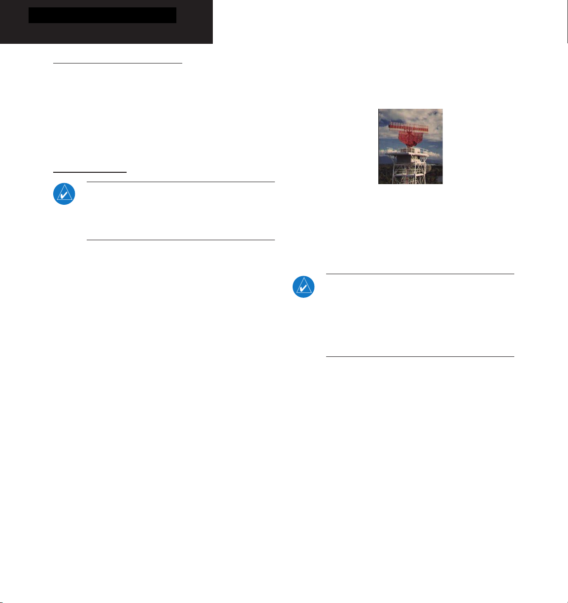
• You must be within range of a Mode S radar that
• The “intruder” aircraft must be equipped with a
Symbology
TIS Operation
NOTE: Part One of this Addendum assumes the
user has experience operating the 400W/500W
Series units and the Garmin GTX 330 Transponder.
The Traffic Information Service (TIS) provides a graphic
display of traffic advisory information in the cockpit for
non-TCAS (Traffic alert and Collision Avoidance System)
equipped aircraft. TIS is a ground-based service providing
relative location of all ATCRBS (Air Traffic Control Radar
Beacon System) Mode A and Mode C transponderequipped aircraft within a specified service volume. The
TIS ground sensor uses real-time track reports to generate
traffic notification. TIS Traffic display is available to
aircraft equipped with a Mode S Data Link such as the
Garmin GTX 330 Transponder. TIS Traffic from a GTX
330 Transponder can then be displayed on a Garmin
400W/500W Series unit. Surveillance data includes
all transponder-equipped aircraft within the coverage
volume. Aircraft without an operating transponder are
invisible to TIS. TIS displays up to eight traffic targets
within seven nautical miles horizontally from 3000 feet
below to 3500 feet above the requesting aircraft.
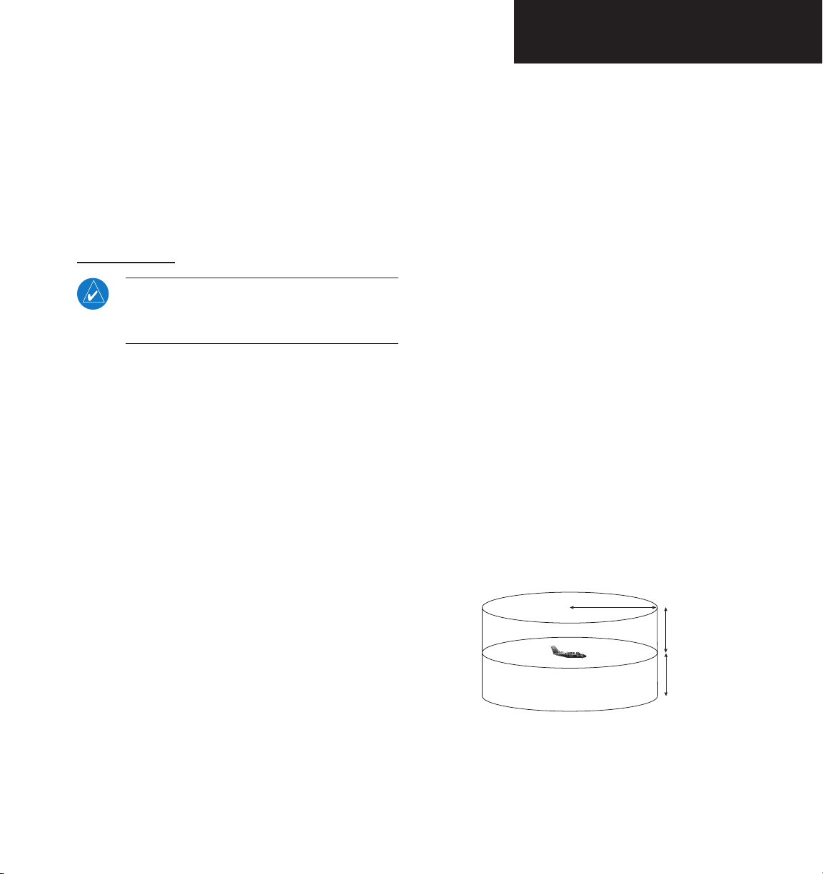
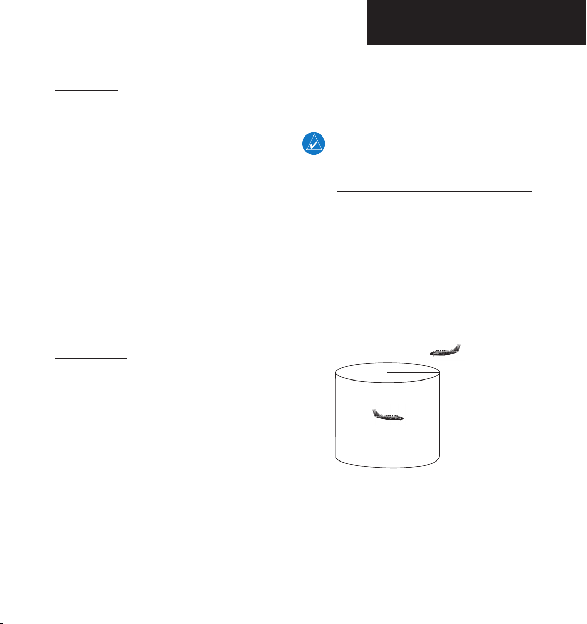
• The “intruder” aircraft must be within the TIS
• Both your aircraft and the intruder aircraft must
Always remember that TIS cannot alert you to
the presence of aircraft that are not equipped with
transponders, nor can it alert you to aircraft that may be
nearby, but obscured from the ground surveillance radar
by intervening terrain.
data link transponder, such as the GTX 330.
provides the TIS service. Not all Mode S ground
radars provide TIS service.
transponder, and that transponder must be turned
on. Aircraft that are not equipped with operating
transponders will not be visible to the Mode S
surveillance radar.
coverage volume for your aircraft. TIS displays
up to eight traffic targets within seven nautical
miles horizontally from the requesting aircraft,
and from 3,000 feet below to 3,500 feet above
the requesting aircraft.
be visible to the Mode S surveillance radar on the
ground.
7.0 NM
3,500 ft
3,000 ft
The TIS is a ground-based service that displays nearby
aircraft on your 400W/500W-series display. For the TIS
feature to inform you of a nearby aircraft’s presence,
several conditions must be met:
190-00356-30 Rev L
TIS Coverage Volume (not to scale)
1
Part One: Section 1
TIS Operation and Symbology
How TIS differs from TCAS
The main difference between TIS and TCAS is the
source of surveillance data. TCAS uses an airborne
interrogator with a one-second update rate, while TIS uses
on the underside of the aircraft) and the ground-based
radar antenna, the signal may be temporarily interrupted.
Other limitations and anomalies associated with TIS are
described in the AIM, Sections 4-5-6 and 4-5-8.
the terminal Mode S ground interrogator and its Data Link
to provide about a five-second update rate. The range
accuracy of TIS and TCAS is similar.
TIS Limitations
NOTE: This section on TIS Limitations is not com-
prehensive. Garmin recommends the user review
the TIS Limitations section of the Aeronautical
Information Manual, Sections 4-5-6 and 4-5-8.
TIS is NOT intended to be used as a collision avoidance
system and does not relieve the pilot of responsibility to
“see and avoid” other aircraft. TIS should not be used for
avoidance maneuvers during IMC or other times when
there is no visual contact with the intruder aircraft. TIS
is intended only to assist in visual acquisition of other
aircraft in VMC. No recommended avoidance maneuvers
are provided for, nor authorized, as a direct result of a TIS
intruder display or TIS advisory.
TIS information is collected one radar scan prior to
While TIS is a useful aid to visual traffic avoidance, it
has some system limitations that must be fully understood
to ensure proper use. Many of these limitations are
inherent in secondary radar surveillance. In other words,
the information provided by TIS will be no better than
that provided to ATC. TIS will only display aircraft with
operating transponders installed.
TIS relies on surveillance of the Mode S radar, which
is a “secondary surveillance” radar similar to the ATCRBS.
TIS operation may be intermittent during turns or other
maneuvering. TIS is dependent on two-way, “line-ofsight” communication between the aircraft and the Mode
S radar. Whenever the structure of the client aircraft
comes between the transponder antenna (usually located
2
190-00356-30 Rev L
the scan during which the uplink occurs. Therefore, the
surveillance information is approximately five seconds old.
In order to present the intruders in a “real time” position,
the TIS ground station uses a “predictive algorithm” in its
tracking software. This algorithm uses track history data to
extrapolate intruders to their expected positions consistent
with the time of display in the cockpit. Occasionally,
aircraft maneuvering will cause this algorithm to induce
errors in the 400W/500W display. These errors primarily
affect relative bearing information and traffic target track
vector (it will lag); intruder distance and altitude will
remain relatively accurate and may be used to assist in
“see and avoid.” Some of the more common examples of
these errors follow:
Garmin is not responsible for Mode S geo-
graphical coverage. Operation of the ground
stations is the responsibility of the FAA. Refer
to the Aeronautical Information Manual for a
Terminal Mode S Radar Site Map covering the
U.S.
NOTE: TIS will be unavailable at low altitudes in
many areas of the U.S., particularly in mountainous regions. Also, when flying near the “floor”
of radar coverage in a particular area, intruders
below the client aircraft may not be detected by
TIS.

Part One: Section 1
TIS Operation and Symbology
• When client or intruder aircraft maneuvers exces-
sively or abruptly, the tracking algorithm may
report incorrect horizontal position until the
maneuvering aircraft stabilizes.
• When a rapidly closing intruder is on a course that
crosses the client aircraft course at a shallow angle
(either overtaking or head on) and either aircraft
abruptly changes course within ¼ NM, TIS may
display the intruder on the opposite side of the
client than it actually is.
These are relatively rare occurrences and will be
corrected in a few radar scans once the course has
stabilized.
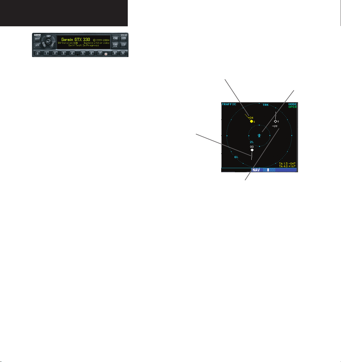
TIS Symbology
TIS traffic is displayed on the 400W/500W Series unit
according to TCAS symbology, graphically displayed on
a dedicated graphical page (Traffic Page; see below), and
on the moving Map Page. A Traffic Advisory (TA) symbol
appears as a solid yellow circle (or half circle on the outer
range ring if the traffic is outside the range of the dedicated
Traffic Page). Proximity Advisories (PA) are displayed as a
solid diamond, and other traffic is displayed as an open
diamond. PA and other traffic is normally displayed in
white, or it may be alternatively configured for display
in cyan. When configured for cyan, the traffic page range
rings and markings are displayed in white. Altitude
deviation from own aircraft altitude is displayed above the
Improving TIS
Users of TIS can render valuable assistance in the
correction of malfunctions by reporting their observations
of undesirable performance. Reporters should identify
the time of observation, location, type and identity of
aircraft, and describe the condition observed; the type
of transponder processor and software in use can also be
useful information. Since TIS performance is monitored
target symbol if traffic is above own aircraft altitude, and
below the symbol if they are below own aircraft altitude.
Altitude trend is displayed as an up arrow (> +500 ft/min),
down arrow (< -500 ft/min), or no symbol if less than 500
ft/min rate in either direction.
• Traffic Advisories (TA)—Yellow
• Proximity Advisories (PA)—White
by maintenance personnel other than ATC, it is suggested
that malfunctions be reported in the following ways:
• By telephone to the nearest Flight Service Station
• Other—White (may be configured as Cyan)
(FSS) facility.
(may be configured as Cyan)
• By FAA Form 8000-7, Safety Improvement Report,
a postage-paid card designed for this purpose.
These cards may be obtained at FAA FSSs, General
Aviation District Offices, Flight Standards District
Offices, and General Aviation Fixed Based Operations.
190-00356-30 Rev L
3
Part One: Section 1
TIS Operation and Symbology
The TIS audio alert is generated from the
GTX 330 whenever the number of Traffic Advisories on the 400W/500W display increases
from one scan to the next. Limiting Traffic
Advisories only reduces the “nuisance” alerting
due to proximate aircraft. For example, when
the first Traffic Advisories appears on the TIS
display, the user is alerted audibly. So long as
a single aircraft remains on the TIS display, no
further audio alert is generated. If a second (or
more) aircraft appears on the display, a new
audio alert is sounded.
If the number of Traffic Advisories on the TIS
display decreases and then increases, a new
audio alert is sounded. The TIS audio alert is
also generated whenever TIS service becomes
unavailable. The volume, pitch, and duration
of the audio alert (including the choice between
a male or female voice) is configured during
installation.
The following TIS audio alerts are available:
• “Traffic” —TIS traffic alert is received.
• “Traffic Not Available” — TIS service is not
available or out of range.
Traffic Advisory (TA)—This symbol is generated when traffic
meets the advisory criteria described in TIS Operational Proce
Traffic Ground Track is indicated
on the 400W/500W display by a
“target track vector”, a short line
displayed in 45-degree increments.
This vector shows the flight direc
tion of the traffic.
-
dures.
-
Own Aircraft
“Other” Traffic—This symbol represents
traffic detected within the selected display
range that does not generate a TA.
4
190-00356-30 Rev L

Part One: Section 2
TIS Controls and Display
Section 2: Control and Display
TIS Traffic Display Status and Pilot Response
• STBY — When the 400W/500W displays STBY
in the upper right hand corner of the display the
TIS system is in standby mode and cannot display
traffic data.
• OPER — When the 400W/500W displays OPER
in the upper right hand corner of the display the
TIS system is in operational mode and available
to display traffic on the Traffic or Map Page.
• AGE — If traffic data are not refreshed within
6 seconds, an age indicator (e.g., “AGE 00:06”)
is displayed in the lower right corner of the display (when displaying traffic). The pilot should
be aware that the quality of displayed traffic is
reduced in this condition.
• TRFC CST — If data are still not received between
six and twelve seconds, the “TRFC CST” (traffic
coasting) banner located above the AGE timer will
indicate that displayed traffic is held even though
the data are not current. The pilot should be aware
that the quality of displayed traffic is reduced in
this condition.
• UNAVAIL — After a 60 second period elapses with
• NO DATA — “NO DATA” is displayed when no
to “coast” (for the time period after 12 seconds
from the last receipt of a TIS message). The pilot
should be aware that traffic may be present but
not shown.
Traffic Page displaying “TRFC RMVD”
banner.
no data, TIS is considered to be unavailable. This
state is indicated by the text “UNAVAIL”. The pilot
should be aware that “UNAVAIL” could indicate
a TIS coverage limitation due to a line-of-sight
situation, a low altitude condition, no TIS service,
or a result of flying directly over the radar site
providing coverage (cone of silence).
data are being received from the GTX 330. The
pilot should be aware that this status may be a
normal mode of operation in a dual transponder
installation where the GTX 330 with TIS is not
the selected transponder. The GTX 330 may not
be powered on.
Traffic Age Indication showing “traffic coasting”.
• TRFC RMVD — If data are still not received after
twelve seconds, the “TRFC RMVD” banner will
indicate that traffic has been removed from the
display due to the age of the data being too old
190-00356-30 Rev L
• DATA FAIL — “DATA FAIL” is displayed when
data are being received from GTX 330, but there
was a failure detected in the data stream. The pilot
should see the dealer for corrective action.
• FAILED — “FAILED” is displayed when the GTX
330 has indicated it has failed. The pilot should
see the dealer for corrective action.
5
Part One: Section 2
TIS Controls and Display
Traffic Ground Track
Traffic ground track is indicated in the 400W/500W
display by a “target track vector”, a short line displayed
in 45° increments, extending in the direction of target
movement.
Traffic Page
TIS Traffic data are displayed on two 400W/500W
Series unit pages, the Traffic Page and the Map Page.
The 500W Series unit can also be configured to display
a traffic thumbnail window below the VLOC frequency
window. Unlike other forms of traffic, TIS traffic does
not require heading data to be valid on the map. The only
difference between TIS and other traffic data occurs on the
Traffic Page. If heading is available, then the traffic data
are compensated and displayed as heading-up. If it’s not
available, the Traffic Page is a track-up display. It is labeled
on the upper portion of the Traffic Page.
Traffic Page Display Range
Various display ranges can be selected for optimal
Traffic Target Track Vector.
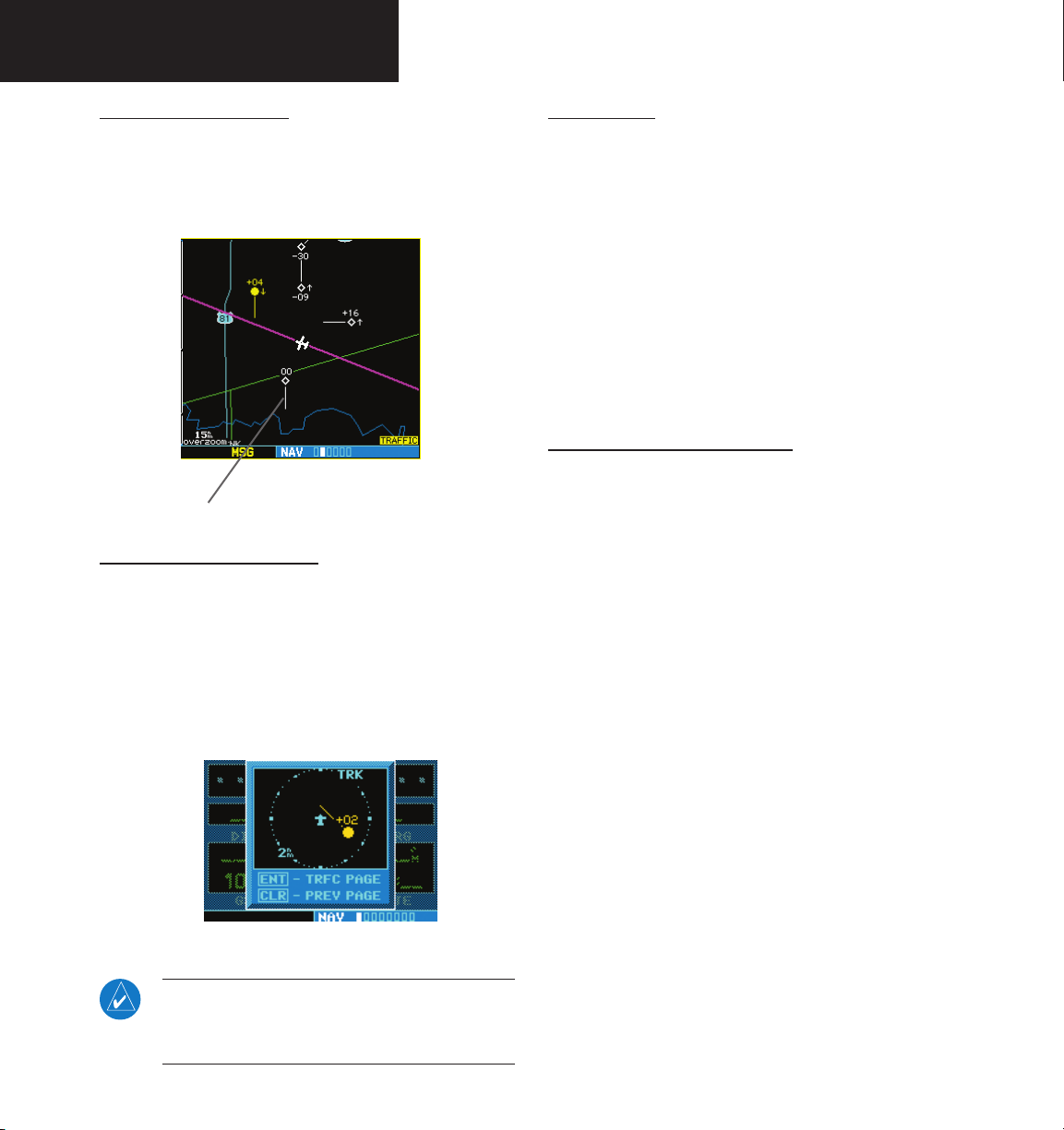
Traffic Warning Window
display of TIS traffic information.
To change the display range on the Traffic Page:
Press RNG to zoom through the range
When the unit is on any page (other than the NAV
Traffic Page or when a TAWS/Terrain, or Dead Reckoning
pop-up is displayed) and a traffic threat is imminent, the
Traffic Warning Window is displayed. The Traffic Warning
Window shows a small thumbnail map which can take
the user to the Traffic Page by pressing ENT, or go back to
the previous page by pressing CLR.
selections which are: 12/6 NM, 6/2 NM, and
2 NM.
Traffic Warning Window
NOTE: The Traffic Warning Window is disabled
when the aircraft ground speed is less than 30
knots or when an approach is active.
6
190-00356-30 Rev L
Part One: Section 2
TIS Controls and Display
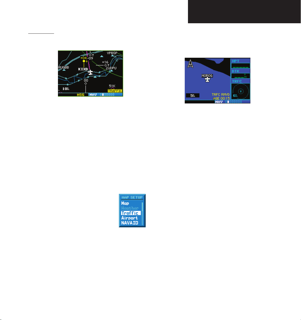
Map Page
TIS traffic is displayed on the Map Page in addition to
the Traffic Page.
The Map Page displaying traffic.
Configuring TIS Traffic Data on the Map Page
To configure TIS traffic on the Map Page:
1. Turn the small right knob to select the Map
Page.
2. Press the MENU key.
Turn the small right knob to select “Setup
Map?”
3. The flashing cursor highlights the GROUP field.
Turn the small right knob to select “Traffic” and
press ENT.
4. Turn the large right knob to select the desired
Traffic group option. Turn the
small right knob to select the
desired option and press ENT.
Repeat the step for Traffic Symbol
and Traffic Label.
5. Press CLR to return the Map
Page.
From the Map Page you can display traffic in a
thumbnail format in any of the top three (400W Series)
or four (500W Series) data fields on the right side of the
Map Page.
Thumbnail Traffic displayed on the
GNS 430W.
NOTE: The thumbnail will display traffic
coasting “TRFC CST” or traffic removed
“TRFC RMVD” in the lower right when TIS
messages have been missed.
To display Thumbnail Traffic on the Map Page:
1. Turn the small right knob to select the Map
Page.
2. Press the MENU key and display the Page Menu.
3. Turn the small right knob to select “Change
Fields?” and press ENT.
4. Select one of the top three (400W Series) or four
(500W Series) configurable fields. Select “TRFC”
from the Select Field Type List and press ENT. Note
that the thumbnail range defaults to 6 NM and
cannot be changed.
The Traffic group selection menu allows the user to
choose from the following:
• All trfc - All traffic is displayed on the Map
Page.
• TA/PA - Only traffic advisories and proximity
advisories are displayed on the Map Page.
• TA only - Only traffic advisories are displayed on
the Map Page.
190-00356-30 Rev L
7
Part One: Section 2
TIS Controls and Display
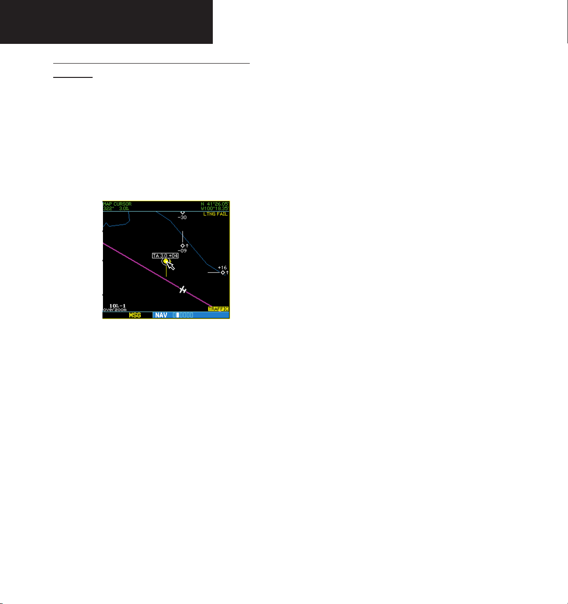
Highlighting TIS Traffic Using Map Page
Panning
Another Map Page feature is panning, which allows
you to move the map beyond its current limits without
adjusting the map scale. When you select the panning
function — by pressing the small right knob — a
target pointer will flash on the map display. A window
also appears at the top of the map display showing the
latitude/longitude position of the pointer, plus the bearing
and distance to the pointer from your present position.
Displaying traffic range and altitude separa-
tion using the Map Panning feature.
To activate the panning feature and pan the map
display:
1. Press the small right knob to activate the panning
target pointer.
2. Turn the small right knob to move up (turn
clockwise) or down (counterclockwise).
3. Turn the large right knob to move right (turn
clockwise) or left (counterclockwise).
4. To cancel the panning function and return to your
present position, press the small right knob.
When the target pointer is placed on traffic, the traffic
range and altitude separation are displayed.
8
190-00356-30 Rev L
Part One: Section 3
TIS Operational Procedures
Section 3: TIS Operational Procedures
Introduction
TIS warns the user with voice and visual traffic
advisories whenever it predicts an intruder to be a threat
(see illustration). Voice and visual data are sent from the
GTX 330. The user should not start evasive maneuvers
using information from the 400W/500W display or on
a traffic advisory only. The display and advisories are
intended only for assistance in visually locating the traffic,
due to the lack in resolution and coordination ability. The
flight crew should attempt to visually acquire the intruder
aircraft and maintain a safe separation in accordance with
the regulatory requirements and good operating practice.
If the flight crew cannot visually acquire the aircraft, they
should contact ATC to obtain any information that may
assist concerning the intruder aircraft. Based on the above
procedures, minor adjustment to the vertical flight path
consistent with air traffic requirements are not considered
evasive maneuvers.
Power-Up Test
The TIS interface performs an automatic test during
power-up.
• UNAVAIL — When a 60 second period elapses
GTX 330 has failed. The “DATA FAIL” message
indicates data are being received from the GTX
330 but a failure was detected in the data stream.
The “NO DATA” message indicates that data are
not being received from the GTX 330.
NOTE: “NO DATA” may be a normal mode of
operation in a dual transponder installation
where the GTX 330 with TIS is not the selected
transponder.
with no data, TIS is considered to be unavailable.
This state is indicated by the text “UNAVAILABLE”
(500W Series) and “UNAVAIL” (400W Series).
The pilot should be aware that “UNAVAIL” could
indicate a TIS coverage limitation due to a line-ofsight situation, a low altitude condition, no TIS
service, or a result of flying directly over the radar
site providing coverage (cone of silence).
Intruder Aircraft
0.5 NM
+ 500 ft
• If the system passes the power-up test, the Standby
Screen appears on the Traffic Page.
• If the system passes the power-up test and the
aircraft is airborne (as determined by system
configuration at the time of installation, see your
installer for detailed criteria information), traffic
is displayable on the Traffic Page in operating
mode.
• If the system fails the power-up test, the “NO
DATA”, “DATA FAIL”, or “FAILED” message is
displayed. See your installer for corrective action
if the “DATA FAIL”, or “FAILED” message is
displayed. The “FAILED” message indicates the
190-00356-30 Rev L
This area within 34 seconds
Conditions for Traffic Advisories
The following condition causes TIS to display a Traffic
Advisory (TA) on the 400W/500W Series unit:
• The intruder aircraft approaches your aircraft on
a course that will intercept (defined by a 0.5 NM
horizontal radius and a relative altitude of ± 500
feet) your course within 34 seconds.
- 500 ft
9

Part One: Section 3
TIS Operational Procedures
Manual Override
The user can manually switch between standby (STBY)
and operating (OPER) mode of operation to manually
override automatic operation.
To place the display into operating mode from the
standby mode (to display TIS traffic):
1. Turn the cursor on and highlight “STBY”.
2. Turn the small right knob to select
“OPER?”.
3. Press ENT to confirm.
To place the display into standby mode from
operating mode (to stop displaying TIS traffic):
1. Turn the cursor on and highlight “OPER”.
2. Turn the small right knob to select “STBY?”
3. Press ENT to confirm.
“DATA FAIL” Message
The “NO DATA” message indicates that data
are not being received from the GTX 330.
NOTE: This may be a normal mode of opera-
tion in a dual transponder installation where
the GTX 330 with TIS is not the selected
transponder.
Flight Procedures
Once the aircraft is airborne (determined by system
configuration at the time of installation) the system
switches from standby mode to operating mode. The
400W/500W Series unit displays OPER in the upper right
hand corner of the display and begins to display traffic on
the Traffic or Map Page.
The TIS Traffic Advisory (TA) should alert the crew to
use additional vigilance to identify the intruding aircraft.
Any time the traffic symbol becomes a yellow circle or a
voice warning is announced, conduct a visual search for
the intruder. If successful, maintain visual contact to ensure
safe operation. See Section 2: Control and Display for a
description of pilot responses to TIS display messages.
After Landing
10
Once the aircraft is “ground-borne” (determined by
system configuration at the time of installation) the system
switches from operating mode to standby mode. The
400W/500W Series unit displays “STBY”. As described
previously, both the standby and operating modes can be
manually overridden by the display controls.
190-00356-30 Rev L

Part Two: Section 1
XM Radio Introduction
Part Two:
XM Radio Interface
Section 1: Introduction
Overview
The GDL 69 is a remote sensor that receives
broadcast weather data from a data service of SiriusXM
Satellite Radio Inc. The GDL 69A is similar to the GDL
69, but also receives audio entertainment broadcasts from
another service of SiriusXM Satellite Radio. The 400W
and 500W series units serve as the display and control
head for your remotely mounted GDL 69/69A radio.
Before the GDL 69/69A can be used, the unit must
be activated by SiriusXM Satellite Radio with a service
subscription through SiriusXM Satellite Radio. Please note
that the GDL 69 is a weather data link. The GDL 69A is a
weather data link and audio receiver. The data link service
and the audio entertainment services must be activated
separately.
Your GDL 69 or GDL 69A is shipped with one or two
radio hardware identifications, respectively. These IDs
serve as identification codes for your SiriusXM Satellite
Radio-equipped GDL 69/69A and are needed in the
activation process. The ID(s) is (are) attached to the
Activation Instructions and printed on a label on the back
of the unit. The IDs can also be retrieved through your
unit in the SiriusXM Satellite Radio Information page of
the Aux function. Contact your dealer or customer service
if you are unable to locate the radio hardware IDs.
Weather and/or audio data from your GDL 69/69A are
provided by SiriusXM Satellite Radio, a company separate
and independent from Garmin Corporation. Have your
radio hardware IDs ready before contacting SiriusXM
Satellite Radio. During the process, you can select services
for subscription. Keep in mind that the GDL 69 has no audio
capability, audio services will not be available with the unit.
190-00356-30 Rev L
Follow the GDL 69/69A XM Satellite Radio Activation
Instructions (190-00355-04) enclosed with your GDL
69/69A unit to activate the XM products.
The latest subscription information is available at:
http://www.garmin.com/xm/
SiriusXM Satellite Radio Pages
To reach the SiriusXM Satellite Radio pages:
1. From any page, press and hold CLR to select
2. Turn the large right knob to select the AUX
3. Turn the small right knob to select the
XM Weather page is displayed in the NAV page group.
The XM Audio function pages are displayed in the AUX
page group.
XM NAV Pages
When a GDL 69 or GDL 69A is installed, the following
XM-related pages appear in the NAV group of pages:
• Map Page. The Map page (the second page in the
• XM Weather Page. The XM Weather page is inserted
the Default NAV Page. (You may skip this step
if you are already viewing any of the main
pages.)
page group. “AUX” appears in the lower right
corner of the screen.
SiriusXM Audio, SiriusXM Satellite Radio
Information, or XM WX Timestamps pages.
NAV page group) becomes capable of displaying
weather data and the boundaries of areas with
Temporary Flight Restrictions (TFRs).
in the NAV page group, immediately before the
Terrain page. This page is like the map page, but
can show NEXRAD weather data, colored flags
showing which airports have METARs (current
weather observations—Meteorological Aerodrome
Reports), Lightning (LTNG) reports, Cell Movement, or Winds Aloft.
11

Part Two: Section 2
XM Weather
XM WPT Pages
When a GDL 69 or GDL 69A is installed, two SiriusXM
Weather-related pages are added to “airport” pages in the
WPT page group:
• Textual METAR Page. The Textual METAR
page shows the text of the most recent METAR
(Meteorological Aerodrome Report) that has been
received for an airport.
• TAF Page. The TAF page shows the text of the
most recent TAF (Terminal Aerodrome Forecast)
that has been received for an airport.
XM AUX Pages
When a GDL 69 or GDL 69A is installed, the following
XM pages appear in the AUX group of pages:
• XM Audio Page (GDL 69A only). See Section 4
below for a description of this page.
• XM Information Page. This page contains infor-
mation that you will use when activating your XM
satellite radio subscription. It also reports the GDL
69/69A’s software version number. SiriusXM Satellite Radio and SiriusXM Weather subscriptions are
sold separately.
• XM Weather Timestamp Pages. This page show
timestamp data for the most recently received XM
weather data.
Section 2: SiriusXM Weather
The SiriusXM Weather Function is capable of displaying
graphical weather information through the SiriusXM
Satellite Radio Service when activated in the optional
installation of the GDL 69/69A. Next Generation Weather
Radar (NEXRAD), METARs symbols (METAR), Lightning
(LTNG), Cell Movement (CELL MOVE), and Winds Aloft
(WINDS) are displayed on the NAV pages. The types of
products available depend on the subscription service
with XM Satellite Radio.
Once you have activated an aviation weather service
from SiriusXM Weather, the 400W/500W series unit can
display the following aviation-related data:
• NEXRAD. An indication of the intensity of
weather radar echoes from the National Weather
Service’s network of NEXRAD (NEXt generation
RADar) sites can be shown on the SiriusXM
Weather Page and can optionally be overlaid on
the Map page. (Both these pages are in the NAV
page group.) Canadian Radar may also be available.
• Radar Coverage. Whenever NEXRAD is shown, a
cross-hatch pattern indicates the limits of NEXRAD
radar coverage. The cross-hatched area shows
where NEXRAD information is unavailable.
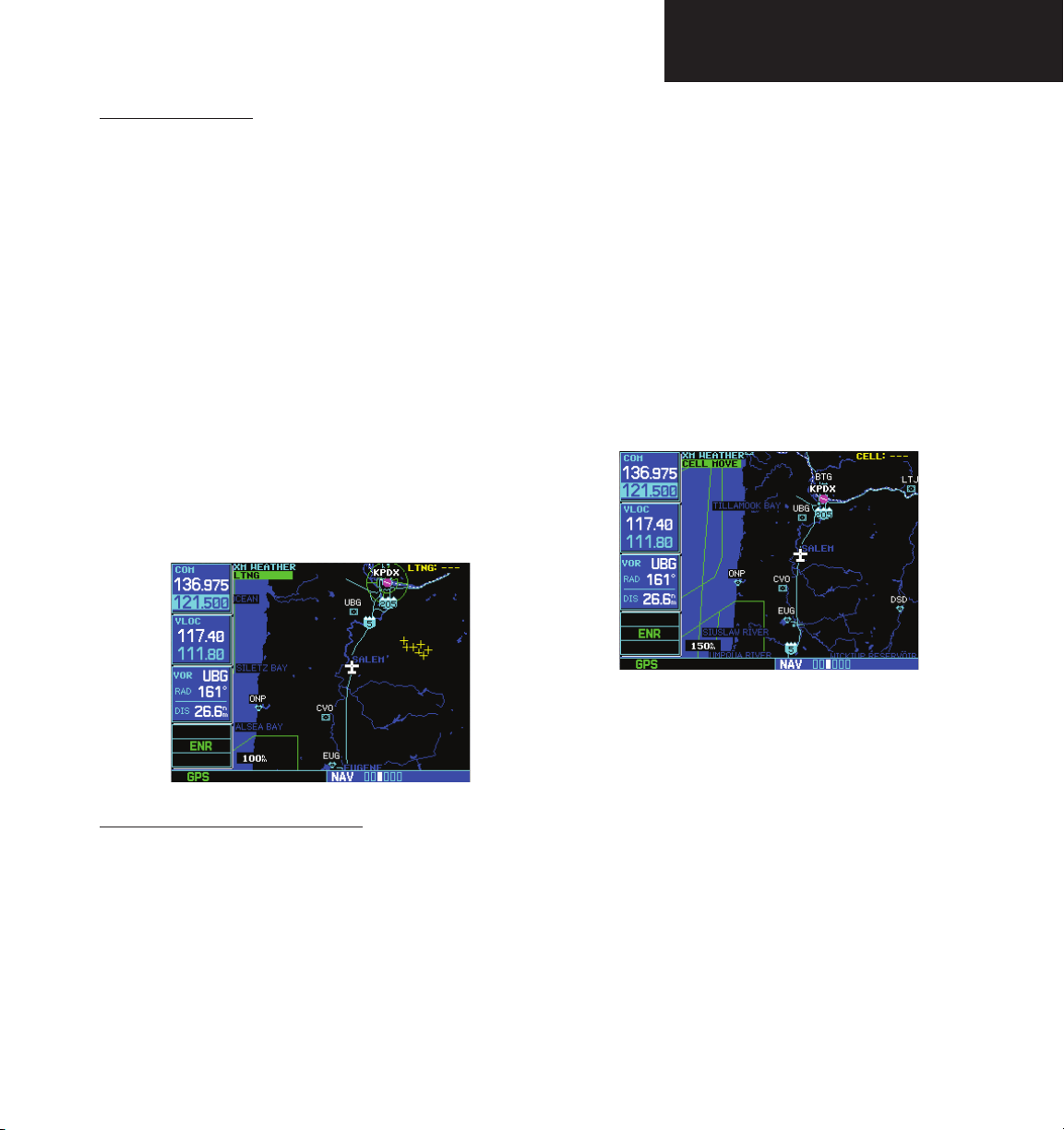
• Lightning (LTNG). When enabled, lightning
strikes and cells are shown as yellow “+” signs.
Lightning information indicates the location of
cloud-to-ground lightning strikes.
12
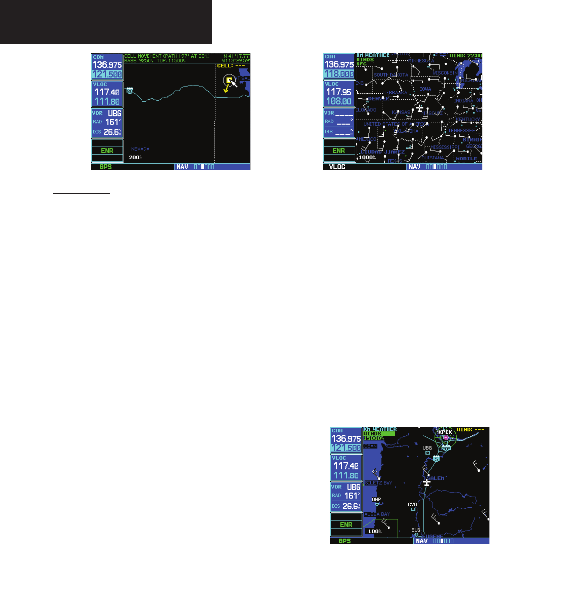
• Cell Movement (CELL MOVE). When enabled,
Cell Movement shows the storm cells identified
by the ground-based system. The movement
is depicted by an arrow. The tip of the arrow
represents where the cell is expected to be in
10 minutes from the time the cell location was
determined.
190-00356-30 Rev L
Part Two: Section 2
XM Weather
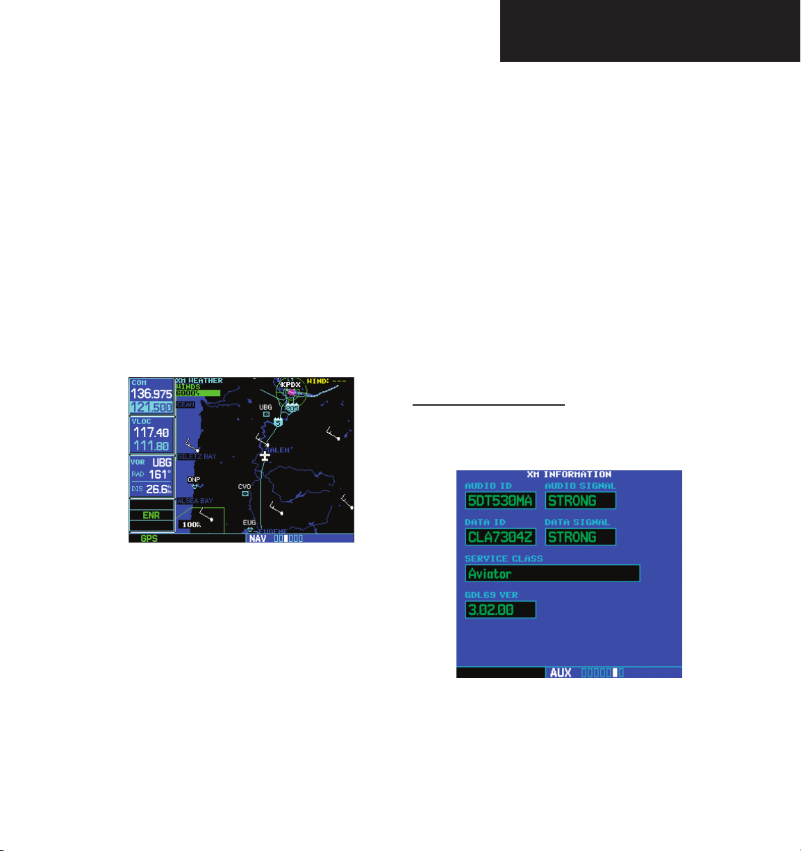
• Winds Aloft (WINDS). The Winds Aloft
selection provides the pilot with wind speed
and direction. The winds at a given altitude
are selected in the Winds Aloft Alt below the
WINDS selection. The selected altitude is shown
along with the product time.
• Textual Meteorological Aerodrome Reports
(METARs). When you zoom in to show the airport symbol associated with the colored flag for a
graphical METAR, and move the Map Pointer to
highlight that airport, you can then press ENT to
see the Textual METAR page for that airport. The
Textual METAR page is one of the airport pages
of the WPT page group.
• Graphical Meteorological Aerodrome Reports
(METARs). The XM Weather page (in the NAV
page group) can show colored flags to indicate
the level of current weather conditions at those
airports for which textual METAR reports are
available. The flags are color-coded to indicate
the severity of the current weather at the airport:
cyan for VFR conditions, green for Marginal VFR
conditions, yellow for IFR conditions, or magenta
of Low IFR conditions.
• Terminal Aerodrome Forecast (TAFs). A TAF
page is added among the airport pages of the
WPT page group. The TAF page differs from the
Textual METAR page in that it describes forecast
future weather conditions rather than current
conditions.
• Temporary Flight Restrictions (TFRs). The
boundaries of areas with TFRs are outlined in
yellow on the Map and XM Weather pages of
the NAV page group. In the 500W-series, TFR
boundaries are also shown on the NAV main
page. You can obtain more information about a
190-00356-30 Rev L
TFR by bringing up the map cursor, moving the
map cursor to within the yellow outlined area,
and pressing the ENT key.
Weather Product Age
The age of the displayed weather product—or the
effective time of Winds Aloft predictions—is shown in the
upper right corner of the display. For example, if NEXRAD
is displayed, “0:05” indicates that the data are five minutes
old. If Winds Aloft predictions are being displayed, “10:00”
indicates the effective time for the displayed prediction is
10:00 AM.
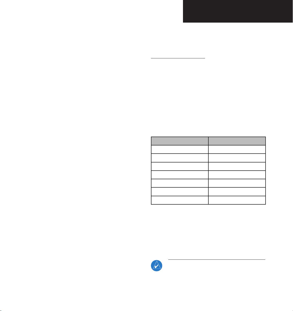
The data for each XM Weather product are updated
regularly from the GDL 69/69A. XM Weather products
expire after the following intervals:
Product Expiration Interval
METARs 90 minutes
NEXRAD/Radar Coverage 30 minutes
TFRs 60 minutes
TAFs 60 minutes
Lightning 30 minutes
SCITs 30 minutes
Winds Aloft Predictions 90 minutes
When the age of the displayed XM Weather product
reaches one half of its expiration time, the color of the
displayed time changes from green to amber. Expired XM
Weather products are never displayed. In the unlikely
event that the data should expire before a fresh update
is received, the time will be dashed out and the data
removed from the display.
NOTE: Product age for individual reports of
XM AIRMETs, SIGMETs, City Forecasts, County
Warnings, Cell Movement and TFRs are not
provided by XM Weather Service.
13
Part Two: Section 2
XM Weather
Product age indication for XM Icing Potential
and Turbulence is not included on the weather
map. The valid time for these products is
displayed on the weather map in place of the
generation time.
The valid time indication for XM Freezing Level,
Winds Aloft and Canada Winds Aloft is not displayed. Instead, the generation time for these
is displayed.
SiriusXM Weather
The National Weather Service’s network of WSR88D Doppler weather surveillance radars—also called
NEXRAD, for Next Generation Radar—has greatly
improved the detection of meteorological events such as
thunderstorms, tornados, and hurricanes. An extensive
network of NEXRAD weather radars provides almost
complete coverage of the continental United States, Alaska,
and Hawaii. The unobstructed range of each NEXRAD is
up to 250 nautical miles.
To display NEXRAD weather on the XM Weather
page:
1. With the XM Weather page (the third page of
When enabled, composite data from all the NEXRAD
radar sites in the United States is shown. This data are
composed of the maximum reflectivity from the individual
radar sweeps. Canadian radar may also be displayed.
The display is color-coded to indicate the weather level
severity. Information about with sites are operational or
off-line is also available.
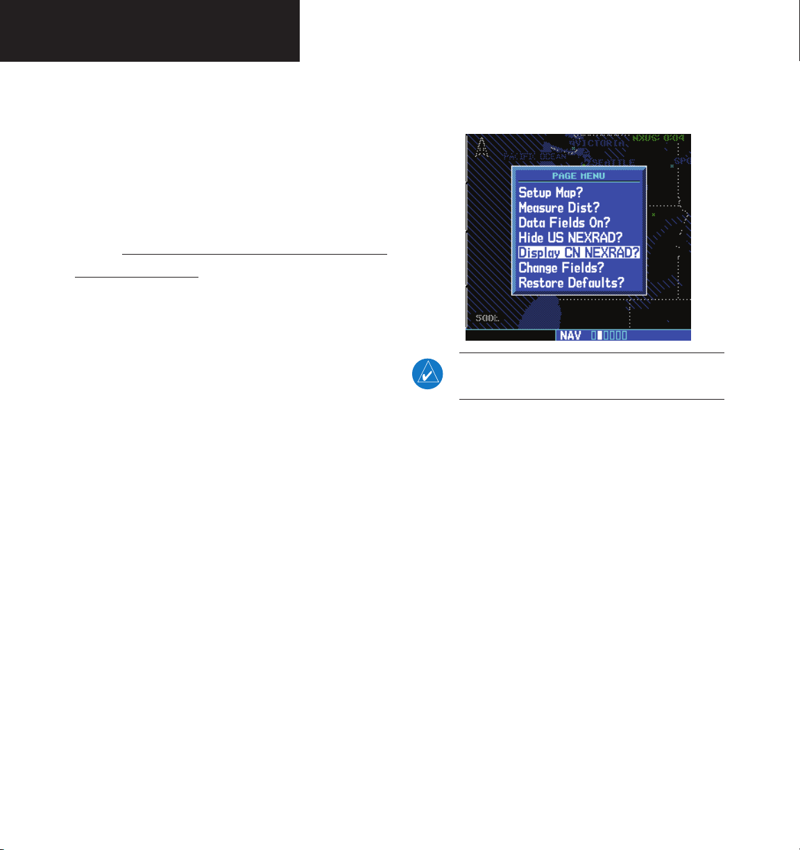
To display NEXRAD weather on the Map page:
2. If the word in the upper left corner of the
1. With the Map page (second page of the NAV
page group) displayed, press the MENU key.
The Page Menu for the Map page appears.
NEXRAD is also available on the Nav 1 page
of the 500W series.
2. Turn the large right knob to highlight “Display
3. Press the small right knob again to
US NEXRAD?” or “Display CN NEXRAD?,” and
then press ENT. (If “Hide US NEXRAD?” or
14
190-00356-30 Rev L
“Hide CN NEXRAD?) appears, NEXRAD radar
data are already enabled; just press MENU
again to exit the Page Menu.)
NOTE: US and Canadian radar may not be displayed simultaneously.
the NAV page group) displayed, look at the
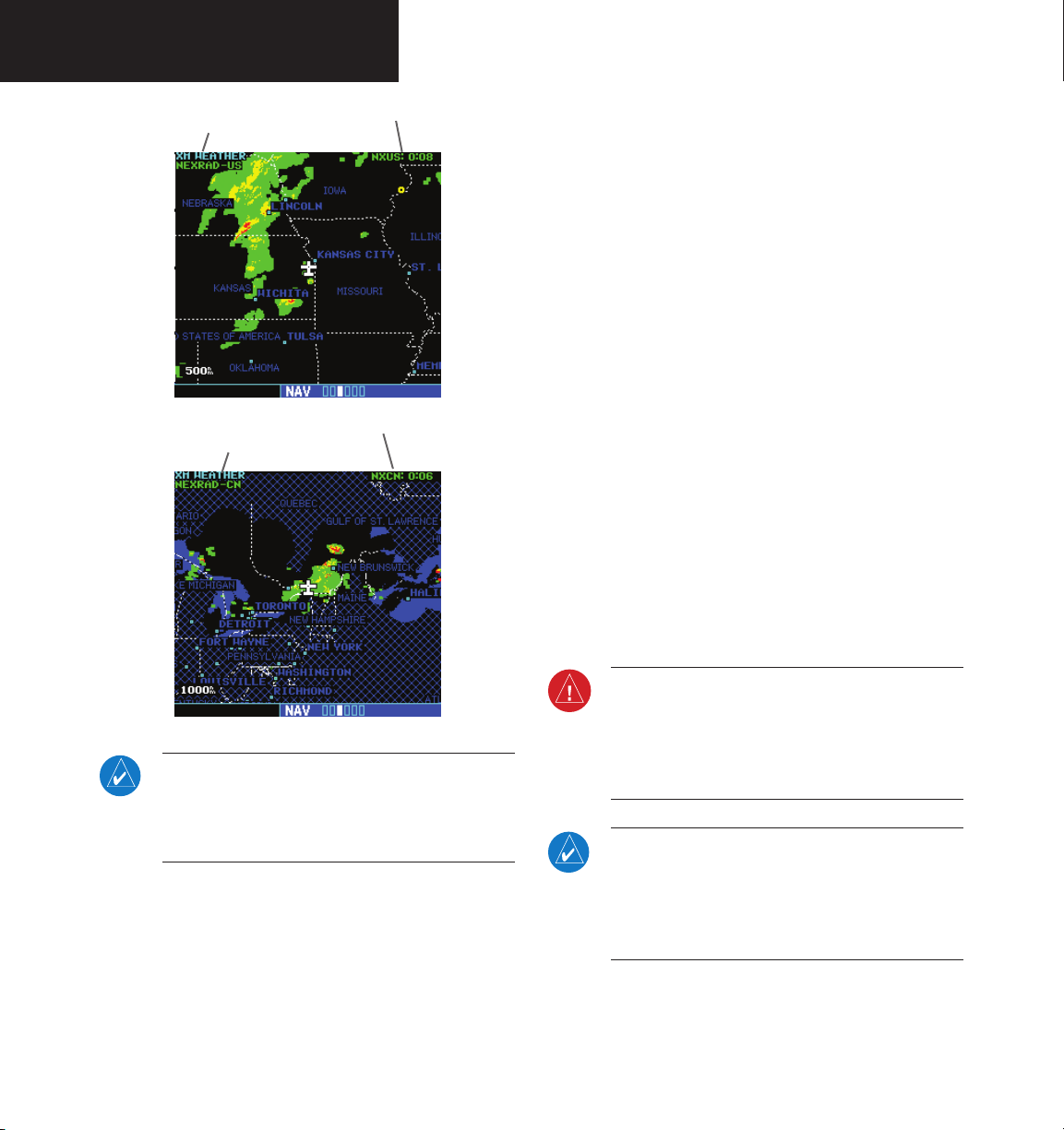
upper left corner of the page. Under the page
title (“XM Weather”) either “NEXRAD-US,”
“NEXRAD-CN,” or another weather product
appears. If the word is “NEXRAD-US” or
“NEXRAD-CN,” do nothing; NEXRAD weather
is already being displayed.
page is another weather product (rather than
“NEXRAD-US” or “NEXRAD-CN”), press the
small right (CRSR) knob to highlight that
word. Then turn the small right knob to
change to “NEXRAD-US” or “NEXRAD-CN.”
bring down the cursor (that is, to stop the
blinking highlighting of “NEXRAD-US” or
“NEXRAD-CN”) and retain the selection.
3. Press ENT to display the NEXRAD Intensity
NEXRAD U.S. and Canadian Coverage
SW Version 3.30 adds the ability to display Canadian
NEXRAD on the moving map pages and the XM Weather
page. The display has been modified to specify whether
the NEXRAD displayed is U.S. or Canadian.
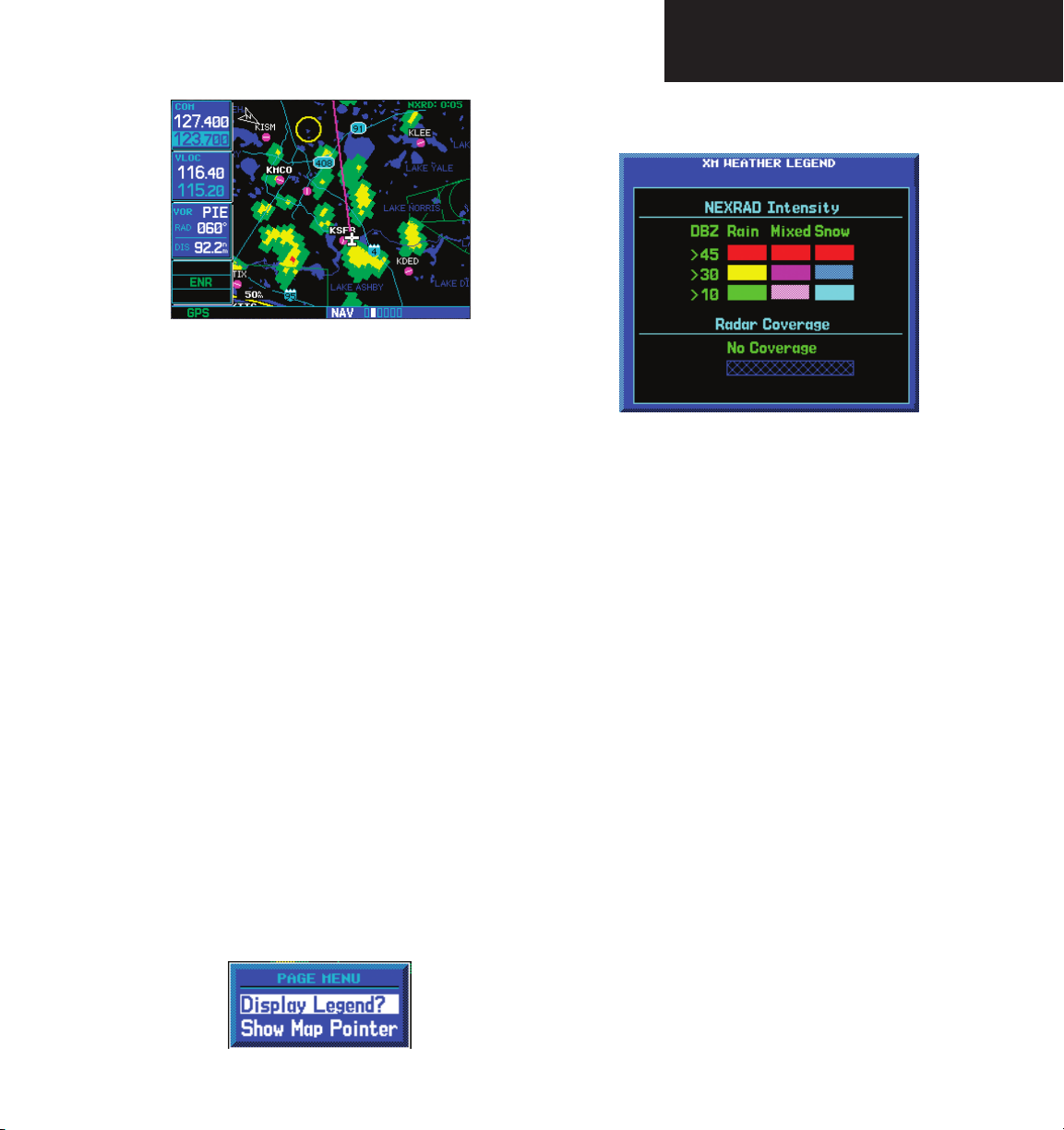
NEXRAD Intensity
4. Turn the large or small knob to scroll through
Colors are used to identify the different NEXRAD echo
intensities (reflectivity) measured in dBZ (decibels of Z).
“Reflectivity” is the amount of transmitted power returned
to the radar receiver. Reflectivity (designated by the letter
Z) covers a wide range of signals (from very weak to very
strong). So, a more convenient number for calculations
and comparison, a decibel (or logarithmic) scale (dBZ), is
used. The dBZ values increase as the strength of the signal
returned to the radar increases. There are seven gradations
for rain, two gradations for mixed rain and snow, and two
NEXRAD Abnormalities
There are possible abnormalities regarding displayed
NEXRAD images. Some, but not all, causes of abnormal
displayed information include:
• Ground Clutter
• Strobes and spurious radar data
• Sun strobes, when the radar antenna points
gradations for snow.
Part Two: Section 2
XM Weather
Legend.
the full table. Press CLR to return to the normal
view.
directly at the sun
To display the NEXRAD Intensity Legend:
1. While viewing the XM Weather page, press the
MENU key to display the Page Menu.
2. Turn the large or small knob to select “Display
legend?”
190-00356-30 Rev L
• Military aircraft deploy metallic dust which can
cause alterations in radar scans
• Interference from buildings or mountains, which
may cause shadows
• Scheduled maintenance may put a radar off-line
15
Part Two: Section 2
XM Weather
XM Weather Label and NEXRAD Source
U.S.
XM Weather Label and NEXRAD Source
Canada
NEXRAD Limitations
Certain limitations exist regarding the NEXRAD
radar displays. Some, but not all, are listed for the user’s
awareness:
• NEXRAD base reflectivity does not provide suf-
ficient information to determine cloud layers or
precipitation characteristics (hail vs. rain, etc).
• NEXRAD base reflectivity is sampled at the
minimum antenna elevation angle. An individual
NEXRAD site cannot depict high altitude storms
at close ranges, and has no information about
storms directly over the site.
• Neither NEXRAD weather data nor the age of the
NEXRAD weather data are displayed at a zoom
range of less than 10 NM. The resolution of displayed NEXRAD data is 2 kilometers. Therefore,
when zoomed in on the display, each square block
is 2 kilometers. The intensity level reflected by the
square will be the highest level sampled within
the 2 kilometer square area.
16
NOTE: The only weather products available for
Canada are Canadian NEXRAD, METARS, and
TAFs. METARS and TAFs will be shown when
available.
190-00356-30 Rev L
WARNING: Do not use data link weather information for maneuvering in, near, or around areas
of hazardous weather. Information contained
within data link weather products may not accurately depict current weather conditions.
NOTE: Do not rely solely upon data link services
to provide Temporary Flight Restriction (TFR)
information. Always confirm TFR information
through official sources such as Flight Service
Stations or Air Traffic Control.
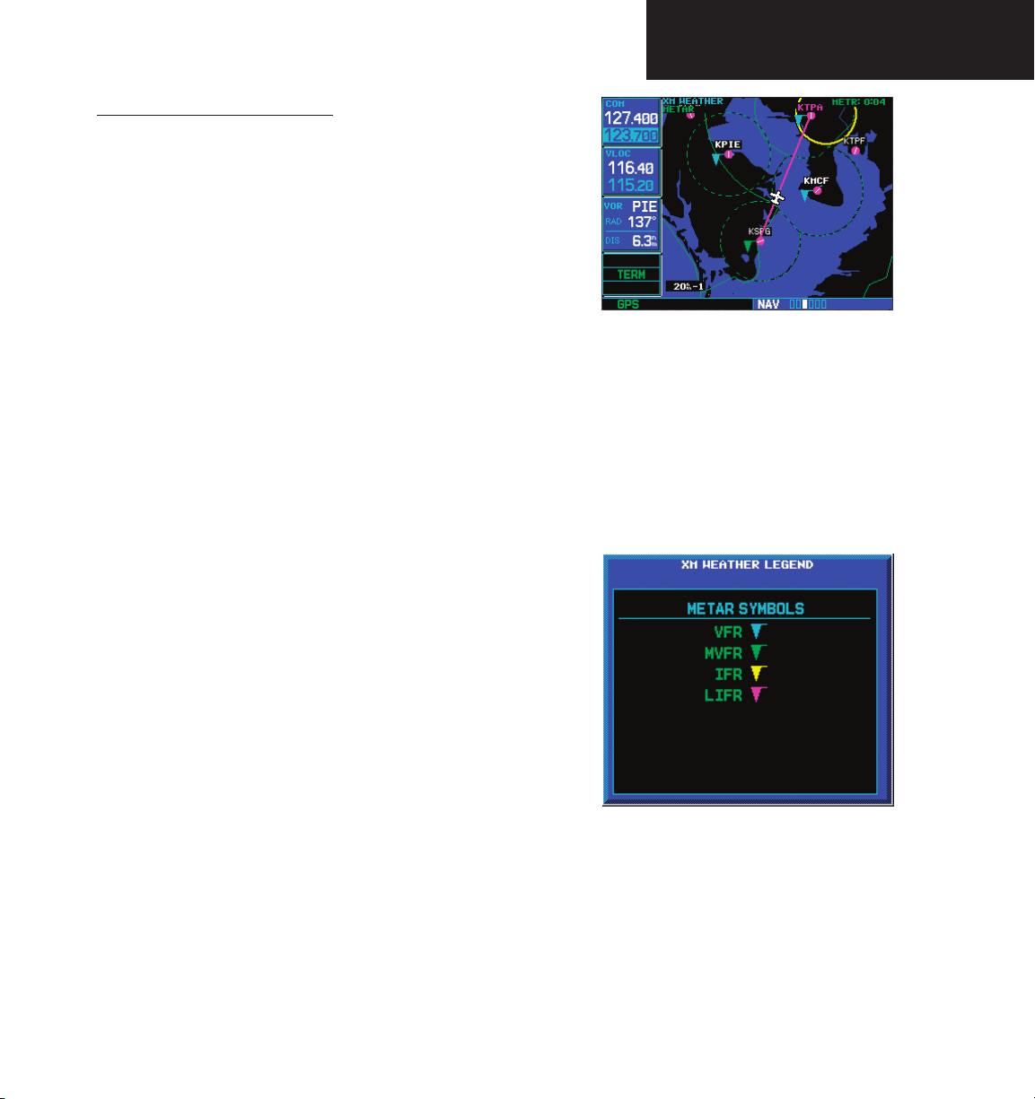
SiriusXM Weather METARs
SiriusXM Weather METARs (Meteorological Aerodrome
Reports) are available on the XM Weather page. When
enabled (that is, when “METAR” is shown in the upper
left corner of the page), airports with METAR information
above a certain severity level are marked with colored
flags on the display. Refer to the XM Weather legend for
a description of the color code. The update rate is every
12 minutes.
SW Version 5.00 adds the ability to display Canadian
METARs and TAFs.
To display METARs on the XM Weather page:
1. While viewing the XM Weather page, check
the upper left corner to see whether “METAR”
or another weather product is displayed in the
upper left corner.
2. If another weather product (rather than
“METAR”) is shown, press the small right
(CRSR) knob to highlight the product name,
such as “NEXRAD”. Turn the small right knob
to change to “METAR,” and press that small
right knob again to bring down the cursor
(stop the highlighting) and retain the “METAR”
selection.
Part Two: Section 2
XM Weather
To display the METAR Legend:
1. Press the MENU key to display the Page
Menu.
2. Turn the large or small right knob to select
“Display legend?”
3. Press ENT to display the METAR symbols
legend. Press the CLR key to remove the
METAR Symbols legend.
3. Now, colored flags will be displayed at those
airports that have METARs above a certain
severity level. (If there are no colored flags
visible, you may have to search a wider
area—zoom out with the RNG key—before
you see some METAR flags.)
190-00356-30 Rev L
17
Part Two: Section 2
XM Weather
XM Weather METAR Symbols
VFR - Ceiling > 3000 ft and
Cyan
visibility > 5 statute miles
MVFR (Marginal VFR) -
Green
Ceiling 1000 to 3000 ft, and/
or visibility 3 to 5 statute
miles
IFR - Ceiling 500 to 1000 ft,
Yellow
and/or visibility 1 to 3
statute miles
LIFR (Low IFR) - Ceiling less
Magenta
than 500 ft and/or visibility
less than 1 statute mile
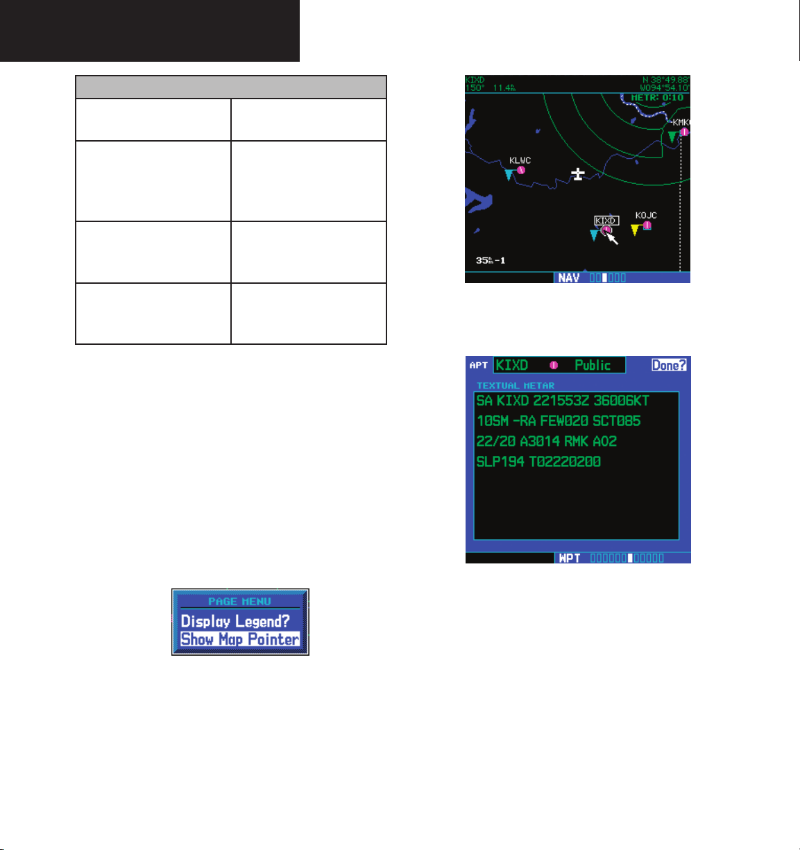
Textual METAR Page
When the GDL 69/69A is installed, a Textual METAR
page is added among the APT (airport) pages of the WPT
page group. This page can be accessed from the XM
Weather page as well as from the WPT page group.
4. Press ENT to display the METAR text. With
“Done?” highlighted, press ENT to return to
the map view.
To display Textual METARs from the Nav XM
Weather page:
1. While viewing the Nav XM Weather page, press
the MENU key to display the Page Menu.
2. Turn the large or small right knob to highlight
“Show Map Pointer?” and then press ENT.
3. Turn the large or small right knob to move
the Map Pointer to highlight an airport with a
METAR flag.
18
190-00356-30 Rev L
To view any airport’s Textual METAR page:
1. If not viewing the WPT page group, press CLR
and turn the large right knob to select the
WPT page group.
2. Turn the small right knob until the Textual
METAR page appears.

TAF Page
Aerodrome Forecast) page is inserted into the WPT page
group, immediately after the Textual METAR page.
forecast for a particular airport. The format is similar to
that used for METARS, but describes a weather forecast
rather than current weather at the particular airport.
3. To select another airport, press the small right
(CRSR) knob to highlight the airport ID (in the
“APT” field).
4. Turn the small and large right knobs to edit
the airport identifier for the desired airport.
Then, press ENT to confirm the airport name.
5. Press the small right (CRSR) knob again to
remove the cursor (that is, to stop highlighting
the APT field).
TFR Information
Textual METAR/TAF Code
The current airport weather reports on the Textual
METAR page (and the airport weather forecasts on the TAF
page, too) use a rather cryptic format originally devised for
teleprinters. You can find information about this format in
an FAA publication, Aviation Weather Formats: METAR/
TAF, which can be downloaded from the FAA Web site.
shown outlined in yellow on the NAV main page of the
500W-series and on the Map and XM Weather page of
both the 400W and 500W-series. More information about
Temporary Flight Restrictions can be seen on the TFR
Information page, which can be accessed from the Map
page or the XM Weather page.
You may see the following codes, which differ
slightly from the codes described in the FAA publication
referenced above, at the start of a METAR on the Textual
METAR page:
• SA = METAR — a standard hourly METAR
report.
• SP = SPECI — a Special Report inserted between
regular hourly METARs to provide late-breaking
weather news.
Part Two: Section 2
XM Weather
When a GDL 69/69A is installed, the TAF (Terminal
This page shows a text message giving a weather
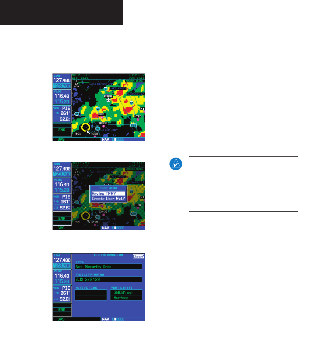
Areas with TFRs (Temporary Flight Restrictions) are
1a. With the Map page (the second page of the
NAV page group) displayed, press the small
right knob to bring up the map pointer.
or
1b. With the XM Weather page (the third page
of the NAV page group) displayed, press the
MENU key to bring up the Page Menu. Then,
turn the large right knob to highlight “Show
Map Pointer” and press ENT to bring up the
map pointer.
190-00356-30 Rev L
19
Part Two: Section 2
XM Weather
2. Turn the large and small right knobs to move
the map pointer to the yellow boundary of a
TFR region. When the map pointer is within
the TFR region, its boundary will be highlighted
with a wider yellow line.
3. Press ENT. The first item is the pop-up Page
Menu will be “Review TFR?”.
5. Press ENT when done viewing the TFR
Information page.
The fields of the TFR Information page are as follows:
• Type. A brief description of the reason for the
temporary flight restriction appears here. Some
examples of the text that might appear here are:
“Fire,” “Miscellaneous,” “National Security Area,”
“Natural Disaster,” and “Sports Event.”
• Facility/NOTAM. This filed contains a code
for the name of the FAA facility that issued the
NOTAM (Notice to Airmen) announcing the TFR,
followed by the NOTAM number. For instance,
“ZSE 6/9507” would mean NOTAM number
6/9507 from the Seattle ARTCC (KZSE).
NOTE: The full text of the NOTAM may be
obtained from a local FSS or from the FAA web
site, using the contents of this field as a reference
to locate the particular NOTAM. However, the
information shown on the TFR Information page
is sufficient to let you comply with the Temporary
Flight Restriction by avoiding the affected area.
4. Press ENT again to see the TFR Information
page.
20
190-00356-30 Rev L
• Active Time. This field is for the beginning and
ending times of the temporary flight restriction.
It may be blank, in which case the TFR is active
“until further notice.”
• Vert Limits. This field gives the upper and lower
limits of the airspace to which the TFR applies.
Part Two: Section 2
XM Weather
Lightning (LTNG)
When enabled, lightning strikes and cells are shown.
Lightning information indicates the location of cloud-toground lightning strikes. Lightning strikes are noted by
yellow plus (+) signs.
To view XM Weather Lightning Strikes:
1. While viewing the XM Weather page, check
the upper left corner to see whether “LTNG”
or another weather product is displayed.
2. If another weather product (rather than
“LTNG”) is shown, press the small right
(CRSR) knob to highlight the product name,
such as “NEXRAD”. Turn the small right knob
to change to “LTNG,” and press that small
right knob again to bring down the cursor
(stop the highlighting) and retain the “LTNG”
selection.
To view XM Weather Cell Movement:
1. While viewing the XM Weather page, check the
upper left corner to see whether “CELL MOVE”
or another weather product is displayed.
2. If another weather product (rather than “CELL
MOVE”) is shown, press the small right
(CRSR) knob to highlight the product name,
such as “NEXRAD”. Turn the small right knob
to change to “CELL MOVE,” and press that
small right knob again to bring down the
cursor (stop the highlighting) and retain the
“CELL MOVE” selection.
To view XM Weather Cell Movement details:
1. While viewing the XM Weather page with Cell
Cell Movement (CELL MOVE)
When enabled, Cell Movement shows the storm cells
2. Turn the large right knob to move the cursor
identified by the ground-based system. The movement
is depicted by an arrow. The tip of the arrow represents
where the cell is expected to be in 10 minutes from the
3. Move the cursor into the Cell Movement
time the cell location was determined. Cell Movement is
noted by a yellow box with an arrow showing reported the
direction of travel.
190-00356-30 Rev L
Movement active, activate the Map Pointer by
pressing the MENU key, highlighting “Show
Map Pointer,” and press ENT.
left and right. Turn the small right knob to
move the cursor up and down.
symbol to view details about the Cell.
21
Part Two: Section 3
XM Weather
Winds Aloft
For example, a vertically oriented wind barb with a
pennant, two long lines and a short line at its upper end
The Winds Aloft selection provides the pilot with
a graphic display of predicted winds at any one of 15
selectable altitudes. The winds at a given altitude are
selected in the Winds Aloft Alt selection. The selected
would denote a 75-knot wind blowing from the north.
To view XM Weather Winds Aloft:
1. While viewing the XM Weather page, check the
altitude is shown along with the product effective time.
Winds Aloft predictions are updated every hour and are
made available via the GDL 69/69A at a more frequent
interval.
The display includes:
2. Turn the large right knob to move the
• Wind barbs, representing wind speed, and direc-
tion
• The selected altitude
• The effective time for the prediction.
Winds Aloft are represented by meteorological symbols
known as “wind barbs”. A wind barb consists of an arrowlike line that indicates the direction in which the wind is
blowing, with marks (“barbs”) along one side of the line
to indicate wind speed. The barbed end of the symbol
points in the direction from which the wind is coming.
Barbs, which are used singly and in combinations, have
the following values:
upper left corner of the display. If a weather
product other than “WINDS” is shown, press
the small right (CRSR) knob to highlight the
product name. Turn the small right knob until
“WINDS” is displayed.
cursor down to the Altitude field, then use the
small right knob to select an altitude from
ground level up to 42,000 feet (in 3,000-foot
increments). Note that you can move up
and down the atmosphere, comparing wind
predictions at different altitudes.
• A short line: 5 knots
• A long line: 10 knots
• A pennant (triangle): 50 knots
22
190-00356-30 Rev L
Part Two: Section 3
XM Aux Pages
3. When done, press the small right (CRSR)
knob again to remove the cursor (remove
highlighting from the altitude field).
Winds Aloft Altitude
When a GDL 69 (or GDL 69A) is installed, three (or
four) pages are inserted into the 500W/500W’s AUX page
group. Here we discuss the two pages that are inserted
regardless of whether the SiriusXM Satellite Radio receiver
The Winds Aloft Altitude selection provides the pilot
with the ability to select any wind altitude from the ground
is a GDL 69 or GDL 69A:
• XM Information Page. This page contains infor-
up to 42,000 feet in 3,000 foot increments. When no data
are shown at a given altitude, the data for that altitude has
not been received. Wait for the next update. The selected
altitude is depicted below the WINDS label.
To change the XM Weather Winds Aloft altitude:
• XM Weather Timestamp Pages. These pages
1. With the “WINDS” product selected, turn the
large right knob to highlight the altitude
value.
The other AUX page, which is installed only if the
SiriusXM Satellite Radio receiver is a GDL 69A, is the XM
audio page.
XM Information Page
The XM Information page in the AUX page group is the
page you will refer to when activating your subscription to
the SiriusXM Satellite Radio services.
Section 3: XM AUX Pages
mation that you will use when activating your
SiriusXM Satellite Radio satellite radio subscription.
show timestamp data for the most recently
received XM weather data.
2. Turn the small right knob to change the
value.
3. When done, press the small right (CRSR)
knob again to remove the cursor (remove
highlighting from the altitude field).
190-00356-30 Rev L
• Audio ID. The Audio ID contains the eight-
character identification code of the XM Audio
radio built into the GDL 69A. Provide this ID to
SiriusXM Satellite Radio when activating an SiriusXM Satellite Radio audio subscription. (In the
case of a GDL 69, this field shows eight hyphens
23
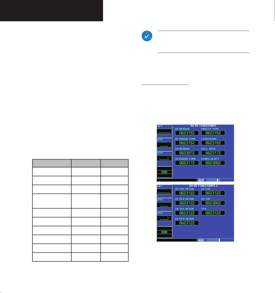
Part Two: Section 4
XM Audio
instead of an audio ID, because the GDL 69 is a
data-only receiver.)
• Audio Signal. The Audio Signal field indicates the
signal strength of the GDL 69A’s audio signal. (In
the case of a GDL 69, this field shows “antenna”
rather than a signal strength indication.)
• Data ID. The Data ID field contains the eight-
character ID code of the XM data radio built
into the GDL 69 or GDL 69A. Provide this ID
to SiriusXM Satellite Radio when activating your
XM aviation data subscription.
• Data Signal. The Data Signal field displays an
indication of the XM data signal strength.
• Service Class. Once you have activated your
SiriusXM Satellite Radio service, the Service Class
field will show the XM subscription plan you have
purchased. Typical values would be “Aviator LT” or
“Aviator.” Currently, the 400W and 500W-series
only support a subset of the Aviator LT service
from SiriusXM Satellite Radio.
NOTE: If an unrecognized service class is
detected, “Activated” will be displayed along
with a service class code.
• GDL 69 Version. This field shows the version
number of the software in your GDL 69 or GDL
69A XM radio receiver.
XM WX Timestamps
The XM WX Timestamp pages, like the XM Information
page, is added to the 400W/500W’s AUX page group
when a GDL 69/69A is installed. These pages display date/
time stamps showing when the various items of SiriusXM
Weather data were most recently downloaded.
Product Aviator LT Aviator
US NEXRAD
CN NEXRAD
Radar Coverage
Precipitation Type
(at surface)
TFRs
METARs
TAFs
US Winds Aloft
Cell Movement
Lightning
* Canadian METARs and TAFs are not available in
the Aviator LT service.
24
• •
•
• •
• •
• •
•* •
•* •
•
•
•
190-00356-30 Rev L
 Loading...