

Gardena SILENO R100Li, SILENO+ R130Li, SILENO R100LiC, SILENO+ R130LiC, SILENO+ R160Li Operator's Manual
SILENO/SILENO+
R100Li, R100LiC/R130Li, R130LiC, R160Li
Operator‘s manual
Manual_SILENO_SILENO+_151215.indd 1 2016-01-12 09:19:19

English - 1
1 Introduction and safety 3
1.1 Introduction 3
1.2 Symbols on the product 4
1.3 Symbols in the Operator’s Manual 6
1.4 Safety instructions 6
2 Presentation 10
2.1 What is what? 11
2.2 Package content 12
2.3 Function 12
3 Installation 15
3.1 Preparations 15
3.2 Installation of the charging station 16
3.3 Charging the battery 20
3.4 Installation of the boundary wire 21
3.5 Connecting the boundary wire 27
3.6 Installation of the guide wire 28
3.7 Checking the installation 31
3.8 First start-up and calibration 32
3.9 Test docking with the charging station 32
4 Use 34
4.1 Charging a at battery 34
4.2 Using the timer 35
4.3 Standby 36
4.4 Starting 37
4.5 Stopping 37
4.6 Switching off 37
4.7 Adjusting the cutting height 38
5 Control panel 39
5.1 Operation selection Start 40
5.2 Operation selection Parking 41
5.3 Main switch 41
6 Menu functions 42
6.1 Main menu 42
6.2 Menu structure 43
6.3 Timer 44
6.4 Security 47
6.5 SensorControl 48
6.6 Smart System 49
6.7 Installation 51
6.8 Settings 56
7 Garden examples 58
8 Maintenance 63
8.1 Winter storage 63
8.2 After winter storage 64
8.3 Cleaning 64
8.4 Transport and moving 66
8.5 In the event of a thunderstorm 66
8.6 Blades 66
8.7 Software update 67
8.8 Battery 68
9 Troubleshooting 69
9.1 Fault messages 69
9.2 Info messages 72
9.3 Indicator lamp in the charging station 73
9.4 Symptoms 73
9.5 Finding breaks in the loop wire 75
10 Technical Data 78
11 Guarantee terms 79
12 Environmental information 80
13 EC Declaration of Conformity 81
1157808,Gardena_R100Li-R130Li,GB_151217.indd 1 2016-01-12 09:15:32
English - 2
Serial number: _________________________
PIN code: _________________________
Product registration key: _________________________
The Product Registration Key is a valuable document and must be stored in a safe place. This key is necessary for
example to register the product on GARDENA’s website or to unlock the robotic lawnmower in the event of a lost PIN
code. The product registration key is provided in a separate document in the product packaging.
If the robotic lawnmower is stolen, it is important to notify GARDENA of this. Contact GARDENA Central Service and
provide the robotic lawnmower’s serial number and product registration key so that it can be registered as stolen in an
international database. This is an important step in the robotic lawnmower’s theft protection which reduces interest in
the buying and selling of stolen mowers.
Always have the robotic lawnmower’s serial number at hand when you contact GARDENA Central Service, as this will
provide you with faster support.
GARDENA Central Service
www.gardena.com
MEMO
1157808,Gardena_R100Li-R130Li,GB_151217.indd 2 2016-01-12 09:15:33
English - 3
INTRODUCTION AND SAFETY
1 Introduction and safety
1.1 Introduction
Congratulations on your choice of an exceptionally
high quality product. To get the best results from your
GARDENA robotic lawnmower requires knowledge of
how it works. This Operator’s Manual contains important
information about the robotic lawnmower, how it must
be installed and how to use it. The following instructions
covers all GARDENA Sileno and Sileno+ products. Within
the Sileno family you nd R100Li and R100LiC. Within
the Sileno+ family you nd R130Li, R130LiC and R160Li.
This instruction will hereby refer to the model specic
names
As a complement to this Operator’s Manual, there are
more information movies with instructions available on the
GARDENA’s website, www.gardena.com. Here you can
nd more help and guidance in its use.
Keep in mind that the operator is responsible for
accidents or hazards occuring to other people or their
property.
GARDENA has a policy of continuous product
development and therefore reserves the right to modify
the design, appearance and function of products without
prior notice.
The following system is used in the Operator’s Manual
to make it easier to use:
• Text written in italics is a text that is shown on the
robotic lawnmower’s display or is a reference to
another section in the Operator’s Manual.
• Words written in bold are one of the buttons on the
robotic lawnmower’s keypad.
• Words written in UPPERCASE and italics refer to the
position of the main switch and the different operating
modes available in the robotic lawnmower.
www.gardena.com
IMPORTANT INFORMATION
Please read the Operator’s Manual carefully
and make sure you understand the instructions
before using the robotic lawnmower. Keep
the Operator’s manual in a safe way for future
reference!
This appliance is not intended for use by
persons (including children) with reduced
physical, sensory or mental capabilities, or
lack of experience and knowledge, unless they
have been given supervision or instruction
concerning use of the appliance by a person
responsible for their safety.Children should be
supervised to ensure that they do not play with
the appliance.
1001-003
1157808,Gardena_R100Li-R130Li,GB_151217.indd 3 2016-01-12 09:15:37
English - 4
INTRODUCTION AND SAFETY
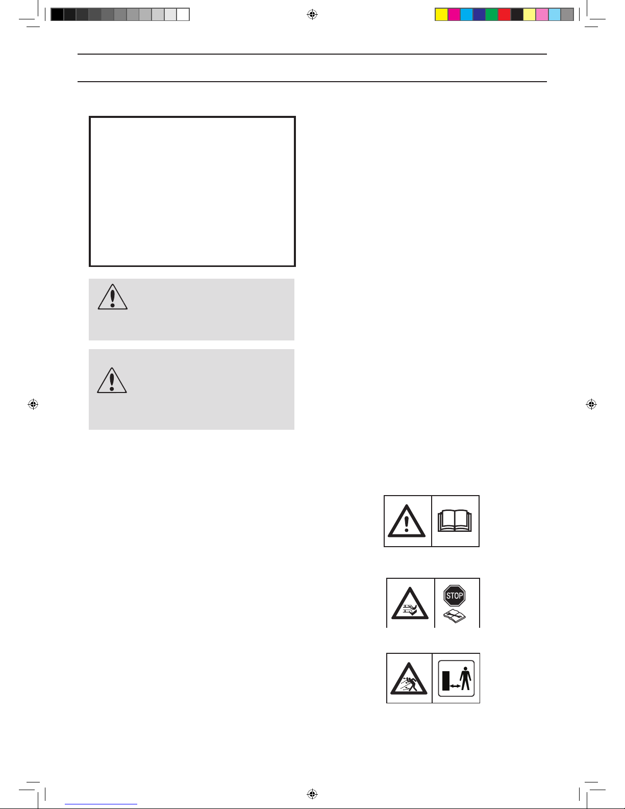
1.2 Symbols on the product
These symbols can be found on the robotic lawnmower.
Study them carefully.
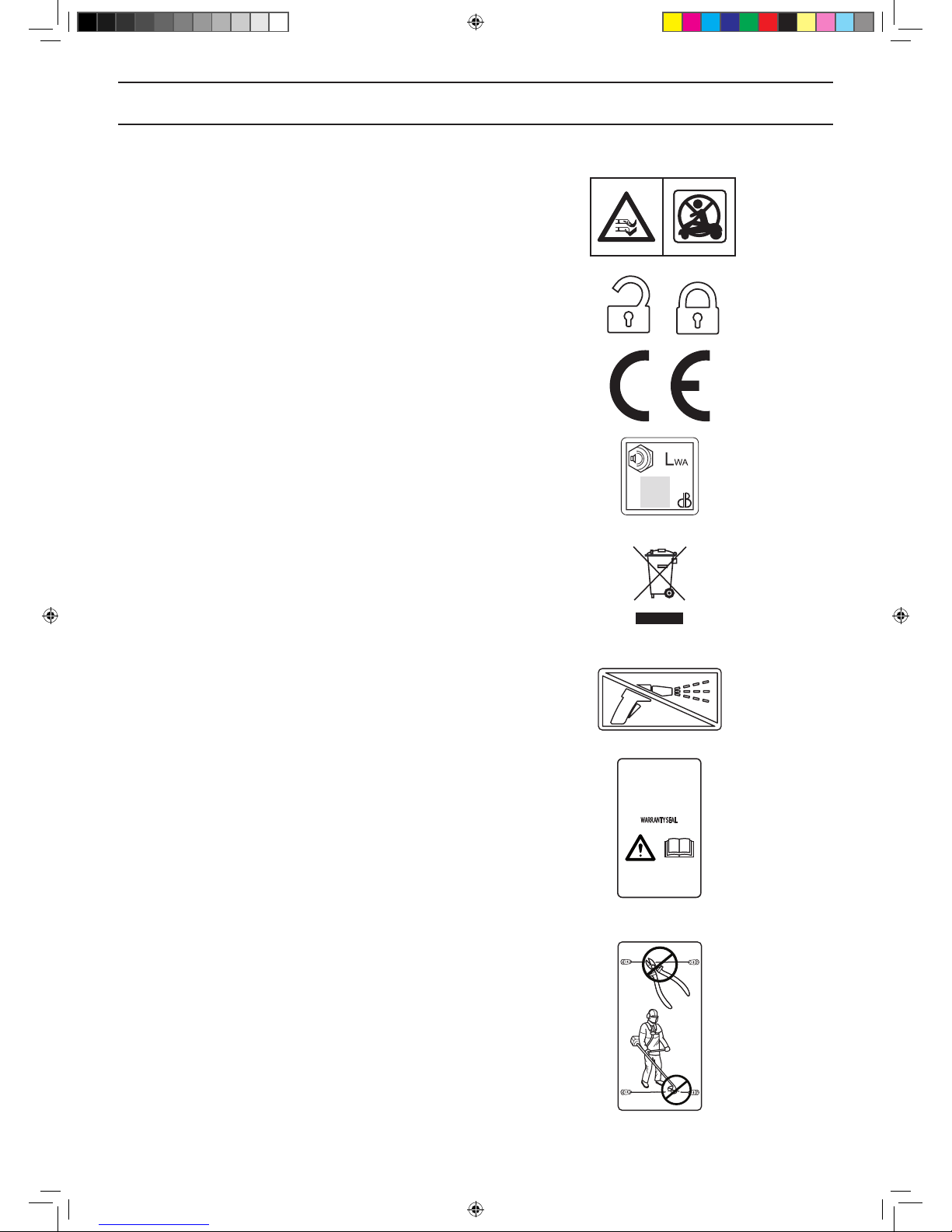
• Please read the Operator’s Manual carefully and
make sure you understand the instructions before
using the robotic lawnmower. The warnings and
safety instructions in this Operator’s Manual must be
carefully followed if the robotic lawnmower is to be
used safely and efciently.
• The robotic lawnmower can only start when the main
switch is set to 1 and the correct PIN code has been
entered. Turn the main switch to 0 before carrying out
any inspections and/or maintenance.
• Remain at a safe distance from the robotic
lawnmower when it is running. Keep your hands and
feet away from the rotating blades.
WARNING
The robotic lawnmower can be
dangerous if used incorrectly.
WARNING
Never use the robotic lawnmower
when persons, especially
children, or pets, are in the
cutting area.
IMPORTANT INFORMATION
This appliance can be used by children
aged from 8 years and above and persons
with reduced physical, sensory or mental capabilities or lack of experience and
knowledge if they have been given supervision or instruction concerning use of the
appliance in a safe way and understand
the hazards involved.
Children shall not play with the appliance.
Cleaning and user maintenance shall not
be made by children without supervision.
3018-066
3018-174
3018-173
1157808,Gardena_R100Li-R130Li,GB_151217.indd 4 2016-01-12 09:15:39
English - 5
INTRODUCTION AND SAFETY
• Never put your hands or feet close to or under the
body when the robotic lawnmower is running. Do not
ride on the robotic lawnmower.
• Lock function
• This product conforms to the applicable EC
Directives.
• Noise emission to surroundings. The product’s
emissions are set out in chapter 10, Technical data
and on the rating plate.
• It is not permitted to dispose of this product as
normal household waste when it has reached the end
of its useful life. Ensure that the product is recycled in
accordance with local legal requirements.
• Never use a high-pressure washer or even running
water to clean the robotic lawnmower.
• The chassis contains components which are
sensitive to electrostatic discharge (ESD). The
chassis is also a signicant part of the robotic
lawnmower’s design and must be resealed in
a professional manner if the product is to be used
outdoors. For this reason the chassis can only be
opened by authorized service technicians. A broken
seal can result in the entire or parts of the guarantee
no longer being valid.
• The low voltage cable must not be shortened,
extended or spliced.
• Do not use a trimmer nearby the low voltage cable.
Be careful when trimming edges where the cables
are placed.
3018-243
3032-019
6001-024
3012-1097
3012-1059
3012-665
3012-1351
3018-244
1157808,Gardena_R100Li-R130Li,GB_151217.indd 5 2016-01-12 09:15:44
English - 6
INTRODUCTION AND SAFETY
1.3 Symbols in the Operator’s Manual
These symbols can be found in the Operator’s Manual.
Study them carefully.
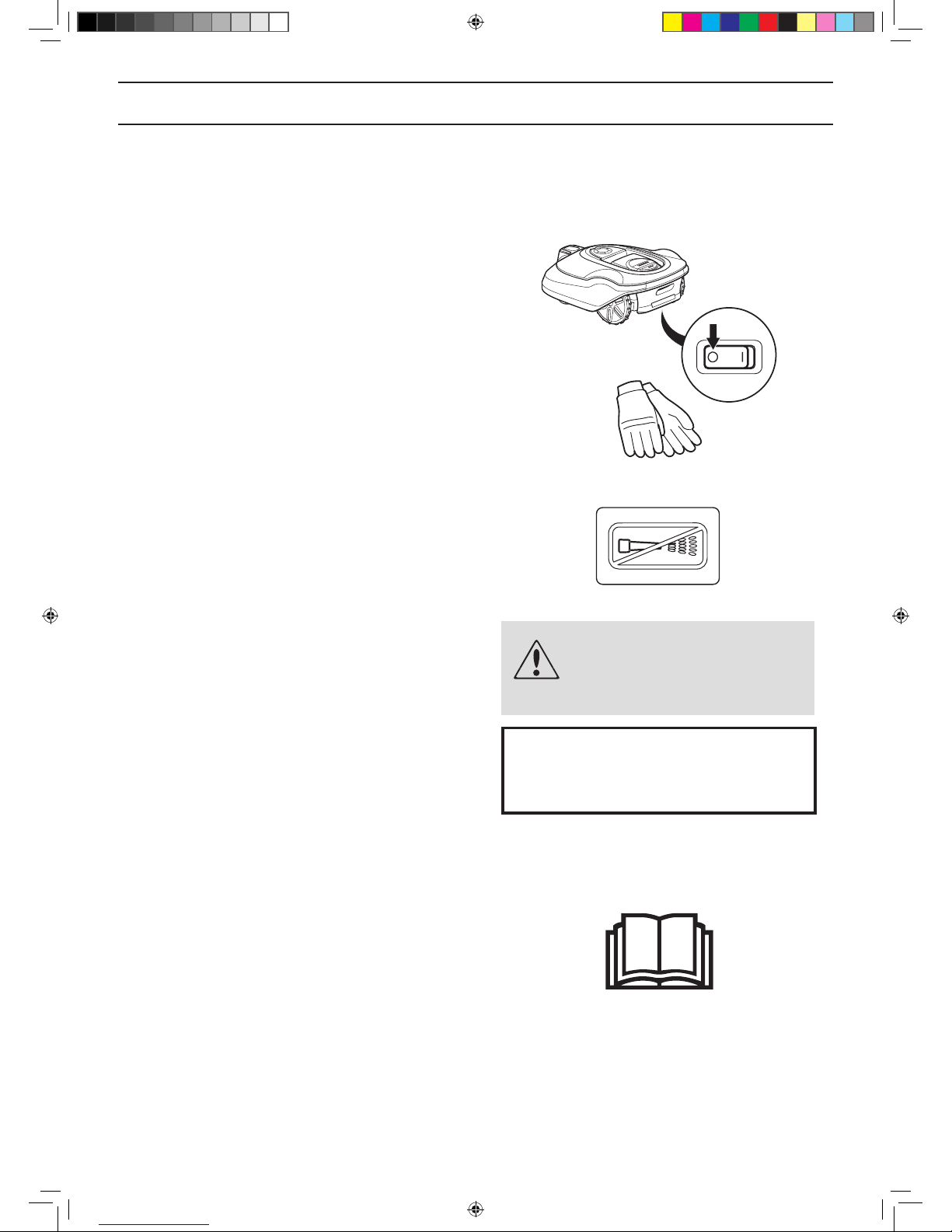
• Turn the main switch to 0 before carrying out any
inspections and/or maintenance.
• Always wear protective gloves when working with the
robotic lawnmower’s chassis.
• Never use a high-pressure washer or even running
water to clean the robotic lawnmower.
• A warning box indicates the risk of personal injury,
especially if the instructions are not followed.
• An information box indicates the risk of material
damage, especially if the instructions are not followed.
The box is also used where there is a risk of user
error.
1.4 Safety instructions
Use
• This robotic lawnmower is designed to mow grass in
open and level ground areas. It may only be used with
the equipment recommended by the manufacturer. All
other types of use are incorrect. The manufacturer’s
instructions with regard to operation/maintenance and
repair must be followed precisely.
• Use the PARK function or switch off the main switch
on the robotic lawnmower when persons, especially
children, or pets, are in the cutting area. If there are
persons, or pets, in the cutting area it is recommended
that the lawnmower be programmed for use during
hours when the area is free from persons, e.g. at night.
See 6.3 Timer on page 43.
1001-003
WARNING
Text
IMPORTANT INFORMATION
Text
3012-272
3018-062
3018-213
1157808,Gardena_R100Li-R130Li,GB_151217.indd 6 2016-01-12 09:15:46

English - 7
INTRODUCTION AND SAFETY
• The robotic lawnmower may only be operated,
maintained, and repaired by persons that are fully
conversant with its special characteristics and
safety regulations. Please read the Operator’s
Manual carefully and make sure you understand the
instructions before using the robotic lawnmower.
• It is not permitted to modify the original design of the
robotic lawnmower. All modications are made at your
own risk.
• Check that there are no stones, branches, tools,
toys or other objects on the lawn that can damage
the blades. Objects on the lawn can also lead to the
robotic lawnmower getting stuck in them and help may
be required to remove the object before the mower
can continue mowing.
• Start the robotic lawnmower according to the
instructions. When the main switch is set to 1; make
sure to keep your hands and feet away from the
rotating blades. Never put your hands and feet under
the robotic lawnmower.
• Never lift up the robotic lawnmower or carry it around
when the main switch is in position 1.
• Do not let persons who do not know how the robotic
lawnmower works and behaves use it.
• The robotic lawnmower must never be allowed
to collide with persons or other living creatures.
If a person or other living creature comes in the
lawnmower’s way it shall be stopped immediately. See
4.5 Stopping on page 35.
• Do not put anything on top of the robotic lawnmower
or its charging station.
• Do not allow the robotic lawnmower to be used with
a defective blade disc or body. Neither should it be
used with defective blades, screws, nuts or wires.
• Do not use the robotic lawnmower if the main switch
does not work.
• Always switch off the robotic lawnmower using the main
switch when the robotic lawnmower is not in use. The
robotic lawnmower can only start when the main switch
is set to 1 and the correct PIN code has been entered.
• The robotic lawnmower must never be used at the
same time as a sprinkler. Use the timer function
(see 6.3 Timer on page 43) so the mower and
sprinkler never run simultaneously.
• GARDENA does not guarantee full compatibility
between the robotic lawnmower and other types
of wireless systems such as remote controls, radio
transmitters, hearing loops, underground electric
animal fencing or similar.
• The built-in alarm is very loud. Be careful, especially if
the robotic lawnmower is handled indoors.
3018--201
3012-663
1157808,Gardena_R100Li-R130Li,GB_151217.indd 7 2016-01-12 09:15:47
English - 8
INTRODUCTION AND SAFETY
Moving
The original packaging should be used when transporting
the robotic lawnmower over long distances.
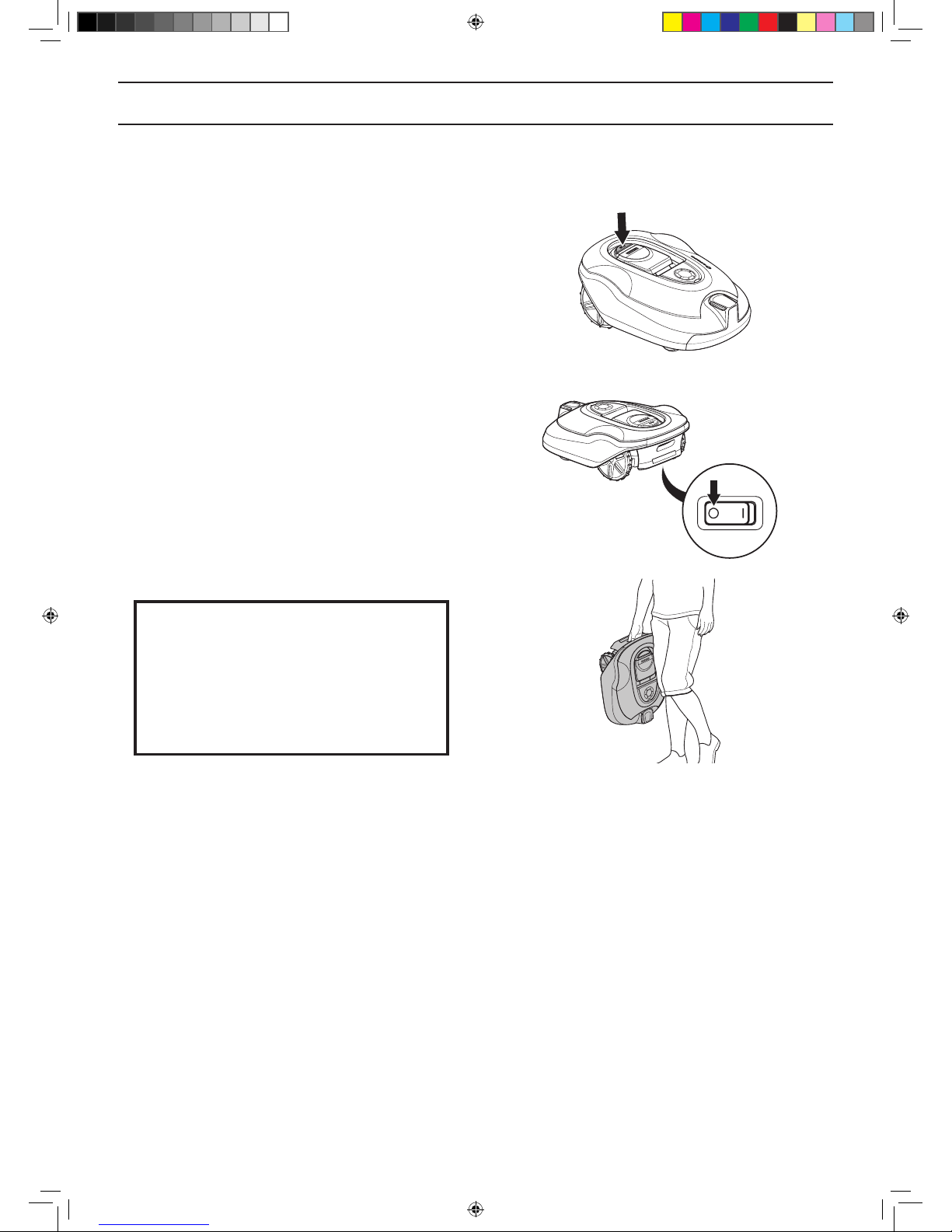
To safely move from or within the working area:
1. Press the STOP button to stop the robotic
lawnmower. If security is set to the medium or
high level (see 6.4 Security on page 47) the PIN
code has to be entered. The PIN code has four
digits and is chosen when the robotic lawnmower
is started for the rst time, see 3.8 First start-up
and calibration on page 32.
2. Set the main switch to position 0.
3. Carry the robotic lawnmower by the handle
found at the rear of the product. Carry the robotic
lawnmower with the blade disc away from the
body.
IMPORTANT INFORMATION
Do not lift the robotic lawnmower when
it is parked in the charging station. It
can damage the charging station and/or
the robotic lawnmower. Press STOP and
instead rst pull the robotic lawnmower
out of the charging station before lifting it.
3018-202
3018-213
3012-219
1157808,Gardena_R100Li-R130Li,GB_151217.indd 8 2016-01-12 09:15:49
English - 9
INTRODUCTION AND SAFETY
IMPORTANT INFORMATION
Never use a high-pressure washer or even
running water to clean the robotic lawnmower. Never use solvents for cleaning.
Maintenance
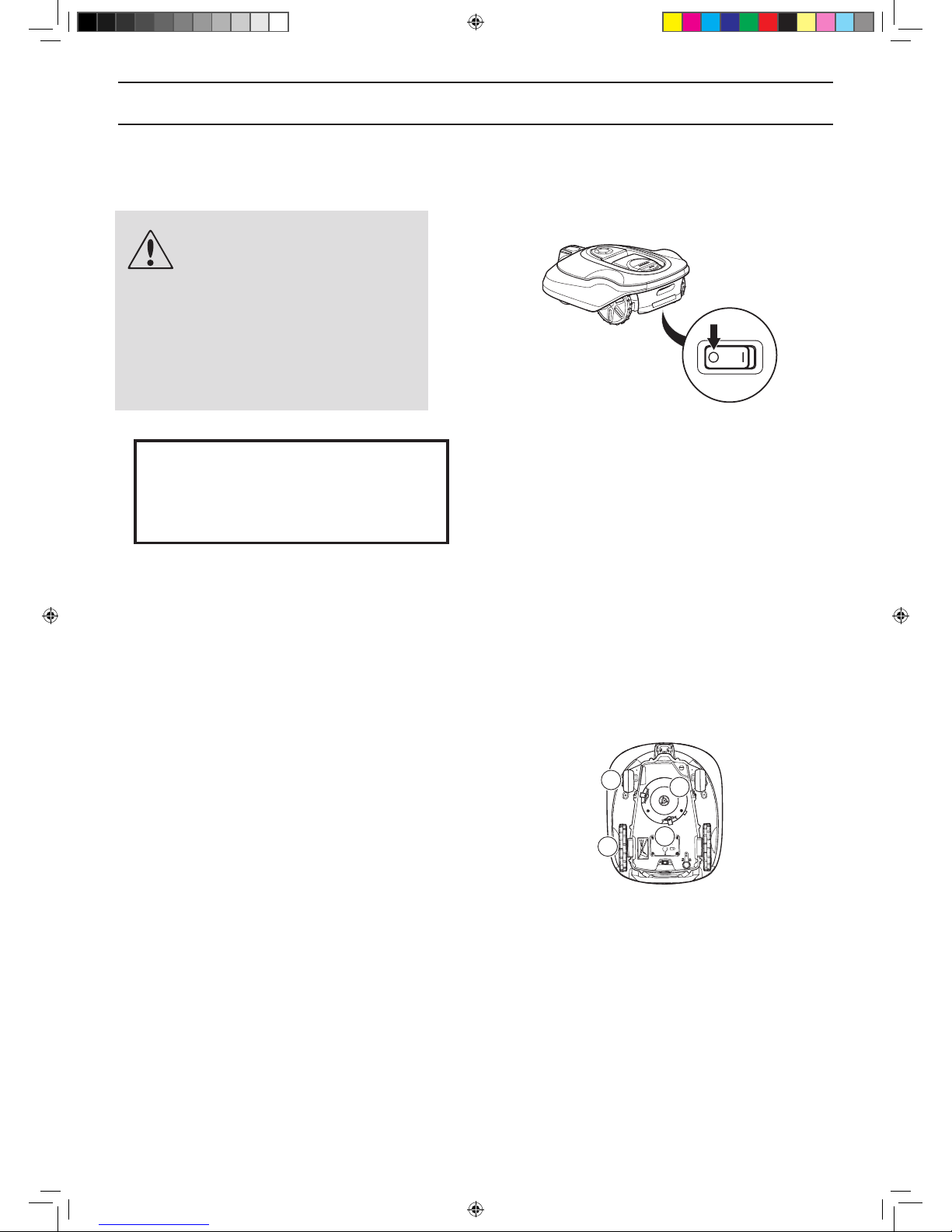
WARNING
When the robotic lawnmower
is turned upside down the main
switch must always be in the 0
position.
The main switch should be set
in the 0 position during all work
on the mower’s chassis, such as
cleaning or replacing the blades.
Inspect the robotic lawnmower each week and replace
any damaged or worn parts. The following must be carried
out in the weekly inspections:
• Clean the charging station from grass, leaves,
twigs and other objects that may impede the robotic
lawnmower from docking with the charging station.
• Set the main switch to position 0 and put on a pair of
protective gloves. Turn the robotic lawnmower upside
down. Check the following:
1. Clean the drive wheels. Grass in the drive wheels
can impact on how the lawnmower works on
slopes.
2. Clean the front wheels. Grass on the front wheels
and the front wheel axles can affect performance.
3. Clean the body, chassis and cutting system.
Grass, leaves and other objects that weigh down
the product affect performance.
4. Check that all mower blades are intact. Check
also that the mower blades can pivot freely. Even
if the mower blades are intact, they must be
replaced on a regular basis for the best mowing
result and low energy usage. Replace all blades
and screws at the same time if necessary so that
the rotating parts are kept balanced. See 8.6
Blades on page 66
3018-213
44
11
33
22
3018-226
1157808,Gardena_R100Li-R130Li,GB_151217.indd 9 2016-01-12 09:15:50
English - 10
PRESENTATION
2 Presentation
This chapter contains information that is important to be
aware of when planning the installation.
Installing a robotic lawnmower involves four main
components:
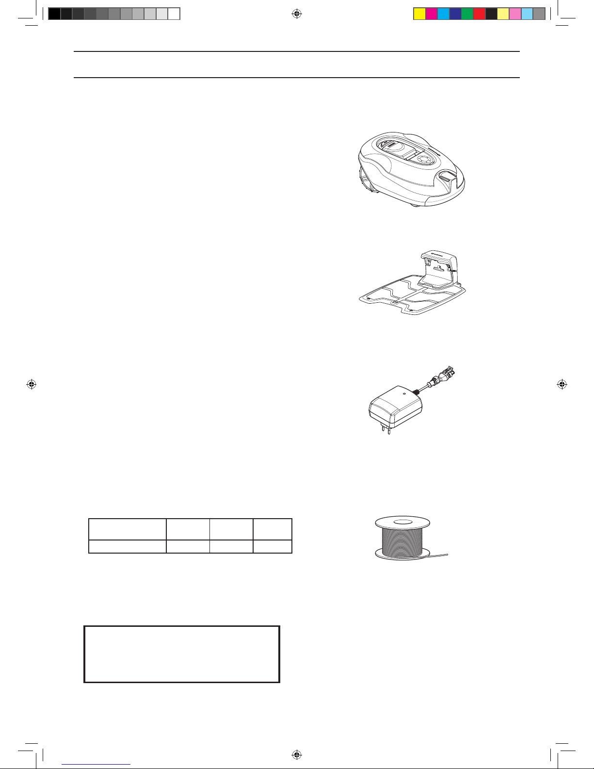
• A robotic lawnmower that mows the lawn by essentially
operating in a random pattern. The robotic lawnmower
is powered by a maintenance-free battery.
• A charging station, to where the robotic lawnmower
automatically returns when the charge level in the
battery becomes too low.The charging station has
three functions:
• To send control signals along the boundary wire.
• To send control signals along the guide wire.
• To charge the battery in the robotic lawnmower.
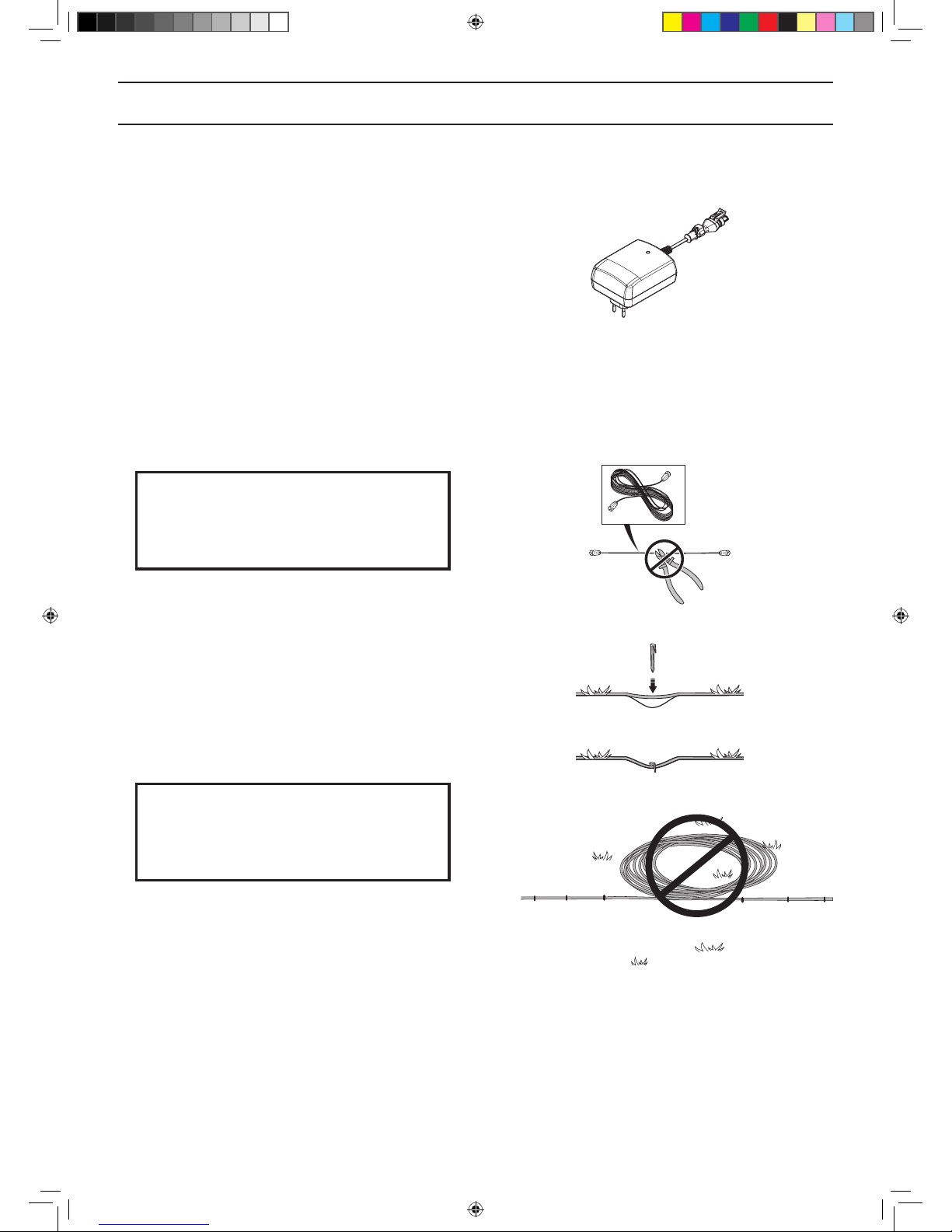
• A power supply, which is connected between the
charging station and a 100V-240V wall socket. The
power supply is connected to the wall socket and to
the charging station using a 10 m long low voltage
cable. The low voltage cable must not be shortened
or extended.
A longer low voltage cable is available as optional
accessory. Please contact GARDENA Central Service
for more information.
The appearance of the power supply may differ
depending on market.
• A loop wire, laid in a loop around the robotic
lawnmower’s working area. The loop wire is laid
around the edges of the lawn and around objects and
plants that the robotic lawnmower must not run into.
The loop wire is also used as the guide wire.
The wire supplied for the installation is:
R100Li,
R100LiC
R130Li,
R130LiC
R160Li
Wire length, m
200 250 250
If this is not sufcient, more wire can be purchased
and spliced onto the existing wire with a coupler.
The maximum permitted length for the boundary loop
is 800 m.
IMPORTANT INFORMATION
Always use genuine spare parts and accessories
3018-203
3012-1041
3012-221
3012-1352
1157808,Gardena_R100Li-R130Li,GB_151217.indd 10 2016-01-12 09:15:52
English - 11
PRESENTATION
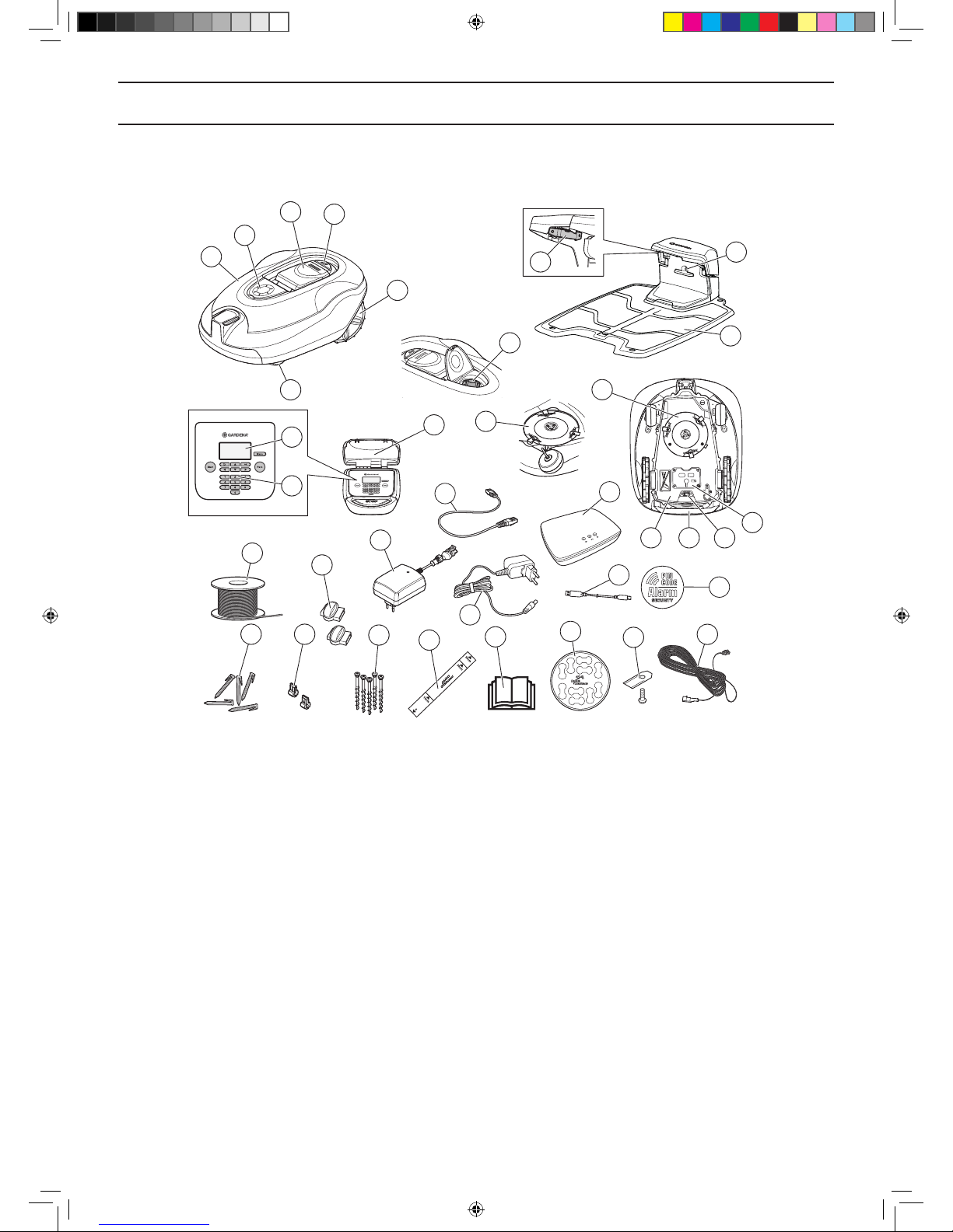
2.1 What is what?
The numbers in the illustration represent:
1. Body
2. Hatch to cutting height adjustment
3. Hatch to display and keypad
4. Stop button/Catch to open the hatch
5. Rear wheels
6. Front wheels
7. Contact strips
8. Cutting height adjustment
9. Charging station
10. LED for operation check of the charging station,
boundary wire and guide wire
11. Rating plate
12. Display
13. Keypad
14. Cutting system
15. Chassis box with electronics, battery and motors
16. Handle
17. Main switch
18. Battery cover
19. Blade disc
20. Power supply (the appearance of the power
supply may differ depending on market)
21. Loop wire for boundary loop and guide wire
22. Couplers for loop wire
23. Pegs
24. Connector for the loop wire
25. Screws for securing the charging station
26. Measurement gauge for help when installing the
boundary wire (the measurement gauge is broken
loose from the box)
27. Operator’s Manual and Quick Guide
28. Cable markers
29. Extra blades
30. Low voltage cable
31. Alarm decal
32. USB cable for Software-Updates
33. Smart System Gateway (only for GARDENA
R100LiC, R130LiC)
34. Smart System Gateway LAN-cable (only for
GARDENA R100LiC, R130LiC)
35. Smart System Gateway power supply (only for
GARDENA R100LiC, R130LiC)
3018-230
1
11
2
3
4
5
8
21
20
23 24
25
26
22
27
28
29
30
31
6
19
12
13
32
10
9
35
33
34
7
14
1715 16
18
1157808,Gardena_R100Li-R130Li,GB_151217.indd 11 2016-01-12 09:15:55
English - 12
PRESENTATION
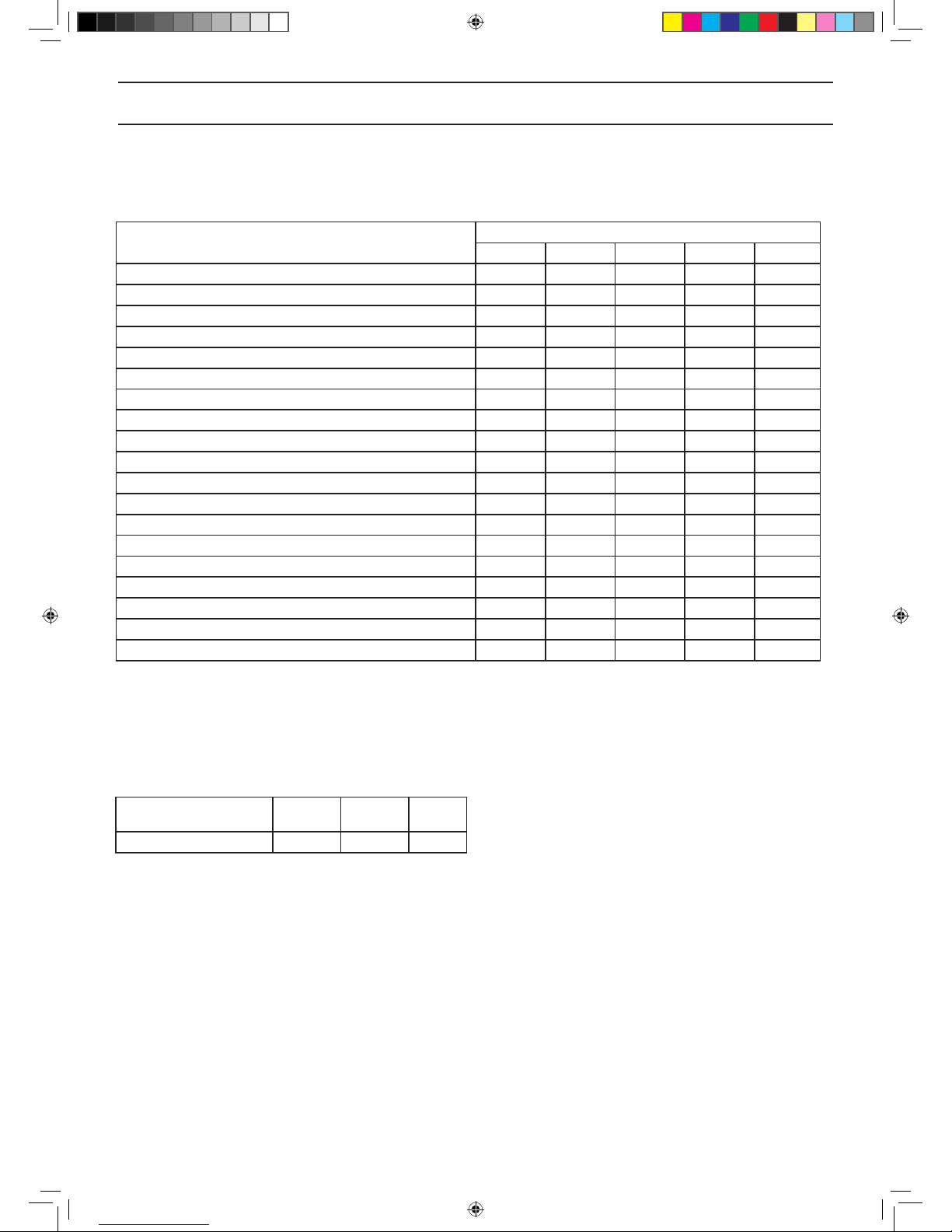
2.2 Package content
Your GARDENA robotic mower package will include the following parts.
GARDENA
R100Li R100LiC R130Li R130LiC R160Li
Robotic lawnmower √ √ √ √ √
Charging station √ √ √ √ √
Power supply √ √ √ √ √
Loop wire 200 m 200 m 250 m 250 m 250 m
Couplers 7 pcs 7 pcs 7 pcs 7 pcs 7 pcs
Pegs 400 pcs 400 pcs 400 pcs 400 pcs 400 pcs
Connectors 5 pcs 5 pcs 5 pcs 5 pcs 5 pcs
Charging station screws 5 pcs 5 pcs 5 pcs 5 pcs 5 pcs
Allen key √ √ √ √ √
Measurement gauge √ √ √ √ √
Low voltage cable √ √ √ √ √
Operator´s Manual and Quick Guide √ √ √ √ √
Cable markers √ √ √ √ √
Extra blades 9 pcs 9 pcs 9 pcs 9 pcs 9 pcs
Alarm decal √ √ √ √ √
USB cable for Software-Updates √ √ √ √ √
Smart System Gateway √ √
Smart System Gateway LAN-cable √ √
Smart System Gateway power supply √ √
2.3 Function
Capacity
The robotic lawnmower is recommended for lawns up to:
R100Li,
R100LiC
R130Li,
R130LiC R160Li
Lawn area, m
2
1000 1300 1600
How big an area the robotic lawnmower can keep cut
depends primarily on the condition of the blades and the
type, growth and moisture of the grass. The shape of the
garden is also signicant. If the garden mainly consists of
open lawn areas, the robotic lawnmower can mow more
per hour than if the garden consists of several small lawns
separated by trees, ower beds and passages.
A fully charged robotic lawnmower mows for 60 to 80
minutes, depending on the age of the battery and how
thick the grass is. Then the robotic lawnmower will
charge for 60 to 70 minutes. The charging time can
vary depending on, among other factors, the ambient
temperature.
1157808,Gardena_R100Li-R130Li,GB_151217.indd 12 2016-01-12 09:15:56
English - 13
PRESENTATION
Mowing technique
The cutting system in the robotic lawnmower is based
on an efcient and energy saving principle. Unlike many
standard lawnmowers, the robotic lawnmower cuts the
grass instead of knocking it off.
We recommend you allow the robotic lawnmower to
mainly mow in dry weather to obtain the best possible
result. GARDENA’s robotic lawnmowers can also mow
in the rain, however, wet grass easily sticks on the robotic
lawnmower and there is a greater risk of slipping on steep
slopes.
The blades must be in good condition to obtain the best
mowing result. In order to keep the blades sharp for as
long as possible it is important to keep the lawn free
from branches, small stones and other objects which
can damage the blades.
Replace the blades regularly for the best mowing result.
It is very easy to replace the blades.See 8.6 Blades on
page 66.
Working method
The robotic lawnmower automatically mows the lawn.
It continuously alternates between mowing and charging.
The robotic lawnmower starts to search for the charging
station when the battery charge becomes too low. The
robotic lawnmower does not mow when it is searching for
the charging station.
When the robotic lawnmower is searching for the
charging station, it rst searches irregulary for the guide
wire. Then it follows the guide wire to the charging
station.
When the battery is fully charged, the robotic lawnmower
will leave the charging station and start mowing in a
predened area in the garden. You might have to set
manual exit settings to make sure that the lawn will be cut
evenly, see 6.7 “Installation” on page 51.
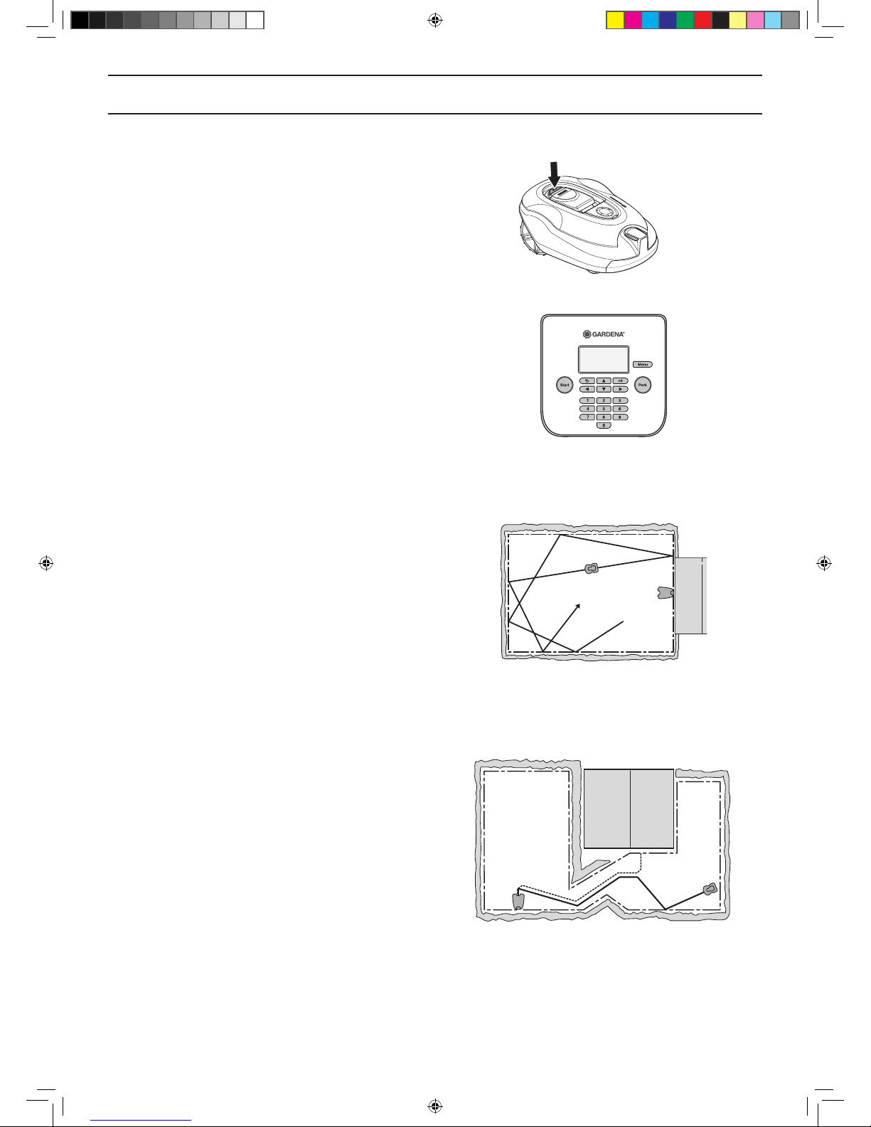
When the robotic lawnmower body hits an obstacle, the
robotic lawnmower reverses and selects a new direction.
Sensors at the front and back will sense when the robotic
lawnmower is approaching the boundary wire. The
robotic lawnmower travels up to 32 centimetres beyond
the wire before it turns around.
3023-003
3018-204
3020-002
1157808,Gardena_R100Li-R130Li,GB_151217.indd 13 2016-01-12 09:15:57
English - 14
PRESENTATION
The STOP button on the top of the robotic lawnmower
is mainly used to stop the robotic lawnmower when it’s
running. When the STOP button is pressed a hatch
opens, behind which there is a control panel. The STOP
button remains pressed in until the hatch is closed again.
This together with the START button acts as a start
inhibitor.
The control panel on the top of the robotic lawnmower is
where you manage all the robotic lawnmower settings.
When the main switch is set to 1 for the rst time,
a start-up sequence begins which includes a number
of important basic settings. See 3.8 First start-up and
calibration on page 32.
Movement pattern
The movement pattern of the robotic lawnmower is
random and is determined by the robotic lawnmower
itself. A movement pattern is never repeated. With this
cutting system the lawn is mown very evenly without any
mowing lines from the robotic lawnmower.
Search method
The robotic lawnmower operates irregularly until it
reaches the guide wire. Then the robotic lawnmower
follows the guide wire to the charging station.
The guide wire is a wire that is laid from the charging
station towards, for instance, a remote part of the working
area or through a narrow passage to be then connected
with the boundary loop. See 3.6 Installation of the guide
wire on page 28.
3018-202
3018-239
3023-012
3023-013
1157808,Gardena_R100Li-R130Li,GB_151217.indd 14 2016-01-12 09:15:59
English - 15
INSTALLATION
3 Installation
This chapter describes how to install the robotic
lawnmower. Before starting the installation read the
previous chapter 2. Presentation.
Read also through this entire chapter before beginning
the installation. How the installation is done also affects
how well the robotic lawnmower works. It is therefore
important to plan the installation carefully.
Planning is simplied if you make a sketch of the working
area, including all obstacles. This makes it easier to see
the ideal positions for the charging station, the boundary
wire and the guide wire. Draw on the sketch where the
boundary and guide wires should be routed.
Ssee 7 Garden examples on page 58 for installation
examples.
Visit also www.gardena.com for further descriptions and
tips regarding installation.
Carry out the installation as outlined in the
following steps:
3.1 Preparations
3.2 Installation of the charging station
3.3 Charging the battery
3.4 Installation of the boundary wire
3.5 Connecting the boundary wire
3.6 Installation of the guide wire
3.7 Checking the installation
3.8 First start-up and calibration
3.9 Test docking with the charging station
The charging station, boundary loop and guide wire must
be connected to be able to carry out a complete start-up.
3.1 Preparations
1. If the lawn in the working area is longer than
10 cm mow it using a standard lawnmower.
Then collect the grass.
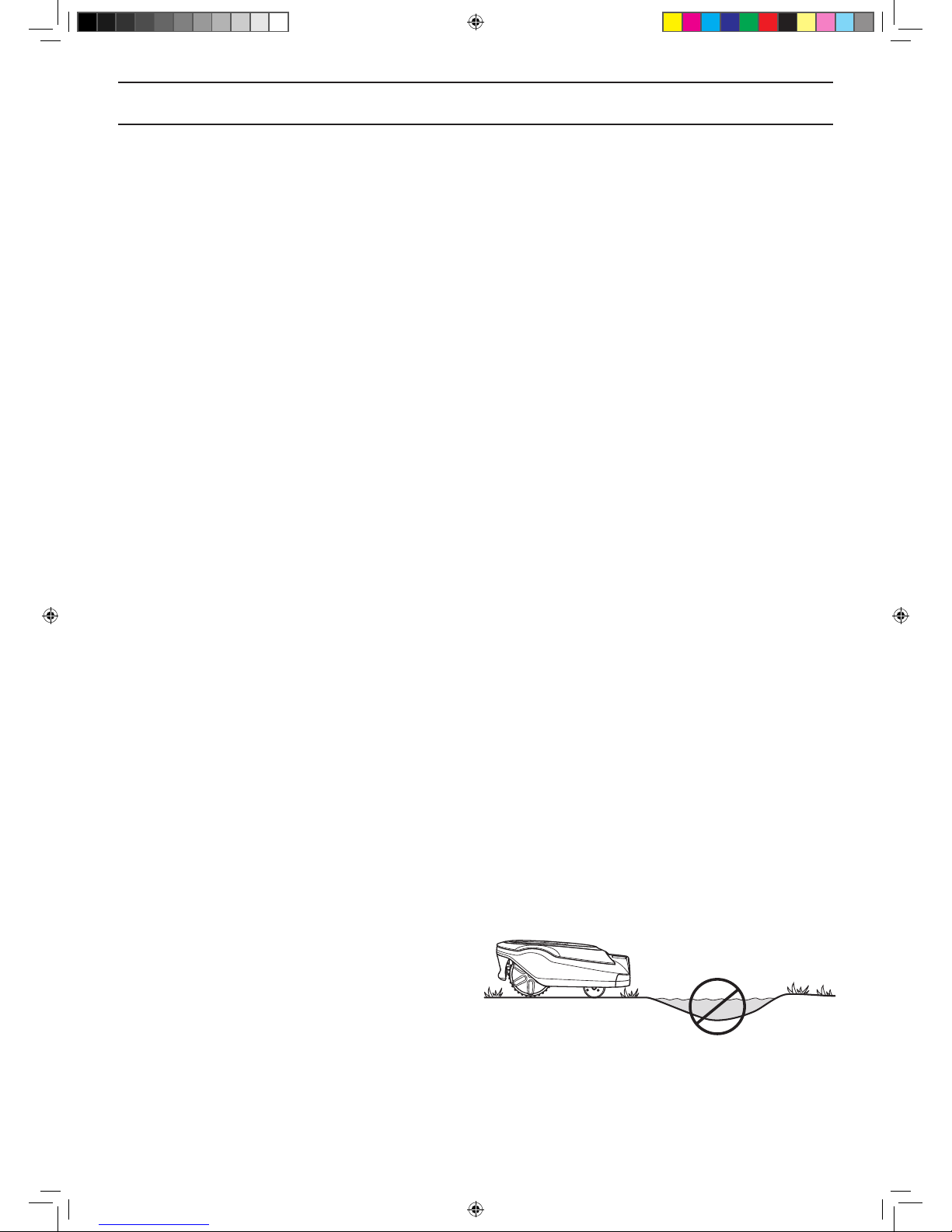
2. Fill in holes and hollows to stop rainwater forming
pools of water. The product may be damaged if it
is operated in pools of water. See 11 Guarantee
terms on page 79.
3. Read carefully through all the steps before the
installation.
3018-212
1157808,Gardena_R100Li-R130Li,GB_151217.indd 15 2016-01-12 09:16:00
English - 16
INSTALLATION
4. Check that all parts for the installation are
included. The numbers in brackets refer to the
component illustration. See 2.1 What is what? on
page 11.
• Robotic lawnmower
• Charging station (10)
• Loop wire for boundary loop and
guide wire (22)
• Power supply (21)
• Low voltage cable (30)
• Pegs (23)
• Connectors for the loop wire (24)
• Screws for the charging station (25)
• Measurement gauge (26)
• Couplers for the loop wire (22)
• Cable markers (28)
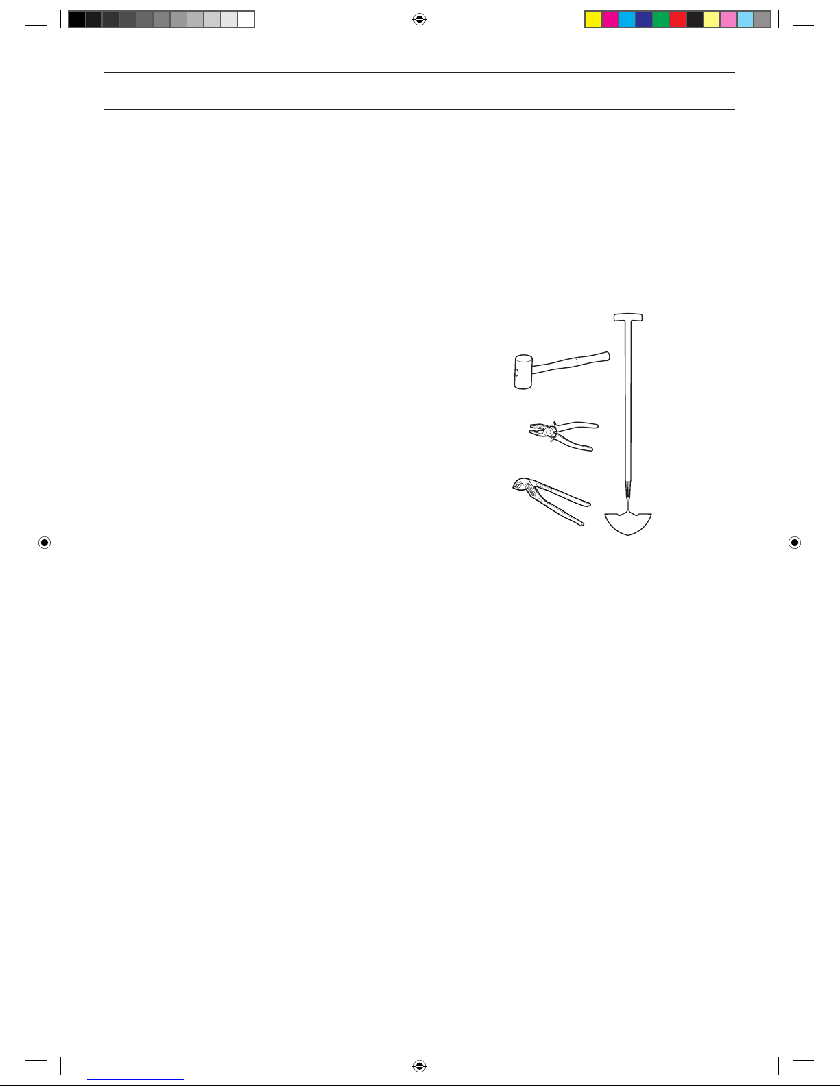
During installation you will also need:
• Hammer/plastic mallet (to simplify putting the
pegs in the ground).
• Combination pliers for cutting the boundary wire
and pressing the connectors together.
• Polygrip (for pressing the couplers together).
• Edge cutter/straight spade if the boundary wire
must be buried.
3.2 Installation of the charging station
Best charging station location
Take the following aspects into consideration when
identifying the best location for the charging station:
• Allow for at least 3 metres of free space in front of
the charging station.
• It must be close to a wall socket. The supplied low
voltage cable is 10 metres long.
• A level surface free from sharp objects to place
the charging station on.
• Protection from water spray for instance from
irrigation.
• Protection from direct sunlight.
• Possible requirement to keep the charging station
out of sight for outsiders.
3012-1311
1157808,Gardena_R100Li-R130Li,GB_151217.indd 16 2016-01-12 09:16:01
English - 17
INSTALLATION
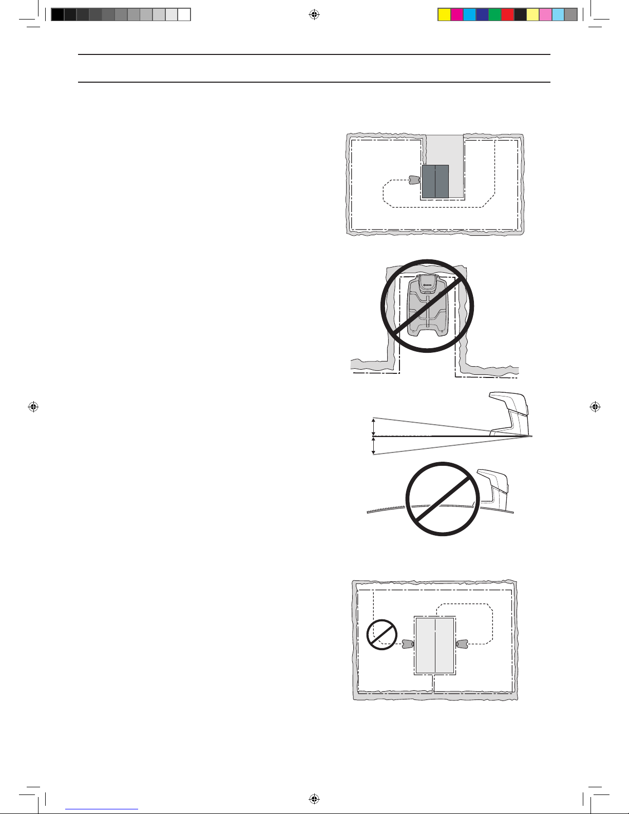
The charging station must be positioned with a great deal
of free space in front of it (at least 3 metres). It should
also be centrally placed in the working area to make it
easier for the robotic lawnmower to reach all areas in the
working area.
Do not put the charging station in conned spaces in the
working area. This can make it difcult for the robotic
mower to nd the charging station.
he charging station must be positioned on relatively level
ground. The front end of the charging station must be a
maximum of 5 cm higher or lower than the back end.
The charging station must not be positioned in a way that
can bend its base plate.
The charging station should not be placed on an island as
this limits the laying of the guide wire in an optimal way. If
the charging station has to be installed on an island, the
guide wire also has to be connected to the island. See the
illustration. Read more about islands in the 3.4 Installation
of the boundary wire chapter.
Max 5 cm
Max 5 cm
3012-1312
3012-1053
3023-003
3018-238
3023-004
1157808,Gardena_R100Li-R130Li,GB_151217.indd 17 2016-01-12 09:16:03
English - 18
INSTALLATION
Connecting the power supply
Take the following into consideration when planning
where to place the power supply:
• Close to the charging station
• Protection from rain
• Protection from direct sunlight
If the power supply is connected to an electrical socket
outdoors, this must be approved for outdoor use.
The low voltage cable for the power supply is 10 metres
long, and may not be shortened or extended.
It is not allowed to connect the power supply directly to
the charging station. The low voltage cable must always
be used.
IMPORTANT INFORMATION
The low voltage cable must not under any
circumstances be shortened or extended.
It is possible to let the low voltage cable cross the
working area. The low voltage cable must be stapled
down or buried.
Make sure the low voltage cable is laid along the ground
and secured with pegs. The cable must lie close to the
ground so as not to be cut before the grass roots have
grown over it.
IMPORTANT INFORMATION
Place the low voltage cable so that the
blades on the blade disc can never come
in contact with it.
The power supply must be placed where it is well
ventilated and is not exposed to direct sunlight. The
power supply must be placed under a roof.
It is recommended to use a ground fault circuit interrupter
when connecting the power supply to the wall socket.
The power supply must be mounted on a vertical surface,
such as a wall or a fence.
3018-069
3018-085
3012-1352
3012-281
1157808,Gardena_R100Li-R130Li,GB_151217.indd 18 2016-01-12 09:16:05
English - 19
INSTALLATION
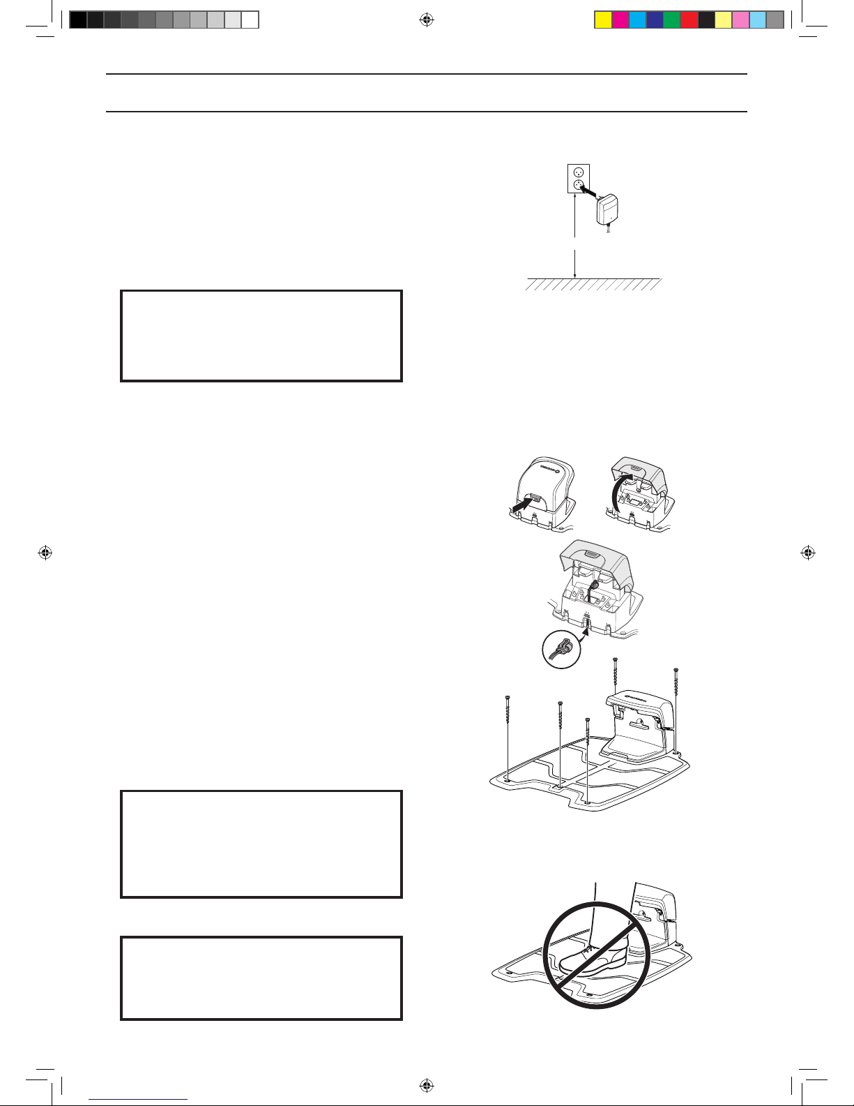
Do not, under any circumstances, mount the power supply
at a height where there is a risk it can be submerged in
water (at least 30 cm from the ground). It is not permitted
to place the power supply on the ground.
Never connect the power supply to a outlet if plug or cord
is damaged. Damaged or entangled cord increase the risk
of electric shock.
IMPORTANT INFORMATION
Use the power supply’s plug to disconnect
the charging station, for instance before
cleaning or repairing the loop wire.
Installing and connecting the charging station
1. Position the charging station in a suitable spot.
2. Tilt the protective cover on the charging station
forward and connect the low voltage cable to the
charging station.
3. Connect the power supply’s power cable to a 100240 V wall socket.
4. Attach the charging station to the ground using the
supplied screws. Ensure the screws are screwed
all the way down in the countersink. If the charging
station is placed against a wall, it is best to wait
before securing the charging station to the ground
until after all the wires have been connected.
IMPORTANT INFORMATION
It is not permitted to make new holes
in the charging station’s plate. Only the
existing holes may be used to secure the
base plate to the ground.
IMPORTANT INFORMATION
Do not tread or walk on the charging
station’s plate.
min 30cm/12”
3012-1344
3018-220
3018-221
3018-235
1157808,Gardena_R100Li-R130Li,GB_151217.indd 19 2016-01-12 09:16:07
English - 20
INSTALLATION
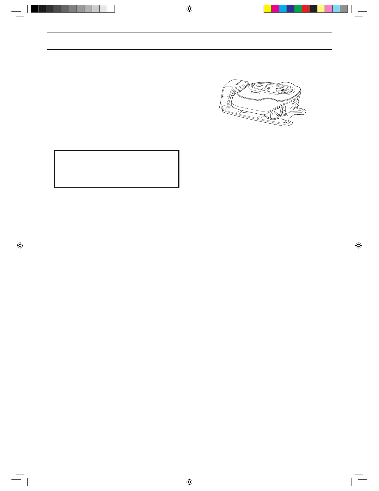
3.3 Charging the battery
As soon as the charging station is connected, it is
possible to charge the robotic lawnmower. Set the main
switch to position 1.
Place the robotic lawnmower in the charging station to
charge the battery while the boundary and guide wires
are being laid.
If the battery is at , it takes around 80 to 100 minutes to
fully charge it.
IMPORTANT INFORMATION
The robotic lawnmower cannot be used
before the installation is complete.
3018-217
1157808,Gardena_R100Li-R130Li,GB_151217.indd 20 2016-01-12 09:16:08
English - 21
INSTALLATION
3.4 Installation of the boundary wire
Ensure correct installation of the boundary wire according to the instruction
The boundary wire can be installed in one of the following ways:
• Secure the wire to the ground with pegs.
It is preferable to staple down the boundary wire if you want to make adjustments to the boundary loop during
the rst few weeks of operation. After a few weeks the grass will have grown over the wire making it no longer
visible. Use a hammer/plastic mallet and the pegs supplied when carrying out the installation.
• Bury the wire.
It is preferable to bury the boundary wire if you want to dethatch or aerate the lawn. If necessary, both methods
can be combined so one part of the boundary wire is pegged down and the remainder is buried. The wire can
be buried for instance using an edge cutter or a straight spade. Make sure to lay the boundary wire at least 1
cm and a maximum of 20 cm in the ground.
Plan where to lay the boundary wire
The boundary wire must be laid so that:
• The wire forms a loop around the working area for the robotic lawnmower. Only original boundary wire must be
used. It is specially designed to resist dampness from the soil that could otherwise easily damage the wires.
• The robotic lawnmower is never more than 35 metres from the wire at any point in the entire working area.
• The wire is no more than 800 metres long.
• About 20 cm of extra wire is available to which the guide wire will be connected later. See 3.6 Installation of the
guide wire on page 28 .
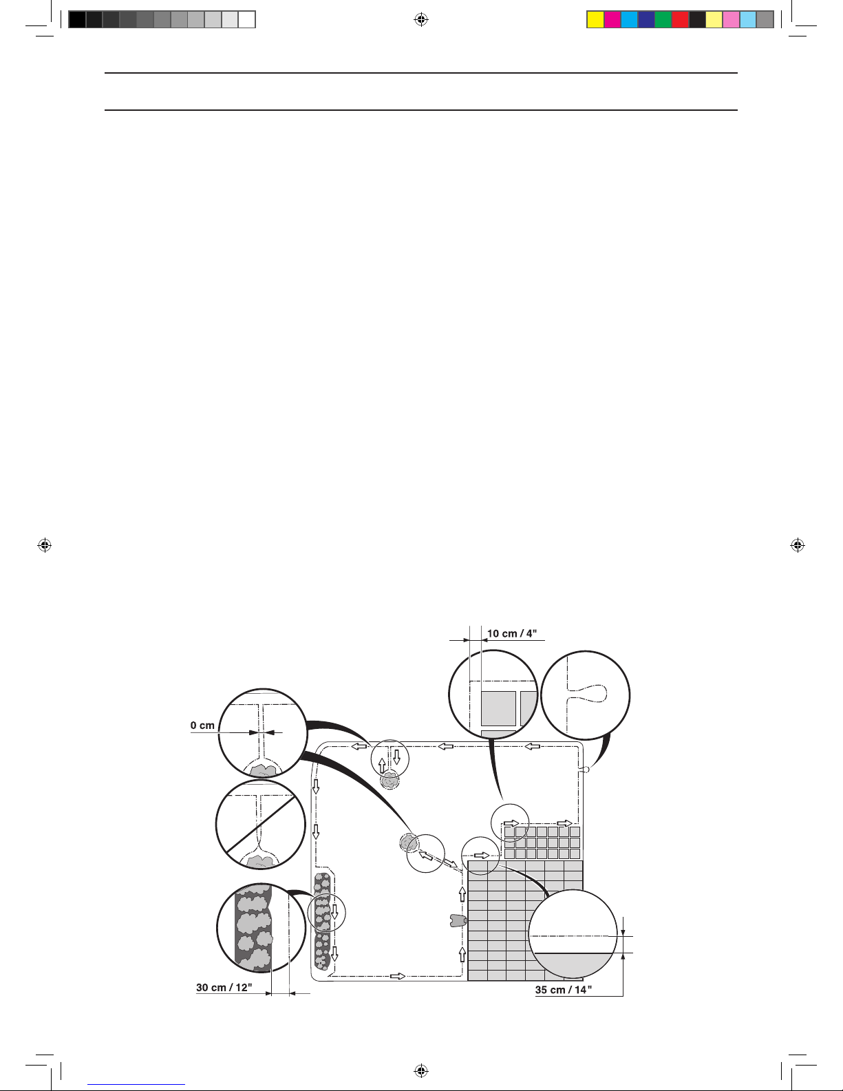
Depending on what the working area is adjacent to, the boundary wire must be laid at different distances from
obstacles. The illustration below shows how the boundary wire must be laid around the working area and around
obstacles. Use the supplied measurement gauge to obtain the correct distance. See 2.1 What is what? on page 11.
3023-031
1157808,Gardena_R100Li-R130Li,GB_151217.indd 21 2016-01-12 09:16:08
English - 22
INSTALLATION
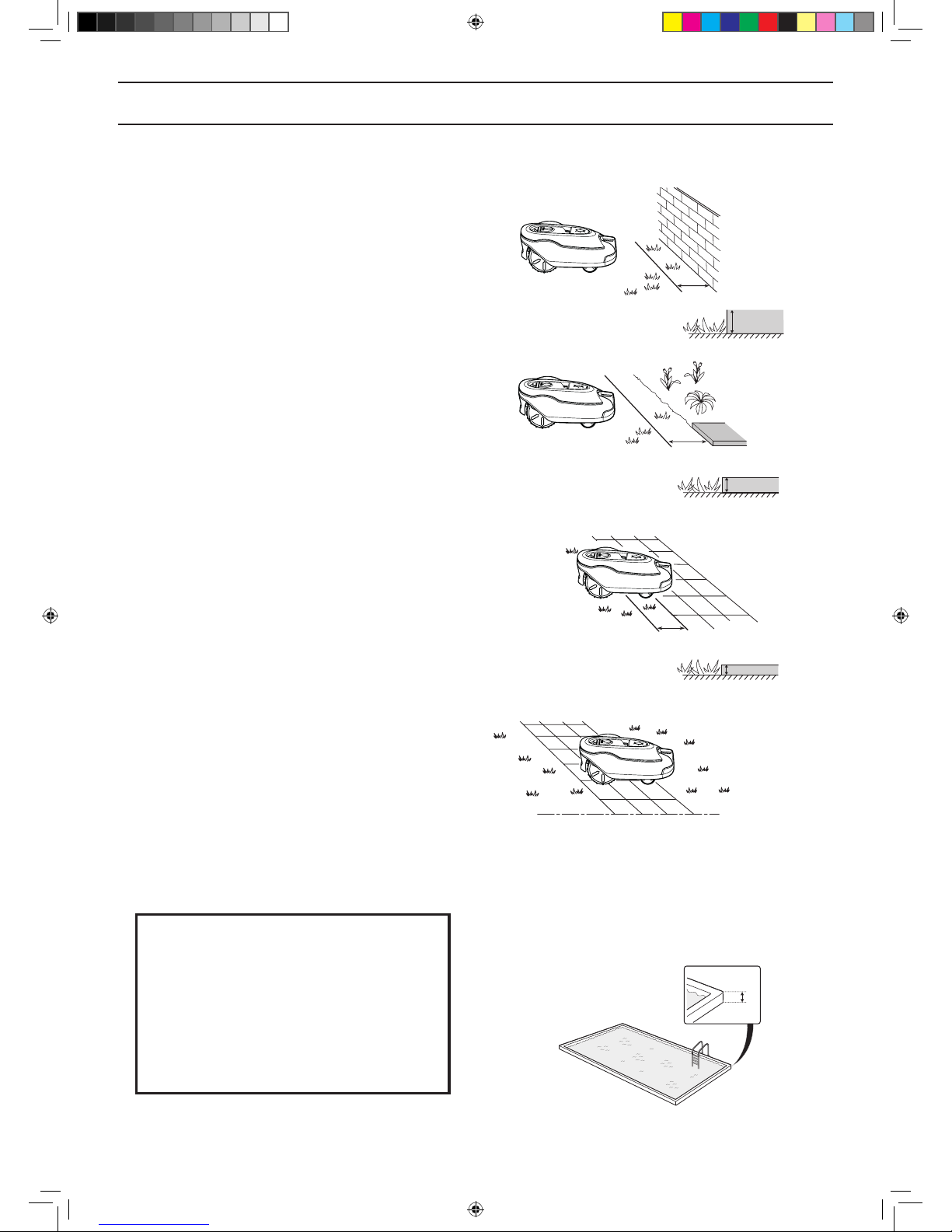
Working area boundaries
If a high obstacle (5 cm or more), for example a wall
or fence, borders the working area, the boundary wire
should be laid 35 cm from the obstacle. This will prevent
the robotic lawnmower from colliding with the obstacle
and reduce body wear.
About 20 cm of the lawn around the xed obstacle will not
be mown.
If the working area borders on a small ditch, for example
a ower bed or a small elevation, for example a low
kerbstone (1-5 cm), the boundary wire should be laid
30 cm inside the working area. This prevents the wheels
from driving into the ditch or up onto the kerbstone
which might be lead to excessive wear on the robotic
lawnmower, and especially the front wheels.
About 15 cm of the lawn along the ditch/kerbstone will not
be mown.
If the working area borders on a paving stone path or
similar that is level with the lawn (+/- 1 cm), it is possible
to allow the robotic lawnmower to run a little over the
path. The boundary wire should then be laid 10 cm from
the edge of the path.
All the grass along the side of the paving stone path will
be cut.
When the working area is divided by a paving stone
path that is level with the lawn, it is possible to allow the
robotic lawnmower to run over the path. It can be an
advantage to lay the boundary wire under the paving
stones. The boundary wire can also be laid in the joint
between the paving stones. Ensure that the tiles are in
level with the lawn to avoid excessive wear on the robotic
lawnmower.
Note: The robotic lawnmower must never run over
gravel, mulch or similar material which can damage the
blades.
IMPORTANT INFORMATION
If the working area is adjacent to water
bodies, slopes, precipices or a public
road, the boundary wire must be supplemented with an edging or the like. It must
then be at least 15 cm in height. This will
prevent the robotic lawnmower from ending up outside the working area under any
circumstance.
Min.
15cm
3018-046
35 cm
> 5 cm
3018-205
1-5 cm
30 cm
3018-206
10 cm
max 1 cm
3018-208
3018-207
1157808,Gardena_R100Li-R130Li,GB_151217.indd 22 2016-01-12 09:16:12
English - 23
INSTALLATION
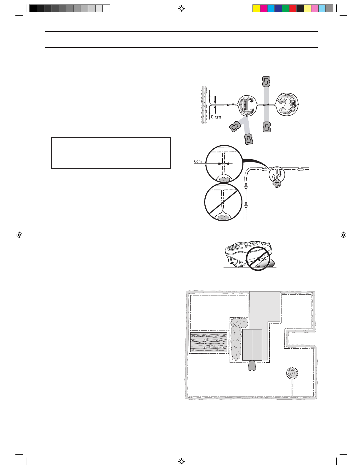
Boundaries within the working area
Use the boundary wire to isolate areas inside the working
area by creating islands around obstacles which cannot
withstand a collision, for example owerbeds, bushes and
fountains. Lay the wire up to and around the area to be
isolated, and then return it back along the same route.
If pegs are used, the wire should be laid under the same
pegs on the return route. When the boundary wires to
and from the island are laid close together, the robotic
lawnmower can drive over the wire.
Obstacles that can withstand a collision, for example,
trees or bushes taller than 15 cm, do not need to be
isolated with the boundary wire. The robotic lawnmower
will turn around when it collides with this type of obstacle.
It is recommended to isolate all xed objects in and
around the working area. This results in the most gentle
and silent operation and prevent the robotic lawnmower
from getting stuck in the objects under any circumstances.
Obstacles that slope slightly, for example stones or large
trees with raised roots, must be isolated or removed.
Otherwise the robotic lawnmower can slide up onto this
kind of obstacle causing the blades to be damaged.
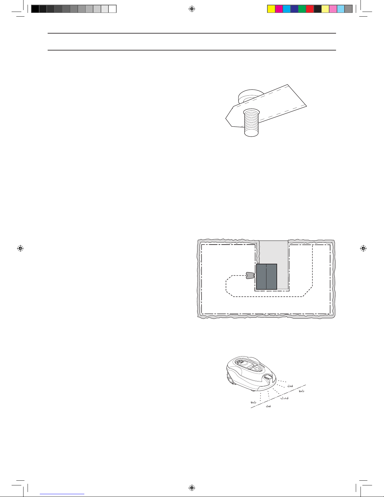
Secondary areas
If the working area consists of two areas which the
robotic lawnmower has difculty travelling between, it is
recommended to set up a secondary area. Instances of
this are 35% slopes or a passage that is narrower than
60 cm. Lay the boundary wire then around the secondary
area so that it forms an island outside of the main area.
The robotic lawnmower must be moved manually
between the main and secondary area when the lawn
in the secondary area has to be cut. The Secondary
area (A) operating mode must be used as the robotic
lawnmower cannot travel on its own from the secondary
area to the charging station. See 5.1 Operation selection
Start on page 40. In this mode, the robotic lawnmower
will never look for the charging station but will mow until
the battery runs out. When the battery is at, the robotic
lawnmower will stop and the Needs manual charging
message will appear in the display. Then place the robotic
lawnmower in the charging station to charge the battery.
If the main area has to be cut straight after charging, the
START button must be pressed and the Main area (B)
selected before closing the hatch.
IMPORTANT INFORMATION
The boundary wire may not be crossed on
its way to and from an island.
3023-005
3012-686
3018-209
A
B
3023-006
1157808,Gardena_R100Li-R130Li,GB_151217.indd 23 2016-01-12 09:16:14
English - 24
INSTALLATION
Passages when mowing
Long and narrow passages and areas narrower than
1.5 to 2 metres should be avoided. When the robotic
lawnmower mows, there is a risk that it travels around in
the passage or area for a long period of time. The lawn
will then look attened.
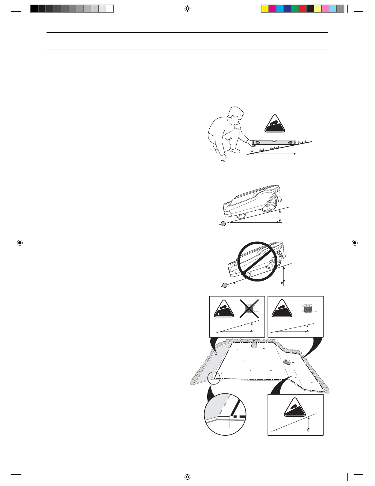
Slopes
The robotic lawnmower can also operate on sloping
working areas. The maximum gradient is dened as
percentage units (%). The slope as a percentage is
calculated as the difference in elevation in centimetres
for every metre. If for instance the difference in elevation
is 10 cm, the slope gradient is 10%. See the illustration.
The boundary wire can be laid across a slope that slants
less than 15%.
The boundary wire should not be laid across a slope
that is steeper than 15%. There is a risk that the robotic
lawnmower will nd it difcult to turn there. The robotic
lawnmower will then stop and the Outside working area
fault message is displayed. The risk is at its greatest in
damp weather conditions, as the wheels can slip on the
wet grass.
However, the boundary wire can be laid across a slope
steeper than 15% if there is an obstacle that the robotic
lawnmower is allowed to collide with, for example, a
fence or a dense hedge.
Inside the working area the robotic lawnmower can mow
areas which slope up to 35%. Areas that slope more must
be isolated with the boundary wire.
When a part of the working area’s outer edge slopes
more than 15%, the boundary wire must be laid about 20
cm in on the at ground before the beginning of the slope.
0-15%
0-15 cm
100 cm
3018-210
15-%
15- cm
100 cm
3018-211
100 cm
10 cm
10%
3012-1346
15%
0-15%
0-35%
15- cm
0-15 cm
0-35 cm
100 cm 100 cm
100 cm
20 cm
3012-1347
1157808,Gardena_R100Li-R130Li,GB_151217.indd 24 2016-01-12 09:16:17
English - 25
INSTALLATION
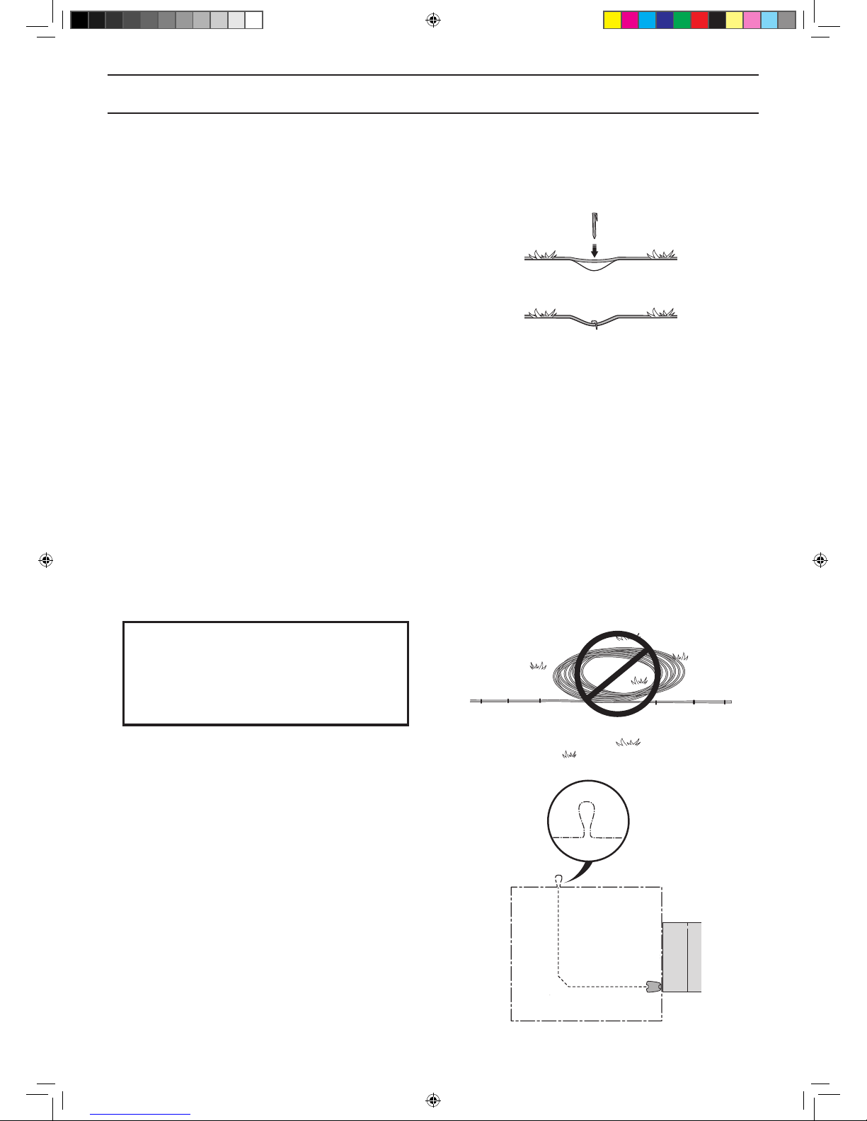
Laying the boundary wire
If you intend to peg down the boundary wire:
• Cut the grass very low with a standard lawnmower
or a trimmer where the wire is to be laid. It will then
be easier to lay the wire close to the ground and
the risk of the robotic lawnmower cutting the wire
or damaging the insulation of the wire is reduced.
• Make sure to lay the boundary wire close to the
ground and secure the pegs close together. The
cable must lie close to the ground so as not to be cut
before the grass roots have grown over it.
• Use a hammer to knock the pegs into the ground.
Exercise care when knocking in the pegs and make
sure the wire is not under strain. Avoid sharp bends in
the wire.
If the boundary wire is to be buried:
• Make sure to lay the boundary wire at least 1 cm and
a maximum of 20 cm in the ground. The wire can be
buried for instance using an edge cutter or a straight
spade.
Use the supplied measurement gauge as a guide when
you lay out the boundary wire. This helps you to easily set
the correct distance between the boundary wire and the
boundary/obstacle. The measurement gauge is broken
loose from the box.
IMPORTANT INFORMATION
Extra wire must not be placed in coils
outside the boundary wire. This can
disrupt the robotic lawnmower.
Eyelet for connecting the guide wire
To facilitate the connection of the guide wire to the
boundary wire, it is recommended to create an eyelet with
about 20 cm of extra boundary wire at the point where the
guide wire will later be connected. It is a good idea to plan
where the guide wire will be placed before laying out the
boundary wire. See 3.6 Installation of the guide wire on
page 28.
3018-085
3012-281
3023-007
1157808,Gardena_R100Li-R130Li,GB_151217.indd 25 2016-01-12 09:16:18
 Loading...