


DX2517
Galaxy DX Radios DX2517
y
Documentation Project
CBTricks.com
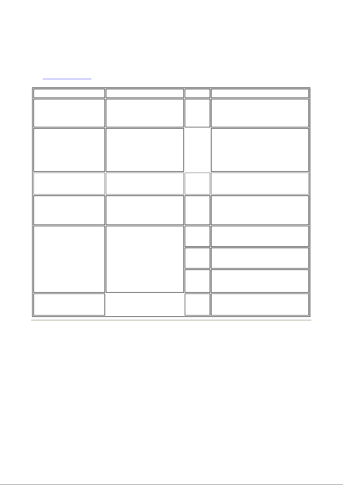
PLL Alignment
See Alignment Location
Seite 1 von 1Galaxy Radios DX2517 Service Manual
SETTINGS CONNECTION
REGULATOR VOLTAGE:
RX Mode, AM,
Band D, Ch. 1
10.240 MHz PLL
REFERENCE:
RX Mode, AM,
Band D, Ch. 1
Remove TP7-TP9
Jumper PCB.
VCO OUTPUT:
RX Mode, AM,
Band D, CH. 1
VCO VOLTAGE:
RX Mode, AM,
Band D, CH. 1
PLL MIXER
OSCILLATOR:
RX Mode, AM,
Band D, CH. 1
Set Fine and coarse
clarifier control to
oclock position.
Set clarifier switch
to RX/TX
12
Connect Voltmeter positive
lead to power switch.
Connect Voltmeter negative
lead to PCB ground.
Connect Frequency counter
to IC3 Pin 4.
Connect scope to TP3
Connect DC voltmeter to
TP2
Connect Frequency Counter
to TP3.
ADJUST
VR601 Adjust for 14.3 VDC
ADJUST FOR
Check for 10.2400MHz 200 Hz. If
tolerance is beyond this, replace X1
(10.240MHz).
L15
L14 Adjust for 2.75 VDC 0.1 Vdc.
L17 AM: Adjust for
L18 USB: Adjust for
L19 LSB: Adjust for
Adjust for max. RF
Check Band A, CH. 1 for approx.
2.0V. and Band H.
CH. 40 for approx. 6.0V.
16.2700MHz 20 Hz.
16.2725MHz 20 Hz.
16.2675MHz 20 Hz.
FREQUENCY COUNTER:
Set mode to AM RX
Band D, CH.1
Disclaimer: Although the greatest care has been taken while compiling these documents,
we cannot guarantee that the instructions will work on ever
VC1 on
Counter
PCB
Copyright © 1998,1999,2000, 2001 CBTricks.com
Adjust VC1 on counter PCB for
correct reading on display.
radio presented.
13.11.2006http://www.cbtricks.com/radios/galaxy/dx2517/dx2517_pll_adj.htm
 Loading...