


Printed In Malaysia AT2547010A PD0009028
DX 2547
POWER
TALKBACK
OFF 
PHONES
MIC
S |
|
5 |
7 |
|
9 |
+20 |
+40 |
dB |
|
1 |
3 |
|
40% |
|
|
80% |
+60 |
||
|
|
|
60% |
100% |
|||||
|
20% |
|
|
|
|
|
|
||
MOD |
|
3 |
6 |
|
9 |
12 |
15 |
|
|
|
|
2 |
3 |
|
MAX |
|
|||
PWR |
0 |
|
|
|
|
|
|||
SWR |
|
1.5 |
|
|
|
|
|
|
|
1 |
|
|
|
|
|
|
|
||
AM / SSB Base Station CB Radio
DX 2547
RF POWER |
SWR MOD PWR |
|
|
|
R. B. |
MIC RF |
DIM TONE |
PA |
OFF 
|
|
|
|
|
NORMAL |
|
|
|
|
|
|
9 |
19 |
|
GNF R.B. |
PA |
USB |
AM LSB |
|
|
|
CHANNEL |
|
ANL |
NB |
|
|
RX / TX |
SWR ALERT |
|
|
|
SQUELCH |
|
|
|
|
|
|
||
|
|
ANL |
NB |
|
|
|
|
|
GNF |
CLARIFIER |
|
|
|
|
USB |
AM |
LSB |
CLARIFIER |
VOLUME |
|
AM/ SSB Two Way
Citizen Band Base Station Transceiver
OWNER’S MANUAL

TABLE OF CONTENTS |
|
|
PAGE |
CHAPTER 1 |
|
Specifications . . . . . . . . . . . . . . . . . . . . . . . . . . . . . . . . . . . . . . . . . |
2 |
CHAPTER 2 |
|
Installation . . . . . . . . . . . . . . . . . . . . . . . . . . . . . . . . . . . . . . . . . . . |
3 |
Location . . . . . . . . . . . . . . . . . . . . . . . . . . . . . . . . . . . . . . . . . . . . |
3 |
Ignition Noise Interference . . . . . . . . . . . . . . . . . . . . . . . . . . . . . . |
3 |
Antenna . . . . . . . . . . . . . . . . . . . . . . . . . . . . . . . . . . . . . . . . . . . . . |
3 |
External Speaker . . . . . . . . . . . . . . . . . . . . . . . . . . . . . . . . . . . . . . |
5 |
Phone Jack . . . . . . . . . . . . . . . . . . . . . . . . . . . . . . . . . . . . . . . . . . |
5 |
Public Address . . . . . . . . . . . . . . . . . . . . . . . . . . . . . . . . . . . . . . . |
5 |
CHAPTER 3 |
|
Operation . . . . . . . . . . . . . . . . . . . . . . . . . . . . . . . . . . . . . . . . . . . . |
6 |
Control Function . . . . . . . . . . . . . . . . . . . . . . . . . . . . . . . . . . . . . . |
6 |
Front Panel . . . . . . . . . . . . . . . . . . . . . . . . . . . . . . . . . . . . . . . . . . |
6 |
Rear Panel . . . . . . . . . . . . . . . . . . . . . . . . . . . . . . . . . . . . . . . . . . . |
10 |
Frequency Chart . . . . . . . . . . . . . . . . . . . . . . . . . . . . . . . . . . . . . . |
11 |
Procedure to Receive And Transmit . . . . . . . . . . . . . . . . . . . . . . . |
12 |
Receiving SSB Signals . . . . . . . . . . . . . . . . . . . . . . . . . . . . . . . . . |
13 |
Alternate Microphone And Installation . . . . . . . . . . . . . . . . . . . . |
15 |
Maintenance and Adjustment . . . . . . . . . . . . . . . . . . . . . . . . . . . . |
18 |
A Few Rules That Should Be Obeyed . . . . . . . . . . . . . . . . . . . . . |
19 |
How Your CB can Serve You . . . . . . . . . . . . . . . . . . . . . . . . . . . . |
19 |
Use Channel 9 for Emergency Message Only . . . . . . . . . . . . . . . |
20 |
Warranty . . . . . . . . . . . . . . . . . . . . . . . . . . . . . . . . . . . . . . . . . . . . |
21 |
- 1 -
CHAPTER 1 SPECIFICATIONS
GENERAL
Channels |
40 |
Frequency Range |
26.965 ~ 27.405 MHz |
Emission |
AM/USB/LSB |
Frequency Control |
Phase-Lock-loop (PLL) Synthesizer |
Frequency Tolerance |
0.005% |
Frequency Stability |
0.003% |
Temperature Range |
-30°C to +50°C |
Antenna Impedance |
50 Ohms |
Antenna Connectors |
Standard SO-239 type |
Meter Function |
Meter#1 RF output Power / Antenna SWR |
|
Meter#2 Received signal strength / MOD % |
Input Voltage |
AC 120V, 60Hz |
TRANSMITTER
RF Power Output |
AM 4W ; USB/LSB 12W PEP |
Antenna Connector |
UHF Type, 50 Ohms |
AM Modulation |
Up to 100% |
Spurious Emission |
Better than -60 dB |
Unwanted Sideband |
Better than -60 dB |
RECEIVER
Sensitivity for 10 dB (S+N)/N |
AM : 0.5 uV, USB/LSB : 0.15 uV |
Adjacent Channel Rejection |
-60dB |
Image Rejection |
-50dB |
AGC Figure of Merit |
50 mV for 10dB Change in Audio Output |
Audio Power Output |
2.5W @ 10% Distortion |
Audio Response |
300 to 2500 Hz |
- 2 -
CHAPTER 2 INSTALLATION
LOCATION
Choose a location close to an AC power outlet and convenient for running the antenna lead-in cable. This transceiver is attached with the AC power cord set. Proceed as follows to complete all necessary connections to the transceiver.
1.Your transceiver has a standard antenna connector type, SO-239 located on the rear panel for easy connection to the standard PL-259 coax plugs. If the coax antenna cable must be made longer, use only enough coax cable to suit your needs with impedance of 50 ohms, frequency range from 26.965 to 27.405 MHz. This will insure proper impedance match and maximum power transfer from the transmitter to the antenna.
2.Use 120V AC power for the base station.
NOISE INTERFERENCE
There are several kinds of noise interference you may encounter in base station operation. Some of these noises come from fluorescent light, electrical appliance, lawnmower, nearby commercial broadcast etc. Commercial products are available to reduce interference from these sources. Consult your dealer or professional amateur radio supplier.
Even though the transceiver has ANL and NB controls, in some installation ignition interference may be high enough to make good communications impossible. The electrical noise may come from several sources. Many possibilities exist as variations between vehicles require different solutions to reduce the noise.
ANTENNA
For best transmission and reception, your transceiver should use an antenna especially designed for a frequency of 27 MHz. Antenna is to be purchased separately and it comes with the installation instructions. Numerous types of antennas are available. Some emphasize on ease of installation while others emphasize on performance. Often the difference in performance for these antennas is modest.
- 3 -
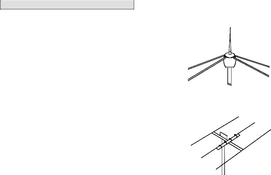
1.Vertical Ground Plane Antenna : Omni directional antennas provide optimum performance for contacting other fixed stations using vertical type antennas in addition to all mobile stations. For medium long range communications work.
Ground Plane
2.Directional Beam Antenna : Highly efficient and directional antenna generally intended for fixed-to-fixed long range communications.
Directional Beam Antenna
- 4 -

EXTERNAL SPEAKER
The external speaker jack (EXT. SP.) on the rear panel is used for remote receiver monitoring. The external speaker should have 8 ohms impedance and be able to handle at least 4 watts. When the external speaker is plugged in, the internal speaker is disconnected.
PHONE JACK
This PHONE jack accepts headphone of 4 to 32 ohms impedance. When a headphone is plugged into this jack, both internal and external speakers are silenced simultaneously.
PUBLIC ADDRESS
To use the transceiver as a public address system, connect an external 8 ohms speaker (4 watts minimum) to the PA. SP. jack located on the rear panel. Direct speaker away from the microphone to prevent acoustic feedback. Physical separation or isolation of the microphone and speaker is important when operating the PA at high output levels.
- 5 -
CHAPTER 3 OPERATION
CONTROL FUNCTIONS
FRONT PANEL
POWER
TALKBACK
OFF 
PHONES
MIC
S |
|
5 |
7 |
9 |
+20 |
|
|
dB |
||
3 |
|
40% |
|
80% |
|
+40 |
+60 |
|||
1 |
|
|
60% |
100% |
||||||
|
20% |
|
|
|
|
|
|
|||
MOD |
|
3 |
|
6 |
9 |
12 |
15 |
|
|
|
|
|
2 |
3 |
|
MAX |
|
||||
PWR |
0 |
|
|
|
|
|
|
|||
SWR |
|
1.5 |
|
|
|
|
|
|
|
|
1 |
|
|
|
|
|
|
|
|
||
AM / SSB Base Station CB Radio
|
DX 2547 |
RF POWER |
SWR MOD PWR |
R. B.
MIC RF |
DIM TONE |
PA |
|
OFF |
|
|
|
|
|
|
NORMAL |
|
|
|
|
|
|
9 |
19 |
|
GNF R.B. |
PA |
USB |
AM LSB |
|
|
|
CHANNEL |
|
ANL |
NB |
|
|
RX / TX |
SWR ALERT |
|
|
|
|
|
|
|
|
|
|
SQUELCH |
|
|
|
ANL |
NB |
|
|
|
|
|
GNF |
CLARIFIER |
|
|
|
|
USB |
AM |
LSB |
CLARIFIER |
VOLUME |
|
1.PHONE JACK : Used to connect headphones for listening.
2.MICROPHONE JACK : Used to connect microphone for voice source.
3.RF POWER CONTROL : This control allows the user to adjust RF power output.
4.RF GAIN CONTROL : This control is used to reduce the gain of the RF amplifier under strong signal conditions.
5.MIC GAIN CONTROL : Adjust the microphone gain in the transmit and PA modes. This controls the gain to the extent that full talk power is available several inches away from the microphone. In the Public Address (PA) mode, the control function as the volume control.
-6 -
 Loading...