


DX 94HP
10 Meter
Amateur Mobile Transceiver
With Built-in Frequency Counter &
StarLite Face Plate
OWNER’S MANUAL
|
TABLE OF CONTENTS |
|
PAGE |
CHAPTER 1 |
|
Specifications . . . . . . |
. . . . . . . . . . . . . . . . . . . . . . . . . . . . . . . . . . . . . . . . 2 |
CHAPTER 2 |
|
Installation . . . . . . . . . . . . . . . . . . . . . . . . . . . . . . . . . . . . . . . . . . . . . . . . |
3 |
Installing The Radio . . . . . . . . . . . . . . . . . . . . . . . . . . . . . . . . . . . . . . . . |
3 |
Ignition Noise Interference . . . . . . . . . . . . . . . . . . . . . . . . . . . . . . . . . . . |
4 |
Antenna . . . . . . . . . . . . . . . . . . . . . . . . . . . . . . . . . . . . . . . . . . . . . . . . . . |
4 |
External Speaker . . . . . . . . . . . . . . . . . . . . . . . . . . . . . . . . . . . . . . . . . . . |
4 |
Public Address . . . . . . . . . . . . . . . . . . . . . . . . . . . . . . . . . . . . . . . . . . . . |
4 |
CHAPTER 3 |
|
Operation . . . . . . . . . . . . . . . . . . . . . . . . . . . . . . . . . . . . . . . . . . . . . . . . . |
5 |
Front Panel . . . . . . . . . . . . . . . . . . . . . . . . . . . . . . . . . . . . . . . . . . . . . . . |
5 |
Rear Panel . . . . . . . . . . . . . . . . . . . . . . . . . . . . . . . . . . . . . . . . . . . . . . . . |
8 |
Procedure to Receive and Transmit . . . . . . . . . . . . . . . . . . . . . . . . . . . . |
9 |
Receiving SSB Signals . . . . . . . . . . . . . . . . . . . . . . . . . . . . . . . . . . . . . . |
10 |
Alternate Microphone and Installation . . . . . . . . . . . . . . . . . . . . . . . . . . |
12 |
1

|
CHAPTER 1 SPECIFICATIONS |
||
|
|
|
|
GENERAL |
|
|
|
Model |
DX 94HP |
|
|
Frequency Range |
28.315 ~ 28.755 MHz |
|
|
Emission |
AM/USB/LSB |
|
|
Frequency Control |
Phase-Lock-Loop (PLL) Synthesizer |
||
Frequency Stability |
0.001% |
|
|
Temperature Range |
-30°C to +50°C |
|
|
Antenna Impedance |
50 Ohms |
|
|
Antenna Connectors |
Standard SO-239 type |
|
|
Input Voltage |
13.8V DC |
|
|
Size |
7 3/4" (W) x 2 7/8" (H) x 10 1/4" (D) |
||
Weight |
6 lb. |
|
|
TRANSMITTER |
|
|
|
RF Power Output |
AM: 5W~40W |
|
|
|
|
USB/LSB: 100W PEP |
|
Transmit Current |
AM: 14 Amps |
SSB: 25 Amps |
|
Spurious Emission |
-50 dB |
|
|
Unwanted Sideband |
-50 dB |
|
|
Audio Distortion |
10% |
|
|
Frequency Response |
300 to 2500Hz |
|
|
Microphone |
Dynamic |
|
|
Clarifier Range |
Coarse: ± 6.0KHz, Fine: ± 1.0KHz |
||
RECEIVER |
|
|
|
Sensitivity for 10 dB (S+N)/N |
AM: < 0.5 μV; USB/LSB: < 0.25 μV |
||
Squelch Sensitivity |
< 0.5 uV |
|
|
Selectivity |
-55 dB |
|
|
Image Rejection |
-50 dB |
|
|
AGC Figure of Merit |
100 mV for 10dB Change in Audio Output |
||
Audio Power Output |
2.5W @ 10% Distortion |
||
Audio Response |
300 to 2500 Hz |
|
|
(SPECIFICATIONS SUBJECT TO CHANGE WITHOUT NOTICE)
2
CHAPTER 2 INSTALLATION
INSTALLING THE RADIO
Choose a convenient location for operation that does not interfere with driver or passenger. This radio is supplied with a universal mounting bracket. When mounting the bracket and radio to your car, make sure it is mechanically strong. Also, provide a good electrical grounding connection to the chassis of vehicle. Proceed as follows to install the radio.
1.Locate a convenient area in your vehicle for the installation of the radio. Hold the mounting bracket with the radio in the location where the radio is to be installed. Make sure nothing will interfere with either the radio or the mounting bolts. Mark and then drill holes for the mounting bracket.
2.Most radio antennas come equipped with a PL-259 plug. Connect this plug to the ANT. Jack in the rear of the radio.
3.Extending from the rear of the radio is a fused red and black wire for the DC connections to the vehicle’s electrical system. For best performance, it is strongly recommended that red lead be connected directly to the positive terminal on the vehicle’s battery and the black lead be connected directly to the negative terminal on the battery. (Note, not connecting both leads direct to the battery may cause performance problems) This radio is designed for vehicles with negative ground systems.
Connections should be made using appropriate “crimp on” lugs of a size large enough to make good contact with the bolt used to fasten to the battery and the chassis ground. It is a good safety idea to install a second 30 amp fuse that would provide protection in case the red wire was to “fray” or get pinched and short to the body of the vehicle, somewhere between the battery and the radio.
High power radios such as this one require large DC current flow when in the TX mode. Poor power connections cause supply voltage drops that can substantially decrease the performance of your radio. A good DC connection is probably one of the most important things for getting the best transmitter performance and in some cases, least receiver noise.
4.Mount the microphone bracket near the radio in an easily accessible spot using the two screws provided.
3
IGNITION NOISE INTERFERENCE
With weak signals, you may experience interference of the signal by background noise. This radio has NB and ANL circuits that will help reduce background noise from sources such as your ignition system. However, background electrical noise may come from several sources and all noise may not be eliminated. With extremely weak signals, you can operate this radio with the engine turned off, which should improve reception. If the ignition noise level is too high to allow proper operation under most conditions, you should have your installation of the radio checked by a qualified technician.
ANTENNA
This radio has a jack in the rear for a standard PL-259 antenna plug. If you are looking for the most range for your transmission, use a vertically polarized, quarterwave length antenna. If antenna height is a problem, you may use a shorter, loaded-type whip antenna although you can expect some loss of transmission range.
To improve performance, your antenna should be matched to your radio. Your antenna can be adjusted so that it matches your radio.
EXTERNAL SPEAKER
The external speaker jack (EXT SP.) on the rear panel is used for remote receiver monitoring. The external speaker should have 8 ohms impedance and be able to handle at least 4 watts. When the external speaker is plugged in, the internal speaker is disconnected.
PUBLIC ADDRESS
To use the Public Address (PA) function, first connect an external speaker to the PA. SP. Jack on the rear of the radio. See the above specifications for a proper external speaker. Keep the speaker away from the microphone to avoid acoustic feedback.
4
CHAPTER 3 OPERATION
CONTROL FUNCTIONS
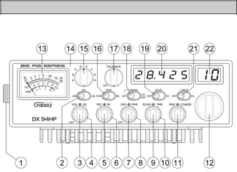
FRONT PANEL
1.MICROPHONE JACK: Used to connect microphone.
2.MODE SWITCH: This control allows you to select one of the following operating modes: AM/USB/LSB.
3.ON/OFF VOLUME CONTROL: This knob controls the volume and power to the radio. To turn radio on, rotate the knob clockwise. Turning the knob further will increase the volume of the receiver.
4.SQUELCH CONTROL: This knob is used to eliminate background noise being heard through the receiver, which can be disturbing when no transmissions are being heard through the receiver. To use this feature, turn the knob fully counterclockwise and then turn clockwise slowly until the background noise is just eliminated. Further clockwise rotation will increase the threshold level that a signal must overcome in order to be heard. Only strong signals will be heard at a maximum clockwise setting.
5.MIC GAIN CONTROL: Adjusts the microphone gain in transmit and PA modes. This controls the gain to the extent that full talk power is available several inches
5
away from the microphone. In the Public Address (PA) mode, the control functions as the volume control.
6.RF GAIN CONTROL: Adjust this knob for desired level of incoming signal.
7.DIM CONTROL: This knob controls the level of brightness for the meter lamp, faceplate, frequency display and channel display. Turn clockwise to activate backlight circuit.
8.RF POWER CONTROL: This control allows the user to adjust RF power output.
9.ECHO CONTROL: This control is used to adjust echo effect.
10.TIME CONTROL: This control is used to adjust intervals of echo.
11.FINE/COARSE CONTROL: Allows variation of the radio operating frequencies above and below the channel frequency. Although this control is intended primarily to tune in SSB signals, it may be used to optimize AM signals.
12.CHANNEL SELECTOR: This control is used to select the desired transmit and receive channel.
13.FRONT PANEL METER: The front panel meter allows the user to monitor incoming signal strength, RF output power and SWR level.
14.ILLUMINATED FACE PLATE: All faceplate lettering will fully illuminate to allow the user easy viewing at night. This unique, solid state, backlight is designed to maximize night vision while minimizing eye fatigue. Therefore, it is ideal for both day or night.
15.BAND SELECTOR: This switch is used to select the band.
16.PWR/SWR/RB SWITCH: When in the RB position, the radio transmits an audio tone at the end of your transmission to indicates that transmission has ended. As a courtesy to others, use the Roger Beep only when necessary. When the switch is in the “SWR” position, the meter indicates the Standing Wave Ratio (SWR) of your antenna. There are no adjustments because the SWR circuit in this radio calibrates itself automatically (accurate at maximum power output). When this switch is in “PWR” position, the meter indicates your power output.
17.TALKBACK CONTROL: This feature is used to monitor your own voice. For example, you could use this feature to compare different microphones. This knob controls the volume of the Talkback level. The Talkback circuit is off when the MIC GAIN knob is depressed.
6
18.OFF/ NB/ANL /FD.OFF SWITCH: In the NB/ANL position, the RF Noise Blanker and the automatic Noise Limiter in the audio circuits are also activated. The Noise Blanker is very effective in eliminating repetitive impulse noise such as ignition interference. When the switch is in the F.D.OFF position, the frequency Display is OFF.
19.OFF/ECHO/VC SWITCH: With the switch in VC position you can adjust the tone and pitch of your voice. With the switch in ECHO you can add echo and reverb to your voice. In the OFF position your voice will sound natural.
20.FREQUENCY COUNTER: This display indicates the frequency of the selected channel.
21.OFF/+10K/PA SWITCH: When the switch is in the +10KHz position, the frequency is shifted up 10KHz. In the PA position, the radio acts as public address amplifier. Your voice will come out of the speaker that is plugged into the PA. SP. jack on the rear panel. The radio does not operate when you are in the PA mode.
22.CHANNEL DISPLAY: The channel display indicates the current selected channel.
7
 Loading...