

Page 1
Pub. 42004-724L2iQG
GAI-TRONICS® CORPORATION
A HUBBELL COMPANY
ICS Class I, Div. 2 W eatherproof Page/Party® Station Quic k Installa tion Guide
Important S afety Instructions
This equipmen t is suitable for use in Cla ss I, Division 2, Groups A, B, C and D, Class II Division 2, Groups F, and G, Class III OR non-hazardous locations only.
Combinations of equipment in your system are subject to investi gation by the local Authority Havin g Jurisdiction at the time of installa tion.
Read, follow, and retain instructions – All safety and operating instructions should be read and followed before operating the unit. Retain in str u ctions for future
reference.
Heed warnings – Adh ere to all warnings on the un it and in the operating instructions.
Attachments – Attachments not recommended by the product manufacturer should not be used, as they may cause hazards. Maximum system cable length is not to
exceed two miles.
Servicing – Do not at tempt to service this uni t by yourself. Opening or removing covers may expose you to dangerous voltage or other h azards. Refer all servicing to
qualified service personnel.
This permanently connected apparatus m ust have a UL Listed 15-amp circuit breaker incorporated in the electr ical installation of the building.
WARNING – EXPLOSION HAZARD – Do not disconnect equipment unless power has been removed or the area is known to be non-hazardous. Averttissement –
Risque d’explosion – avant de déconnector l’equipment, couper le courant ou s’assurer que l’emplacement est désigné non dangereux.
USA and Canada Consult the National Electrical Code (NFPA 70), Canadian Standards Association (CSA 22.1), and local codes for specific requirements regarding
your installation. Class 2 circuit wiring must be performed in accordance with NEC 725.55.
WARNING
In 24 V dc systems, m ost chargers have an unloaded output of 35 to 45 volts that can quickly damage the equipment designed for nominal 24 volts. The maximum
battery voltage should never exceed the maximum specified input voltage.
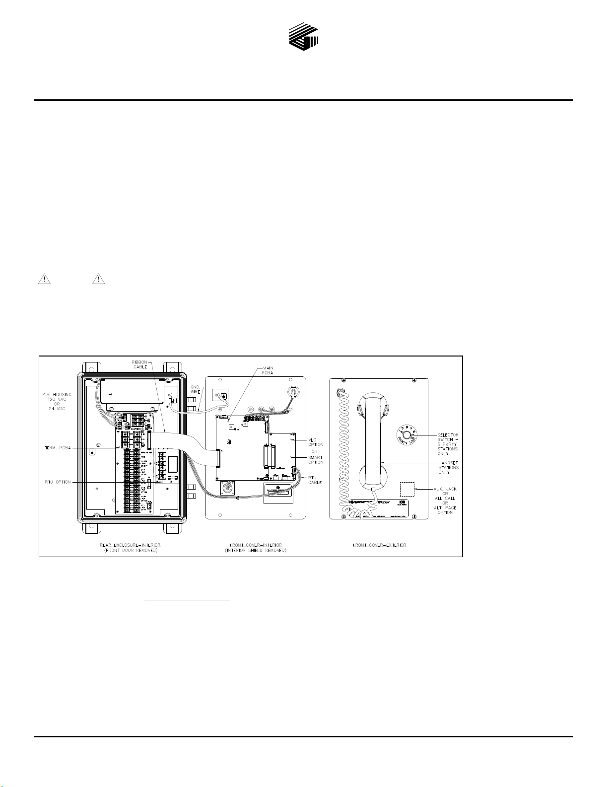
General Inf ormation and Available Options
This guide covers the installati o n of the ICS Weatherproof Page/Party
In 24 V dc systems: Under NO condition should this equipment be operated from a battery charger without the batteries connected.
®
Station. Figure 1 shows configurations wit h the following
options:
Universal ac or 24 V
dc power
Single or multi-
party
system, or amplifier
only
All Call
SmartSeries
Alternate page
destination
Emergenc y party
line (EPL)
Auxiliary jack
VLC
Figure 1. ICS Weatherproof Station with available options (AC Version shown)
RTU
All ICS Stations are wired in parallel. Good system layout design minimizes the cable required. Refer to Pub. 42004-724L2 at the
“Manuals & Specs” link at www.gai-tronics.com
for detailed explanations of the available configuration options and adjustments,
system design information, and warranty.
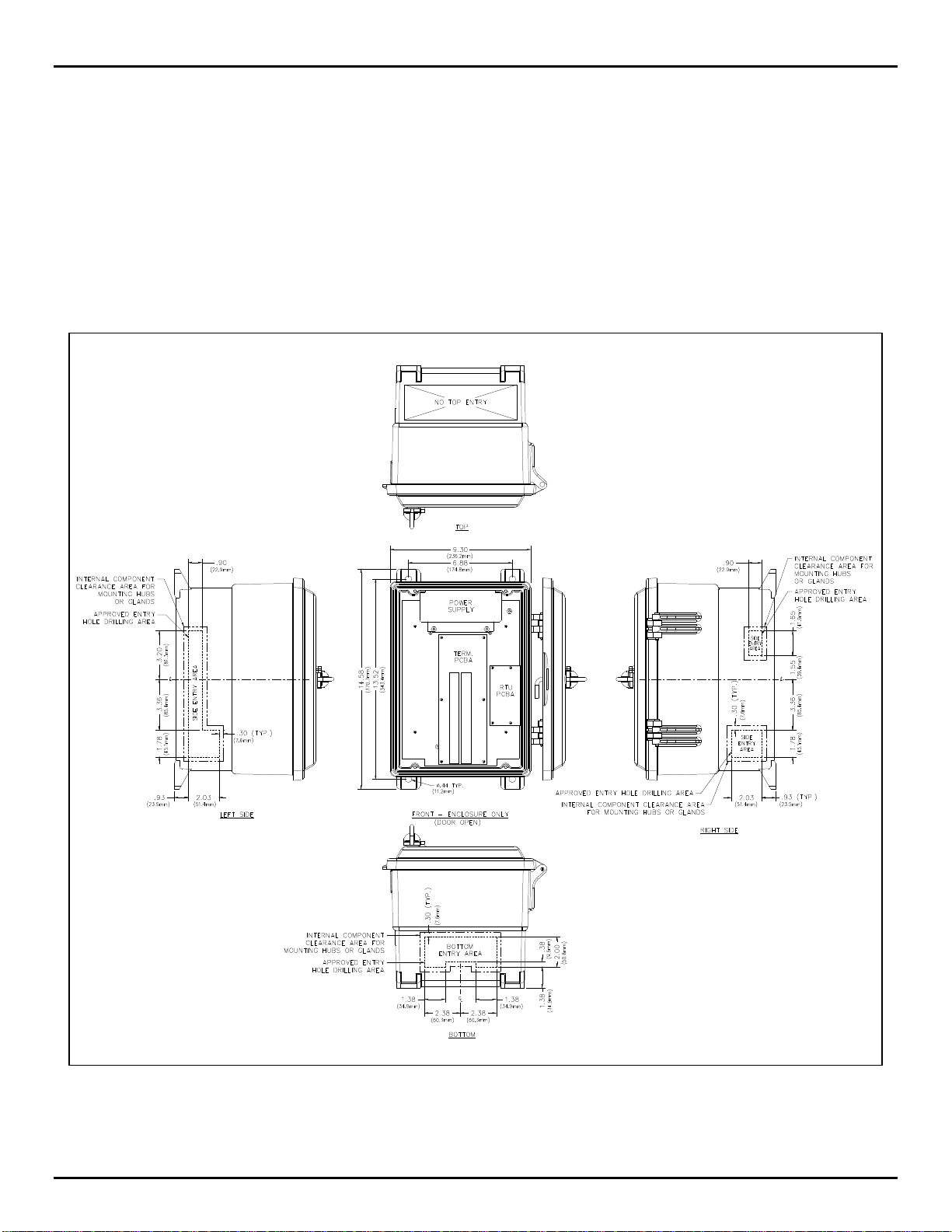
Mounting and Wiring
Mount the enclosure using the four 0.437-inch (11 mm) diameter holes located on the mounting flanges with 3/8-inch (M8) hardware.
Remove front panel and drill or punch wire entry openings in the rear enclosure. See Figure 2 for suggested locations. There must be
a minimum of ½ inch (12.7 mm) of material between wire entry holes. The recommended entry is via the enclosure bottom to prevent
moisture from dripping onto the terminals. Top entry is not permitted, as the power supply is located at the top of the enclosure.
Basic wiring connections are shown on Figure 3. Use GAI-Tronics 60029 series multi-party cable or 60038 series single party cable
terminated with #6 spade lugs. Torque the terminal block screws to 8–10 in-lbs (0.90–1.13 n-m) when attaching the spade lugs.
GAI-Tronics Corporation 400 E. Wyomissing Ave. Mohnton, PA 19540 USA
610-777-1374 800-492-1212 Fax: 610-796-5954
V
ISIT WWW.GAI-TRONICS.COM FOR PRODUCT LITERATURE AND MANUALS
Page 2
Pub. 42004-724L2iQG
ICS Class I, Div. 2 Weatherproof Page/Party
®
Station Quick Installation Guide Page 2 of 3
Available A djustments
Most optional equipment is preconfigured to a default standard at the factor y. The following is a partial list of the available
adjustments and settings that may be nee ded:
Main PCBA VLC Option SmartSeries Option
Speaker Volume Speaker Volume FSK Transmit Level
Receiver Volume VLC Override Address
T ransmit Level Test Tone
Mutual Muting Page Control
Remote Signaling Speaker Impedance
Termination PCBA
Figure 2. Suggested wire entry locations
f:\standard ioms - current release\42004-xxxxqg quick guides\42004-724l2iqg.doc
11/14
Page 3

ICS Class I, Div. 2 Weatherproof Page/Party
®
Station Quick Installation Guide Page 3 of 3
Pub. 42004-724L2iQG
Figure 3. Typical installation wiring configuration
OTE: Station input power can be through system cable or through a separate power source cable.
N
See Pub. 42004-724L2 for the possible beacon, RTU activation, and speaker impedance configurations.
Front Cov er Reattachment
Connect any cable harnesses that were disconnected during mounting. Place the front cover inside the rear enclosure, being careful
not to pinch any cables. Attach the front cover with the four screws and washers provided. Torque the screws to 10–12 in-lbs
(1.13–1.36 n-m).
NRTL Listed for USA and Canada ......................................................................................... Class I, Groups A, B, C, and D, Division 2;
Class II, Groups F and G, Division 2;
Class III, Division 2 Hazardous Locations
Temperature code, T4A – USA
T3C – Canada
f:\standard ioms - current release\42004-xxxxqg quick guides\42004-724l2iqg.doc
11/14
Page 4

Warranty
Equipment. GAI-Tronics warrants for a period of one (1) year from the date of shipment, that any
GAI-Tronics equipment supplied hereunder shall be free of defects in material and workmanship, shall
comply with the then-current product specifications and product literature, and if applicable, shall be fit
for the purpose specified in the agreed-upon quotation or proposal document. If (a) Seller’s goods prove
to be defective in workmanship and/or material under normal and proper usage, or unfit for the purpose
specified and agreed upon, and (b) Buyer’s claim is made within the warranty period set forth above,
Buyer may return such goods to GAI-Tronics’ nearest depot repair facility, freight prepaid, at which time
they will be repaired or replaced, at Seller’s option, without charge to Buyer. Repair or replacement shall
be Buyer’s sole and exclusive remedy. The warranty period on any repaired or replacement equipment
shall be the greater of the ninety (90) day repair warranty or one (1) year from the date the original
equipment was shipped. In no event shall GAI-Tronics warranty obligations with respect to equipment
exceed 100% of the total cost of the equipment supplied hereunder. Buyer may also be entitled to the
manufacturer’s warranty on any third-party goods supplied by GAI-Tronics hereunder. The applicability
of any such third-party warranty will be determined by GAI-Tronics.
Services. Any services GAI-Tronics provides hereunder, whether directly or through subcontractors,
shall be performed in accordance with the standard of care with which such services are normally
provided in the industry. If the services fail to meet the applicable industry standard, GAI-Tronics will
re-perform such services at no cost to buyer to correct said deficiency to Company's satisfaction provided
any and all issues are identified prior to the demobilization of the Contractor’s personnel from the work
site. Re-performance of services shall be Buyer’s sole and exclusive remedy, and in no event shall GAITronics warranty obligations with respect to services exceed 100% of the total cost of the services
provided hereunder.
Warranty Periods. Every claim by Buyer alleging a defect in the goods and/or services provided
hereunder shall be deemed waived unless such claim is made in writing within the applicable warranty
periods as set forth above. Provided, however, that if the defect complained of is latent and not
discoverable within the above warranty periods, every claim arising on account of such latent defect shall
be deemed waived unless it is made in writing within a reasonable time after such latent defect is or
should have been discovered by Buyer.
Limitations / Exclusions. The warranties herein shall not apply to, and GAI-Tronics shall not be
responsible for, any damage to the goods or failure of the services supplied hereunder, to the extent
caused by Buyer’s neglect, failure to follow operational and maintenance procedures provided with the
equipment, or the use of technicians not specifically authorized by GAI-Tronics to maintain or service the
equipment. THE WARRANTIES AND REMEDIES CONTAINED HEREIN ARE IN LIEU OF AND
EXCLUDE ALL OTHER WARRANTIES AND REMEDIES, WHETHER EXPRESS OR IMPLIED BY
OPERATION OF LAW OR OTHERWISE, INCLUDING ANY WARRANTIES OF
MERCHANTABILITY OR FITNESS FOR A PARTICULAR PURPOSE.
Return Policy
If the equipment requires service, contact your Regional Service Center for a return authorization number
(RA#). Equipment should be shipped prepaid to GAI-Tronics with a return authorization number and a
purchase order number. If the equipment is under warranty, repairs or a replacement will be made in
accordance with the warranty policy set forth above. Please include a written explanation of all defects to
assist our technicians in their troubleshooting efforts.
Call 800-492-1212 (inside the USA) or 610-777-1374 (outside the USA) for help identifying the
Regional Service Center closest to you.
(Rev. 10/06)
 Loading...