

Page 1
Pub. 42004-307G
GAI-TRONICS® CORPORATION
A HUBBELL COMPANY
Model GC-AC1, GC-DC1, and GC-AC2
EZ Page Industrial Intercoms
Confidential ity Notice
This manual is provided solely as an operational, installation, and maintenance guide and contains
sensitive business and technical information that is confidential and proprietary to GAI-Tronics.
GAI-Tronics retains all intellectual property and other rights in or to the information contained herein,
and such information may only be used in connection with the operation of your GAI-Tronics product or
system. This manual may not be disclosed in any form, in whole or in part, directly or indirectly, to any
third party.
General Information
Product Overview
GAI-Tronics’ EZ Page Intercoms are designed
for two-way communication in non-hazardous,
industrial applications. Each model is field
configurable for one of two types of systems:
either Listen/Talk or Master/Slave. All units are
factory-configured for the Listen/Talk system.
Listen/Talk System
In a Listen/Talk system, the press-to-talk switch
must be held down as long as the operator talks.
Releasing the switch deactivates the microphone
and returns the unit to the listen mode.
Master/Slave System
In a Master/Slave system the Master unit controls
the talk/listen operation of the Slave unit. The
Slave unit is normally in the talk mode, providing
hands-free communication to the operator. The
Master/Slave system is ideal for typical gate
station applications. An internal switch is used to
designate a unit as a master or as a slave.
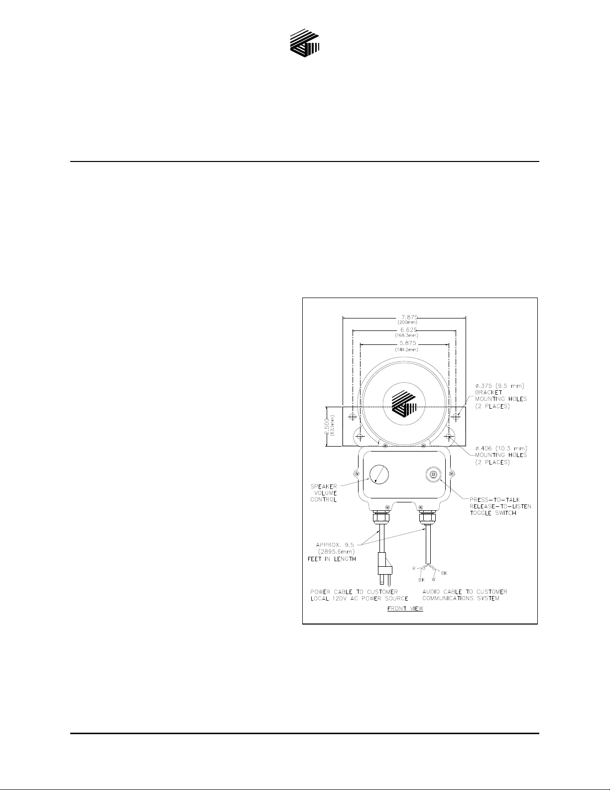
Figure 1. Intercom Outline Diagram
Balanced and Unbalanced Sys tems
The EZ Page system is a balanced system; however, it can be adapted for use in an unbalanced system. If
interfacing this equipment with other similar products on the market, determine if your system is balanced
or unbalanced.
(shown with optional mounting bracket installed)
GAI-Tronics Corporation 400 E. Wyomissing Ave. Mohnton, PA 19540 USA
610-777-1374 800-492-1212 Fax: 610-796-5954
V
ISIT WWW.GAI-TRONICS.COM FOR PRODUCT LITERATURE AND MANUALS
Page 2
Pub. 42004-307G
PAGE INDUSTRIAL INTERCOMS Page 2 of 16
EZ
The setting of an internal jumper and the external wiring interconnection scheme are different in a
balanced system and an unbalanced system. Refer to the appropriate installation instructions provided in
this manual.
System Requirements
Each unit requires local power within approximately 9.5 feet of unit for interconnection of unit’s
audio/control cable to system cable.
OTE: If applicable local electrical codes permit, the use of a combined UL-approved junction box for
N
termination of the unit’s local power connection
and audio/control to system cable could be
helpful.
Models
Input
Voltage
Interconnection
(Customer-supplied)
Cable Distance Limitations
OTE: Calculations are based on the use of No.
N
18 AWG twisted pair wire.
Audio Pair
Maximum distance from the line balance is
GC-AC1 120 V ac NEMA 5-15R style receptacle
GC-DC1 12-16 V dc Small junction box for Class 2
wiring
GC-AC2 230 V ac Small UL-approved junction
box or plug rated for this
voltage
approximately 1 mile (1.6 km). Maximum
distance between the two end units is approximately 2 miles (3.2 km).
External Control Pair
Maximum distance between the two end units is approximately 2 miles (3.2 km).
System Cable
Recommend use of twisted, two pair cable (No. 18 AWG) between stations for maximum system
hum/noise immunity. Extreme hum/noise areas may require shielded twisted, two pair cable.
Installation
Since a good installation is important in obtaining the best possible performance of the communications
system, determine the operating mode of each unit and carefully plan the overall installation before actual
work is started. Read the entire procedure and the many suggestions offered to help you plan your
installation.
DANGER
Do not install in a hazardous area. Use in safe, non-classified, non-hazardous
areas only.
WARNING
Please adhere to all the following safety and operating instructions on the
unit and in the installation manual:
Ensure that the installation is in accordance with all local applicable electrical codes.
Disconnect power to the unit before opening or servicing to avoid possible damage to equipment or
personal injury.
Avoid running system cable near high voltage/high electromagnetic sources.
Avoid servicing the unit during electrical storms.
Do not touch non-insulated wires.
f:\standard ioms - current release\42004 instr. man uals\42004-307g.doc
03/15
Page 3
Pub. 42004-307G
PAGE INDUSTRIAL INTERCOMS Page 3 of 16
EZ
Internal Settings
The following procedure describes how to change the internal settings. If the intercom will be used as a
Listen/Talk unit or as a Master unit in a balanced line system, then no changes to the internal PCBA’s
jumper or switch settings are required.
WARNING
Disconnect power to unit before opening to avoid possible damage to equipment or personal injury.
1. Disconnect power to the unit.
2. Loosen and remove the six screws securing the front cover.
3. Lift out the front panel assembly and tilt to the left. Use caution to ensure that no unnecessary strain
is placed on the attached wiring harnesses.
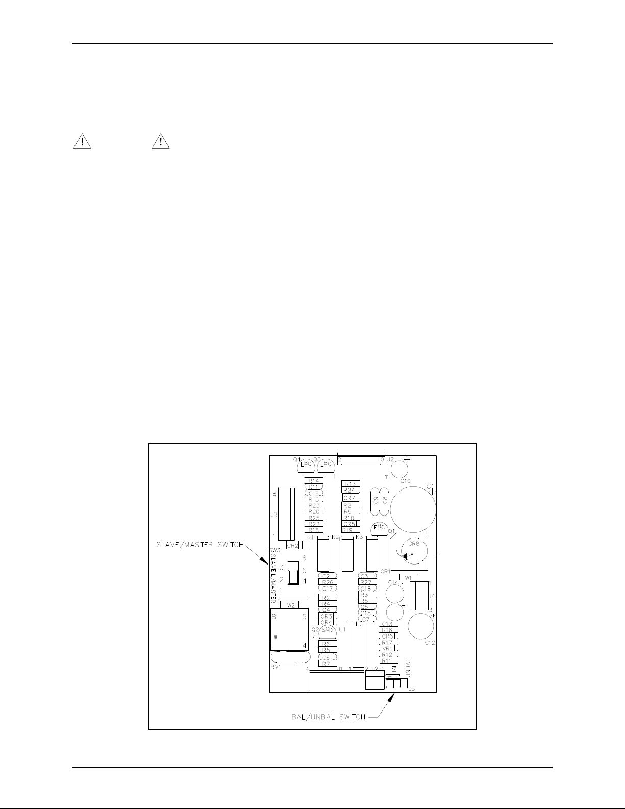
4. If configuring the unit as a slave, slide the PCBA’s mode switch (SW3) to the S
LAVE position. See
Figure 2.
5. If operating in an unbalanced cable system, reposition the PCBA’s jumper P5/J5 from the B
position to the U
NBAL position. See Figure 2.
AL
6. Reinsert the front panel assembly into the rear housing. Ensure that no wires are between the front
panel’s gasket and the housing’s sealing surface that could be pinched.
7. Reinsert the six screws into the front cover and tighten securely.
8. Reapply the unit power and check for proper operation.
Figure 2. PCBA Outline Detail
f:\standard ioms - current release\42004 instr. man uals\42004-307g.doc
03/15
Page 4

Pub. 42004-307G
PAGE INDUSTRIAL INTERCOMS Page 4 of 16
EZ
Power Connection
WARNING
Installation techniques must comply with all applicable electrical safety hazards/electrical codes.
Remove local power before opening the unit or before performing any service.
Input
Voltage
120 V ac via
supplied 9.5-foot
cord w/NEMA
5-15P plug
12–16 V dc
(See note)
230 V ac
(See note)
Model Conductor 1 Conductor 2 Conductor 3 Conductor 4
GC-AC1 Hot Black Neutral White Safety
ground
GC-DC1 (+) Red (−) Black Safety
ground
GC-AC2 Hot Red Neutral
(nonUS)
White Safety
ground
Green N/A --
Green Not
used
(cut off)
Green Not
used
(cut off)
White
Black
NOTES:
1. For Model GC-DC1 (12–16 V dc), the integral power cable is designed for connection to Class 2
circuits. For Model GC-AC2 (230 V ac) termination of the integral primary power cable must be
made using a UL-approved junction box. If a customer-supplied interconnect plug is desired for
interconnect, the plug must be UL-approved and rated for such purposes.
2. The audio/control wiring for all models is designed for connection to Class 2 circuits.
Mounting Instructions
The wall’s mounting surface composition and hardware to be used (customer-supplied) must be suitable
to withstand the unit’s weight to prevent damage and/or personal injury.
If the unit is mounted to building structure, GTC Part No. 12704-001 Mounting Bracket Kit should be
used. Refer to Pub. 42003-134 that accompanies the kit for more information.
There are two 0.406-inch (10.4 mm) diameter holes located in the mounting flanges spaced 5.875 inches
(149.3 mm) apart. See Figure 1. The suggested mounting height for all station enclosures is 54 inches
(137 cm) from the floor to the centerline of the enclosure.
Connection Ins tructions
System Line Balance
Each system requires termination of the audio pair wires with the 1 k/1-watt resistor assembly included
with each unit. The line balance resistor assembly is made for easy installation into the customer-
supplied junction box. Only one line balance resis tor assemb ly is needed per sys tem.
For cable runs that are approximately 0.75 mile (1.2 km) or longer, it is recommended that the resistor
assembly be installed in a junction box that is close to the center of the system.
f:\standard ioms - current release\42004 instr. man uals\42004-307g.doc
03/15
Page 5
Pub. 42004-307G
PAGE INDUSTRIAL INTERCOMS Page 5 of 16
EZ
System Interconnect
Refer to the interconnection diagram that is appropriate to the type of system you are installing.
Reminder about balanced and unbalanced systems: If interconnecting to an unbalanced system, be sure to
move the Intercom’s internal jumper (P5/J5) to the U
NBAL position. For example, GAI-Tronics RigCom
products use an unbalanced system; therefore, the Intercom’s internal jumper (P5/J5) must be moved to
NBAL position.
the U
Figure 3. Master/Slave Unbalanced Configuration
Figure 4. Unbalanced Common Line Configuration
f:\standard ioms - current release\42004 instr. man uals\42004-307g.doc
03/15
Page 6
Pub. 42004-307G
PAGE INDUSTRIAL INTERCOMS Page 6 of 16
EZ
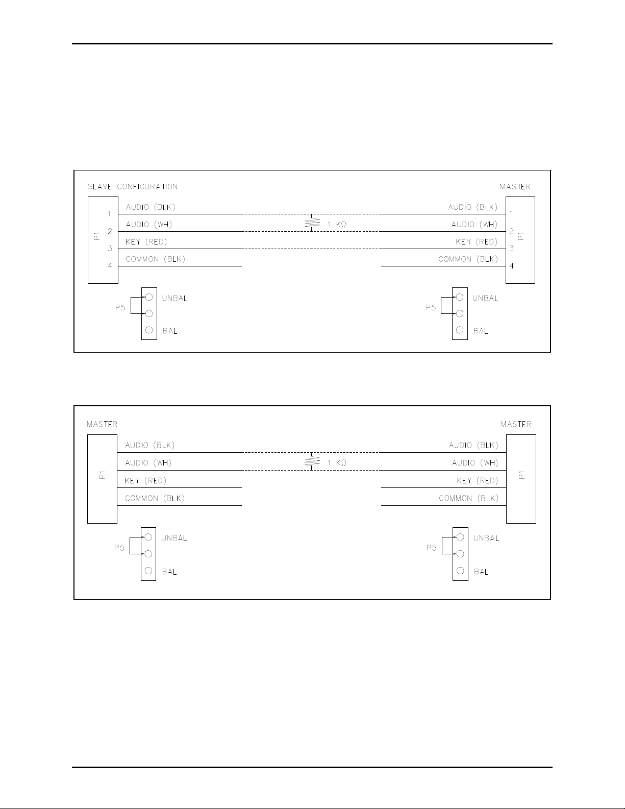
Figure 5. Master/Slave Balanced Configuration
Figure 6. Balanced Common Line Configuration
f:\standard ioms - current release\42004 instr. man uals\42004-307g.doc
03/15
Page 7

Pub. 42004-307G
PAGE INDUSTRIAL INTERCOMS Page 7 of 16
EZ
Optional Footswitch Interface
Interconnection of a GAI-Tronics footswitch to a Listen/Talk or Master unit’s control cable pair will
allow hands-free operation of the unit’s Listen/Talk functions. Refer to Figure 7 for more detail showing
interconnection to system wiring. No internal connection to the unit is needed.
GAI-TRONICS CORPORATION
No. 400-001 - R IGCOM MASTER/S LAVE/COMMON
OFF-ON VOLUME
DATE CODE:
17R9
PUSH TO CALL
CAUTION
RISK OF ELECTRIC
!
SHOCK, DO NOT OPEN!
Figure 7. Footswitch Interconnection
f:\standard ioms - current release\42004 instr. man uals\42004-307g.doc
03/15
Page 8

Pub. 42004-307G
PAGE INDUSTRIAL INTERCOMS Page 8 of 16
EZ
Operation
Combination Speaker Volume/Mute On-Off Switch
Allows the user to adjust the received audio level. The control also allows the unit’s speaker amplifier to
be muted.
Listen/Talk Configured Units
Unit default: Listen mode
To make a page, hold down the Listen/Talk switch in the T
also acts as the microphone. Other units in the system, which are already in the listen mode, will
broadcast the page from their speakers. Releasing the switch deactivates the microphone and returns the
unit to the listen mode.
Master/Slave Configured Units
Master Unit
Unit default: Listen mode
Master unit is in the listen mode and will broadcast any audio generated from an associated Slave unit.
ALK position and talk into the speaker, which
To make a page, hold down the Listen/Talk switch in the T
ALK position and talk into the speaker, which
acts as the microphone. The Master unit’s Listen/Talk switch performs the added function of switching
the Slave unit’s mode from talk to listen. The Slave unit will broadcast the received page from its
speaker.
Releasing the Listen/Talk switch does the following:
Returns the unit to the listen mode by switching the Master unit’s microphone into its original speaker
state
Switches the Slave unit’s mode from listen to talk
Slave Unit
Unit default: Talk mode
The Slave unit is in the talk mode until the Master station operator holds down the press-to-talk switch.
The Slave unit operator does not have to hold down the press-to-talk switch—operation is hands-free.
The Listen/Talk switch is not operable when the unit is configured as a Slave.
Maintenance
Internal Fuse Replac ement
To reduce the risk of fire, replace fuses only with the same type and value as follows:
For Model GC-AC1: 4/10 amp, slo-blo, 250 V, 3AG
For Model GC-DC1: 2 amps, slo-blo, 250 V, 3AG
For Model GC-AC2: 2/10 amp, slo-blo, 250 V, 3AG
f:\standard ioms - current release\42004 instr. man uals\42004-307g.doc
03/15
Page 9

Pub. 42004-307G
PAGE INDUSTRIAL INTERCOMS Page 9 of 16
EZ
Troubleshooting
Periodically check for frayed or cracked wiring, loose connections or signs of corrosion inside and outside
of the unit.
Problem Possible Cause Possible Solution
No audio is received at
unit
Local unit’s speaker volume control is
Unit’s speaker is not turned on
(muted)
turned counterclockwise
Check that local power is available
and speaker volume switch is on.
Adjust volume control to desired
level.
Internal fuse is blown Replace fuse with exact voltage/fuse
rating replacement.
Both paged audio and
received audio is low
Listen/Talk configured
unit can’t
communicate to
another Listen/Talk
configured unit
Short, or low resistance across audio
pair in system cable
Possible system wiring error
Connection of control pair wires to
another Listen/Talk unit. Note: These
wires should be left un-terminated
and insulated.
Correct system wiring.
Correct system wiring.
Acoustic feedback
when making a page
Listen/Talk or Master
Units are positioned too close
together or oriented toward each other
Internal mode switch is set to SLAVE Reposition internal mode switch to
unit is always in the
talk mode
Possible low resistance between the
red/black (control pair) wires within
the unit or system cable.
Slave unit always in
listen mode
Possible low resistance between the
red/black (control pair) wires within
the system cable connected to unit.
Master unit can not
communicate to Slave
Possible open wire/connection of the
control pair wires between units.
unit, but Slave is
communicating to
Master unit
Excessive
static/electromagnetic
interference
System cable is routed too closely to
high voltage, high electromagnetic
sources.
Reorient units away from each other
or reduce speaker volume level.
L/M
ASTER.
Correct system wiring short.
Correct system wiring short.
Correct connections and system
wiring.
Reroute system cable away from high
voltage, high electromagnetic sources.
Use shielded system cable.
f:\standard ioms - current release\42004 instr. man uals\42004-307g.doc
03/15
Page 10

Pub. 42004-307G
PAGE INDUSTRIAL INTERCOMS Page 10 of 16
EZ
Specification s
Electrical
Model GC-AC1
Voltage ............................................................. 108/132 V ac range, 50/60 Hz, (120 V ac, 60 Hz, nominal)
Power consumed (at nominal) .................................. Off (mute)/Standby/Maximum Speaker Out (8 watts)
6 VA, 1.8 W/7.2 VA, 3.6 W/27.6 VA, 22.5 W
Model GC-DC1
Voltage ............................................................................................... 12–16 V dc range, (14 V dc nominal)
Power consumed (at nominal) Off (mute)/Standby/Maximum speaker out (8 watts)
.32 W/1.8 W/18 W
Model GC-AC2
Voltage ............................................................. 207/253 V ac range, 50/60 Hz, (230 V ac, 60 Hz, nominal)
Power consumed (at nominal) Off (mute)/Standby/Maximum speaker out (8 watts)
5.3 VA, 1.8 W/6.9 VA, 4 W/27 VA, 22 W
Amplifier PCBA
Frequency response ................................. 250–8,000 Hz, +0/-3 dB (ref. to 1 kHz), 155 Hz–12 kHz, (-6 dB)
Distortion ........................................................................................... 1% maximum THD @ 1 kHz, 8 watts
Gain. .................................................................... 25 dB nominal (listen mode), 46 dB nominal (talk mode)
Input sensitivity for rated output @1 kHz .................................................................................... 310 mV
Controls ........................................................... Balanced/Unbalanced jumper, L/Master-Slave mode switch
Input impedance ..................................................... 4,800 ohms (listen mode, Bal) (ref. to 1 kHz, Vol. CW)
Hum/noise below rated output. ........................................................................................... -64 dB minimum
RMS
Integral Speaker Assembly
Speaker rating .................................................................................................................. 30 watts maximum
Speaker impedance ............................................................................................................................. 4 ohms
Speaker frequency response ......................................................................... 250–5,000 Hz nominal (-6 dB)
Speaker SPL ........................................................................................................................................ 113 dB
(Test based on IEC 268-5, measured using 8 watt @ 1 meter, pinknoise, wall-mounted)
f:\standard ioms - current release\42004 instr. man uals\42004-307g.doc
03/15
Page 11

Pub. 42004-307G
PAGE INDUSTRIAL INTERCOMS Page 11 of 16
EZ
General
External controls ............................................................... Speaker volume/on-off (mute), listen/talk switch
Internal primary fuse:
GC-AC1 ...................................................................................... 4/10 amp, 250 V, slo-blo (.25 1.25 inch)
GC-DC1 ......................................................................................... 2 amps, 250 V, slo-blo (.25 1.25 inch)
GC-AC2 ...................................................................................... 2/10 amp, 250 V, slo-blo (.25 1.25 inch)
Integral cables:
Power: GC-AC1 ...................... ~9.5-foot, 3-conductor, No. 18 AWG, type SJTW with NEMA 5-15P plug
Power: GC-DC1, GC-AC2 ................................... ~9.5-foot, 4-conductor, 18 AWG, SJOW with wire ends
Audio/Control .............................................. ~9.5-foot, 2 twisted pair cable, 18 AWG, PVC with wire ends
Enclosure ............................................................................................................................... Cast aluminum
Color. .................................................................................................................................. Blue (RAL5017)
Temperature range (Operating/Storage) ............................................... −40º F to +158º F (−40º C to 70º C)
Dimensions .......................................................... 11.20 H 6.97 W 5.45 D (284.5 177.0 138.4 mm)
Recommended: Maximum number of Listen/Talk units per system ......................................................... 20
Maximum number of Slave units per Master unit ............................................................. 1
Shipping weight: GC-AC1 and GC-AC2 ............................................................................ 13.0 lbs. (5.9 kg)
Shipping weight: GC-DC1 .................................................................................................. 12.0 lbs. (5.4 kg)
Unit weight: GC-AC1 and GC-AC2 ................................................................................... 11.1 lbs. (5.1 kg)
Unit weight: GC-DC1 ......................................................................................................... 10.0 lbs. (4.5 kg)
Replac ement Parts
Model Number Description
12604-009 GC-AC1 120 V AC Fuse Kit (10 fuses each)
12604-010 GC-DC1 DC Fuse Kit (10 fuses each)
12604-011 GC-AC2 230V AC Fuse Kit (10 fuses each)
12702-001 AC Board Replacement Kit
12702-002 DC Board Replacement Kit
12504-009 Front Panel Switch Kit
12703-001 Speaker Driver Kit
f:\standard ioms - current release\42004 instr. man uals\42004-307g.doc
03/15
Page 12

Pub. 42004-307G
PAGE INDUSTRIAL INTERCOMS Page 12 of 16
EZ
Appendix A
Interfacin g an EZ Page Sta tion to MS39xx Se ries RigCom Sta tions
The EZ Page station is designed to operate with the MS39xx Series RigCom Stations.
The MS39xx Series uses an unbalanced system for communication and uses the negative of the audio pair
as the ground reference for the control signal. The EZ Page has the ability to operate unbalanced or
balanced. In the balanced system, the audio pair is not ground referenced and the control signal requires a
ground signal with it.
For interoperability between the EZ Page and the MS39xx Series, configure the EZ Page for an
unbalanced system by placing the jumper for P5 in the UNBAL position. No changes are required to the
MS39xx Series. For Master/Slave operation, connect AUDIO– to AUDIO (WH), AUDIO+ to AUDIO
(BLK) and EXT CONT+ to KEY. For common line only the audio wires need connection.
The following are wiring diagrams for the different configurations of a system.
Figure 8. Master/Slave Configuration with EZ Page as Master
f:\standard ioms - current release\42004 instr. man uals\42004-307g.doc
03/15
Page 13

Pub. 42004-307G
PAGE INDUSTRIAL INTERCOMS Page 13 of 16
EZ
Figure 9. Master/Slave Configuration with EZ Page as Slave
Figure 10. Common Line Configuration
f:\standard ioms - current release\42004 instr. man uals\42004-307g.doc
03/15
Page 14

Pub. 42004-307G
PAGE INDUSTRIAL INTERCOMS Page 14 of 16
EZ
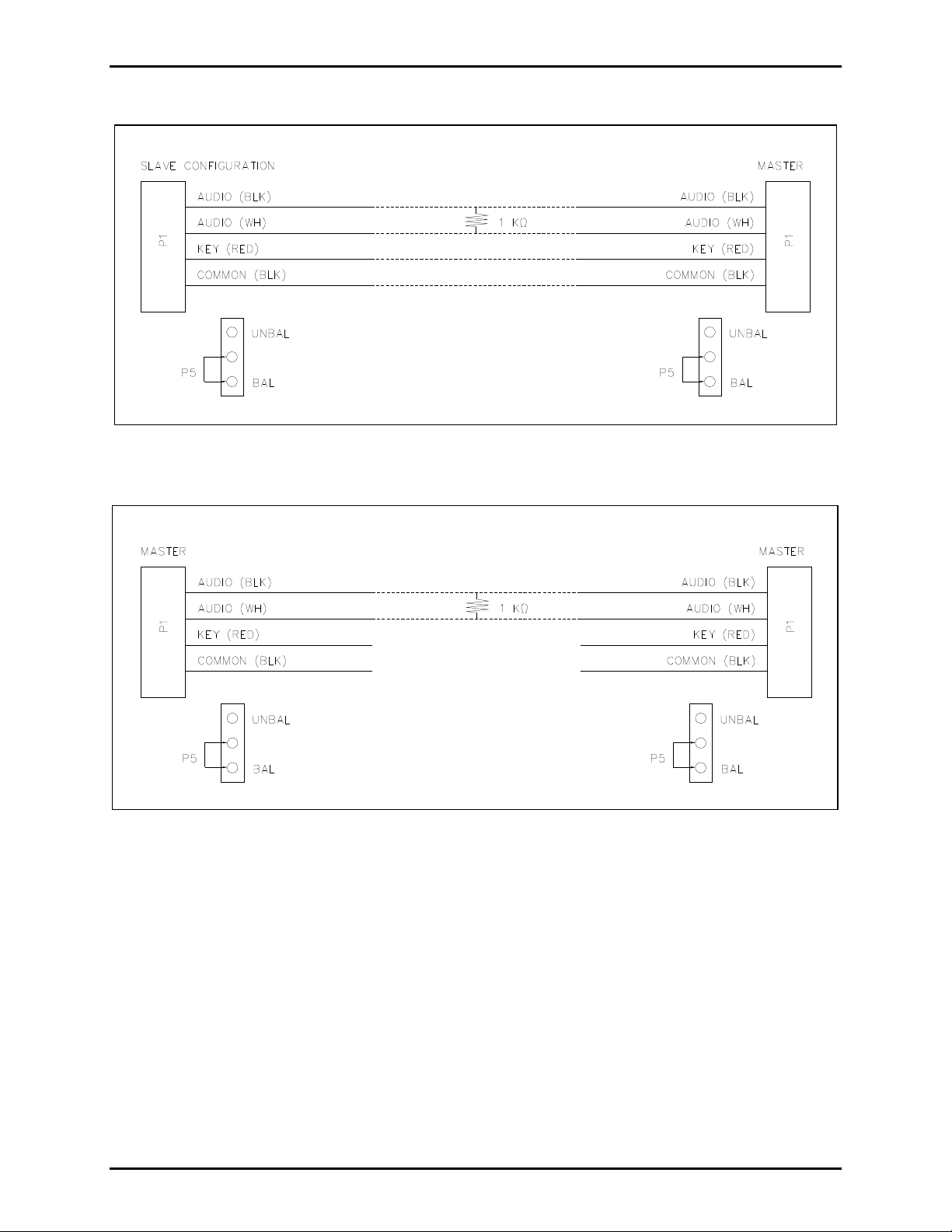
Appendix B
Interfacin g EZ Page Statio ns to Model 400-001 RigCom Sta tions
The EZ Page and Model 400-001 stations are designed to operate either in balanced or unbalanced
systems. An unbalanced system for communication uses the negative of the audio pair as the ground
reference for the control signal. In the balanced system, the audio pair is not ground referenced and the
control signal requires a ground signal.
For interoperability between the Model 400-001 and the EZ Page Series, configure the 400-001 and the
EZ Page identically, balanced or unbalanced, by the location of P5 on the EZ Page and P3 on the Model
400-001.
The following wiring diagrams are for the different configurations for RigCom/EZ Page systems.
Figure 11. Master/Slave Unbalanced Configuration with Model 400-001 Master
Figure 12. Master/Slave Unbalanced Configuration with Model 400-001 as Slave
f:\standard ioms - current release\42004 instr. man uals\42004-307g.doc
03/15
Page 15

Pub. 42004-307G
PAGE INDUSTRIAL INTERCOMS Page 15 of 16
EZ
Figure 13. Unbalanced Common Line Configuration
Figure 14. Master/Slave Balanced Configuration with Model 400-001 as Master
f:\standard ioms - current release\42004 instr. man uals\42004-307g.doc
03/15
Page 16

Pub. 42004-307G
PAGE INDUSTRIAL INTERCOMS Page 16 of 16
EZ
Figure 15. Master/Slave Balanced Configuration with Model 400-001 as Slave
Figure 16. Balanced Common Line Configuration
f:\standard ioms - current release\42004 instr. man uals\42004-307g.doc
03/15
Page 17

Warranty
Equipment. GAI-Tronics warrants for a period of one (1) year from the date of shipment, that any
GAI-Tronics equipment supplied hereunder shall be free of defects in material and workmanship, shall
comply with the then-current product specifications and product literature, and if applicable, shall be fit
for the purpose specified in the agreed-upon quotation or proposal document. If (a) Seller’s goods prove
to be defective in workmanship and/or material under normal and proper usage, or unfit for the purpose
specified and agreed upon, and (b) Buyer’s claim is made within the warranty period set forth above,
Buyer may return such goods to GAI-Tronics’ nearest depot repair facility, freight prepaid, at which time
they will be repaired or replaced, at Seller’s option, without charge to Buyer. Repair or replacement shall
be Buyer’s sole and exclusive remedy. The warranty period on any repaired or replacement equipment
shall be the greater of the ninety (90) day repair warranty or one (1) year from the date the original
equipment was shipped. In no event shall GAI-Tronics warranty obligations with respect to equipment
exceed 100% of the total cost of the equipment supplied hereunder. Buyer may also be entitled to the
manufacturer’s warranty on any third-party goods supplied by GAI-Tronics hereunder. The applicability
of any such third-party warranty will be determined by GAI-Tronics.
Services. Any services GAI-Tronics provides hereunder, whether directly or through subcontractors,
shall be performed in accordance with the standard of care with which such services are normally
provided in the industry. If the services fail to meet the applicable industry standard, GAI-Tronics will
re-perform such services at no cost to buyer to correct said deficiency to Company's satisfaction provided
any and all issues are identified prior to the demobilization of the Contractor’s personnel from the work
site. Re-performance of services shall be Buyer’s sole and exclusive remedy, and in no event shall GAITronics warranty obligations with respect to services exceed 100% of the total cost of the services
provided hereunder.
Warranty Periods. Every claim by Buyer alleging a defect in the goods and/or services provided
hereunder shall be deemed waived unless such claim is made in writing within the applicable warranty
periods as set forth above. Provided, however, that if the defect complained of is latent and not
discoverable within the above warranty periods, every claim arising on account of such latent defect shall
be deemed waived unless it is made in writing within a reasonable time after such latent defect is or
should have been discovered by Buyer.
Limitations / Exclusions. The warranties herein shall not apply to, and GAI-Tronics shall not be
responsible for, any damage to the goods or failure of the services supplied hereunder, to the extent
caused by Buyer’s neglect, failure to follow operational and maintenance procedures provided with the
equipment, or the use of technicians not specifically authorized by GAI-Tronics to maintain or service the
equipment. THE WARRANTIES AND REMEDIES CONTAINED HEREIN ARE IN LIEU OF AND
EXCLUDE ALL OTHER WARRANTIES AND REMEDIES, WHETHER EXPRESS OR IMPLIED BY
OPERATION OF LAW OR OTHERWISE, INCLUDING ANY WARRANTIES OF
MERCHANTABILITY OR FITNESS FOR A PARTICULAR PURPOSE.
Return Policy
If the equipment requires service, contact your Regional Service Center for a return authorization number
(RA#). Equipment should be shipped prepaid to GAI-Tronics with a return authorization number and a
purchase order number. If the equipment is under warranty, repairs or a replacement will be made in
accordance with the warranty policy set forth above. Please include a written explanation of all defects to
assist our technicians in their troubleshooting efforts.
Call 800-492-1212 (inside the USA) or 610-777-1374 (outside the USA) for help identifying the
Regional Service Center closest to you.
(Rev. 10/06)
 Loading...