

Page 1

Pub. 42004-485A
GAI-TRONICS® CORPORATION
A HUBBELL COMPANY
Elemec3 Portal
User Manual – Version 1.2
T ABLE OF C ONTENTS
Confidentiality Notice .....................................................................................................................1
Overview ..........................................................................................................................................1
Installing and Registering the Software .........................................................................................1
Installation Requirements ...................................................................................................................... 1
Installation Procedure ............................................................................................................................ 1
Host Computer IP Address .............................................................................................................4
Running the Portal Application .....................................................................................................4
Connecting to an Elemec3 Controller ................................................................................................. 5
Elemec Portal Security....................................................................................................................7
Defining Users ......................................................................................................................................... 7
User Levels ........................................................................................................................................................... 7
User Types ............................................................................................................................................................ 7
Editing Users ........................................................................................................................................... 7
Administration Utility Screen .........................................................................................................8
Restart System Button .......................................................................................................................... 10
MSG Button ........................................................................................................................................... 11
System Messages ................................................................................................................................................ 11
Tick Tones Button ................................................................................................................................. 12
Options Button ...................................................................................................................................... 13
System ................................................................................................................................................................. 13
Connection Settings ............................................................................................................................................ 14
Date / Time ......................................................................................................................................................... 14
Sound .................................................................................................................................................................. 14
System Snapshots ............................................................................................................................................... 14
Manage Users Button ........................................................................................................................... 15
User Management Screen ................................................................................................................................... 15
Manage Users Tab .............................................................................................................................................. 15
Manage Permissions Tab .................................................................................................................................... 16
System Snapshots Button ..................................................................................................................... 17
System Snapshots ............................................................................................................................................... 17
Switch User ......................................................................................................................................................... 18
Disconnect .......................................................................................................................................................... 18
Administration Button .......................................................................................................................... 19
Upload New Configuration ................................................................................................................................. 20
GAI-Tronics Corporation 400 E. Wyomissing Ave. Mohnton, PA 19540 USA
610-777-1374 800-492-1212 Fax: 610-796-5954
V
ISIT WWW.GAI-TRONICS.COM FOR PRODUCT LITERATURE AND MANUALS
Page 2

TABLE OF CONTENTS
Stored Configurations ......................................................................................................................................... 22
Set as Running Configuration ............................................................................................................................. 22
Set As Default Configuration .............................................................................................................................. 23
Remove Configuration ........................................................................................................................................ 23
Download Configuration .................................................................................................................................... 24
Software Versions ............................................................................................................................................... 25
Event Status Button .............................................................................................................................. 26
Audio Mix #1, Audio Mix #2 ............................................................................................................................. 26
Reported Events .................................................................................................................................................. 27
Fault Status Button ............................................................................................................................... 28
Fault Notification Panel ...................................................................................................................................... 28
System Status LED Indicator on E3 Controller .................................................................................................. 29
Scope................................................................................................................................................................... 29
Status Filter ......................................................................................................................................................... 29
Fault Reporting Configuration in Elemec3 ....................................................................................................... 30
Amplifier Status Button ....................................................................................................................... 31
Scope................................................................................................................................................................... 31
Amplifier Status List ........................................................................................................................................... 32
Status Filter ......................................................................................................................................................... 32
I/O Status Button .................................................................................................................................. 33
Scope................................................................................................................................................................... 34
Input Status/Output Status .................................................................................................................................. 34
Status Filter ......................................................................................................................................................... 34
System Flags Button ............................................................................................................................. 35
Scope................................................................................................................................................................... 35
System Flag Status / User Flag Status ................................................................................................................ 35
Status Filter ......................................................................................................................................................... 35
GAI-Tronics Corporation 400 E. Wyomissing Ave. Mohnton, PA 19540 USA
610-777-1374 800-492-1212 Fax: 610-796-5954
V
ISIT WWW.GAI-TRONICS.COM FOR PRODUCT LITERATURE AND MANUALS
Page 3

Pub. 42004-485A
GAI-TRONICS® CORPORATION
A HUBBELL COMPANY
Elemec3 Portal
User Manual – Version 1.2
Confidential ity Notice
This manual is provided solely as an operational, installation, and maintenance guide and contains sensitive
business and technical information that is confidential and proprietary to GAI-Tronics. GAI-Tronics
retains all intellectual property, other rights in or to the information contained herein, and such information
may only be used in connection with the operation of your GAI-Tronics product or system. This manual
may not be disclosed in any form, in whole or in part, directly or indirectly, to any third party.
Overview
The Elemec3 (E3) Portal application runs on any PC connected to the same Ethernet network as the E3
Controller. This software package is used to upload and download system configuration files to/from the
E3 System Controller. The Portal application is not used to make changes to the system configuration.
Changes are made using the Elemec3 Console application. Refer to GAI-Tronics Pub. 42004-483 for
information on system programming.
The Portal application is also used to monitor system activity and status reporting of E3 system
components. System status is displayed in real time. Selection buttons are provided allowing the
operator to filter the information by equipment category or event types. Multiple PCs can run the E3
Portal application, providing more than one monitoring location.
OTE: Only a single instance of the Portal application can be connected to one E3 Controller at a time,
N
and only a single instance of the Portal application can run on one PC at a time. In E3 systems containing
redundant controllers, the user must disconnect from Controller “A” before connecting to Controller “B”.
Installing and R egistering the Software
Installa tion Requi rements
Prior to installing the Elemec3 Portal application, the host com puter must have Adobe AIR installed.
The software is free, and the newest version can be downloaded and installed from Adobe’s internet
website, http://get.adobe.com/air
After installing Adobe AIR, the E3 Portal application can be installed as described below.
Installation Procedure
1. Insert the installation CD into the CD drive or insert a USB storage device containing the Elemec3
Portal application installation file.
.
GAI-Tronics Corporation 400 E. Wyomissing Ave. Mohnton, PA 19540 USA
610-777-1374 800-492-1212 Fax: 610-796-5954
V
ISIT WWW.GAI-TRONICS.COM FOR PRODUCT LITERATURE AND MANUALS
Page 4
Pub. 42004-485A
Elemec3 Portal User Manual Ver s io n 1.2 Page 2 of 35
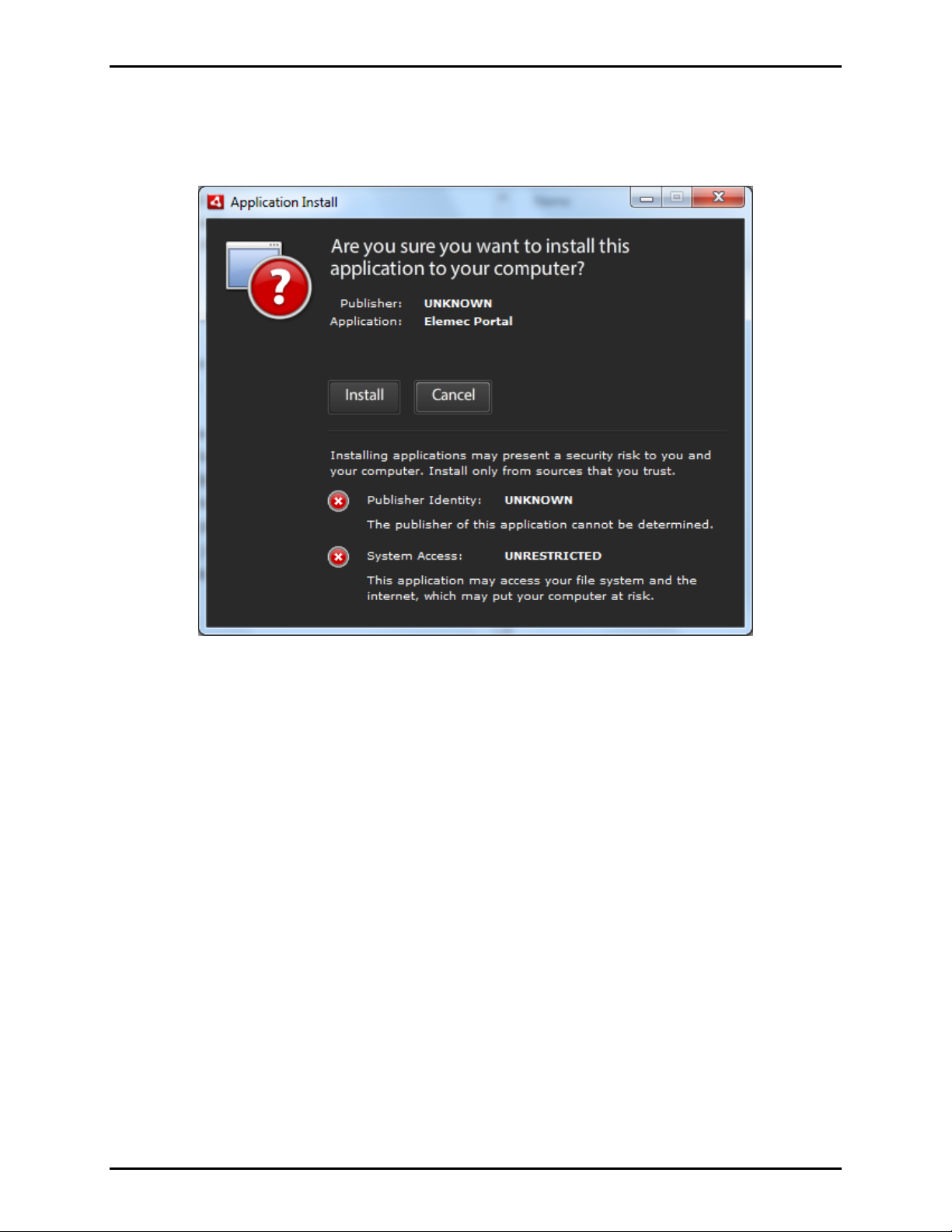
2. Use Windows Explorer to navigate to the CD or other installation file location and double click on the
ElemecPortal file.
3. When the screen below appears, click the I
NSTALL button.
Figure 1.
f:\standard ioms - current release\ 42004 instr. manuals\42004-485a.docx
02/14
Page 5
Pub. 42004-485A
Elemec3 Portal User Manual Ver s io n 1.2 Page 3 of 35
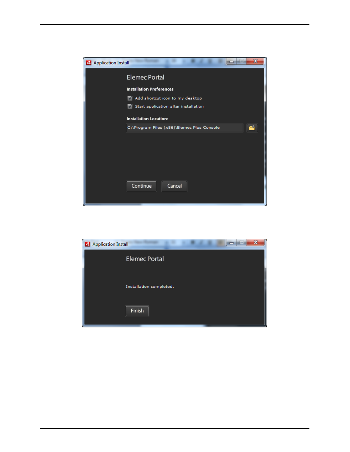
4. Select the Installation Preferences using the check boxes as shown in Figure 2 and click the
ONTINUE button. The default installation location is displayed.
C
Click the F
Figure 2.
INISH button to complete the installation.
Figure 3.
f:\standard ioms - current release\ 42004 instr. manuals\42004-485a.docx
02/14
Page 6
Pub. 42004-485A
Elemec3 Portal User Manual Ver s io n 1.2 Page 4 of 35
Host Computer IP Address
By default, the E3 Controller IP address is factory set to the static IP address 192.168.1.25 with a subnet
mask of 255.255.255.0. If A/B redundant controllers are being used in the system, the “A” Controller
will have the default IP address of 192.168.1.25. The “B” Controller will have the default IP address of
192.168.1.26.
Depending on the network configuration, either static IP or DHCP can be used. If a DNS server is
available, connection can be made using the Elemec3 host name.
Consult with your network administrator for proper configuration of the host computer and Elemec3
system(s).
Running th e P ortal Application
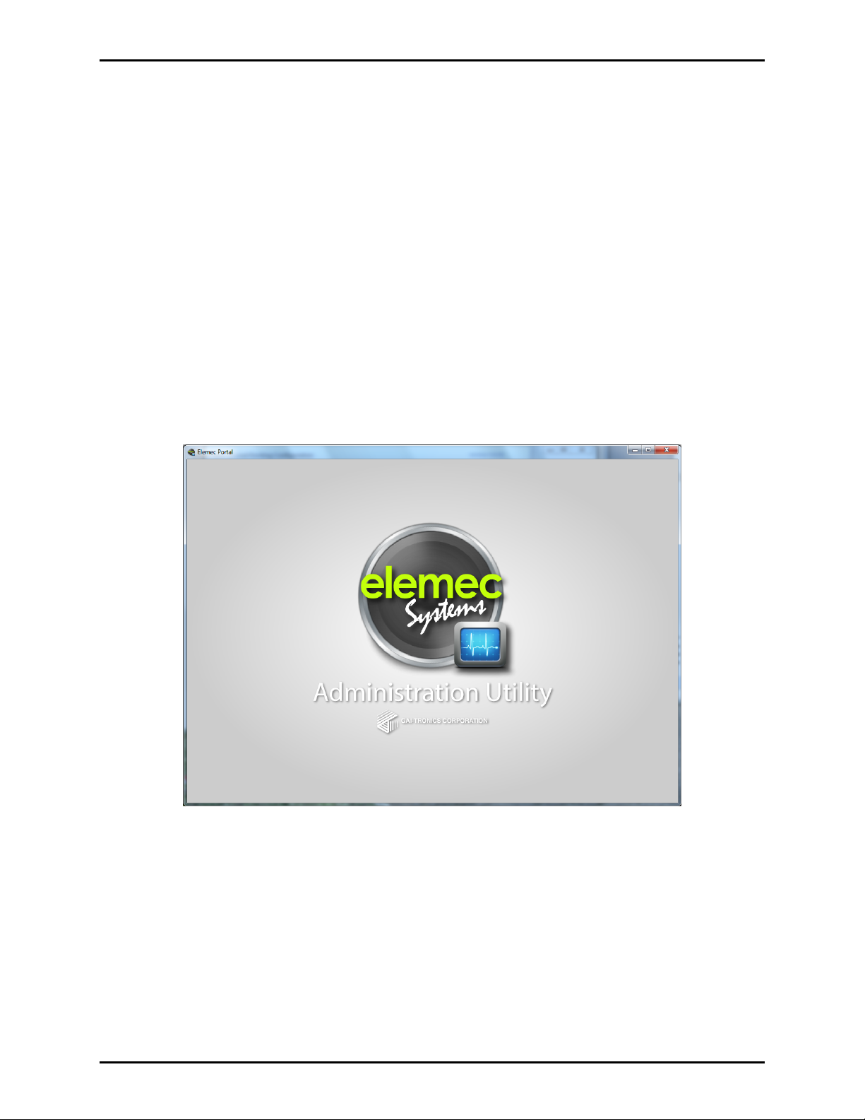
The Administration Utility Welcome screen shown in Figure 4 appears momentarily as the program is
starting.
Figure 4. Administration Utility Welcome screen
f:\standard ioms - current release\ 42004 instr. manuals\42004-485a.docx
02/14
Page 7
Pub. 42004-485A
Elemec3 Portal User Manual Ver s io n 1.2 Page 5 of 35
Connecting t o an Elemec3 Controller
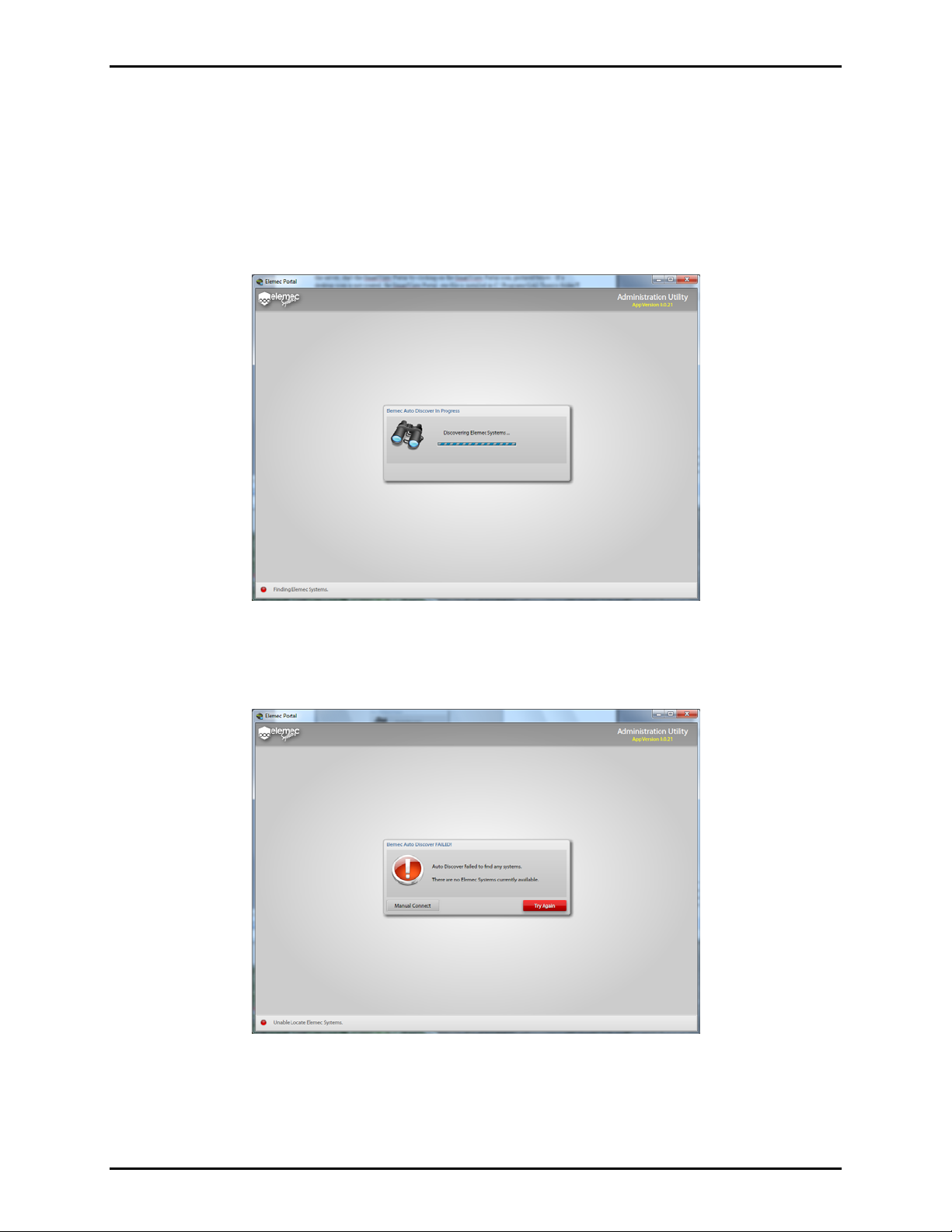
The program has an auto-discovery feature that will search for any Elemec3 Controllers on the network.
By default, the auto-discovery feature launches automatically when the program is started. The following
screen appears during the discovery process. Optionally, the auto-discovery feature can be disabled.
OTE: The maximum number of simultaneous Portal connections to an E3 controller is 10. If 10 users
N
are connected to an E3 controller, subsequent connection requests will be rejected.
Figure 5. Elemec Auto Discovery in Progress screen
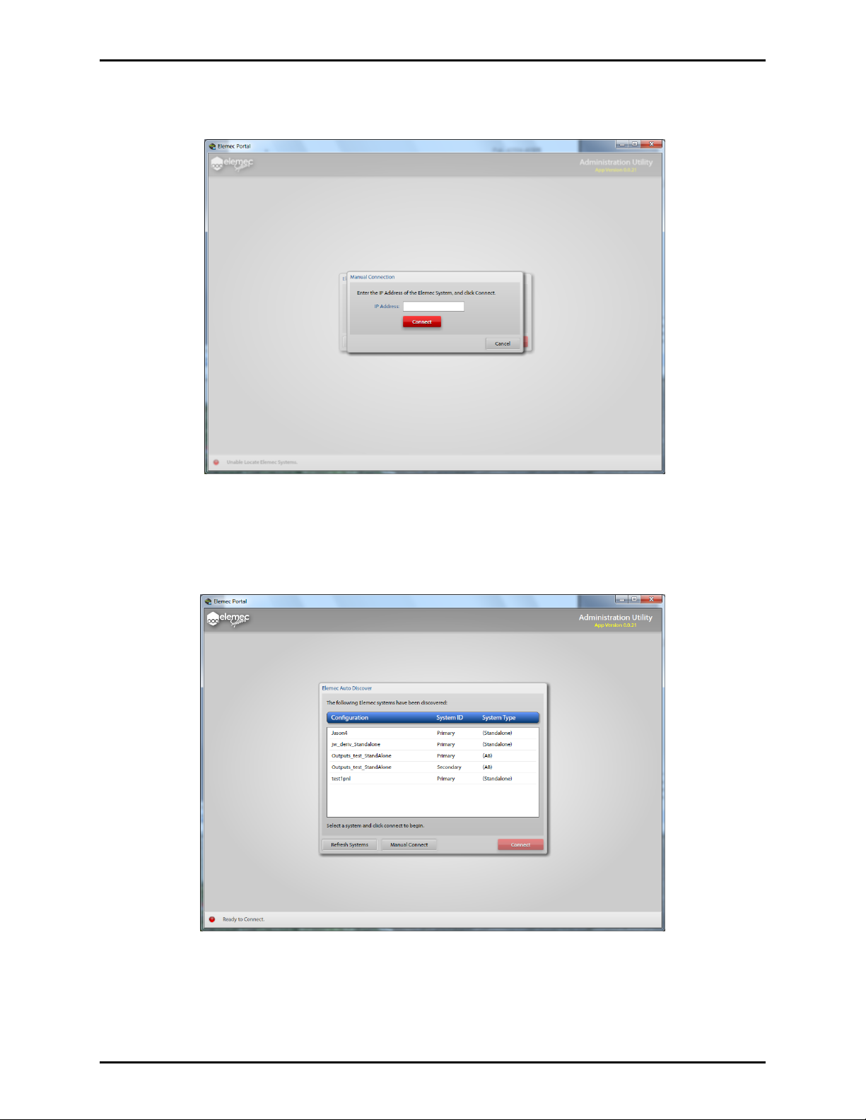
If no E3 controllers (or systems) are found, the Elemec Auto Discover FAILED screen as shown in Figure
6 will appear.
Figure 6. Elemec Auto Discover FAILED screen
To manually connect, click on the M
f:\standard ioms - current release\ 42004 instr. manuals\42004-485a.docx
02/14
ANUAL CONNECT button.
Page 8
Pub. 42004-485A
Elemec3 Portal User Manual Ver s io n 1.2 Page 6 of 35
Enter the IP Address/Host Name of the E3 system when the screen shown in Figure 7 below appears, and
click the red C
ONNECT button.
.
Figure 7. Manual Connection screen
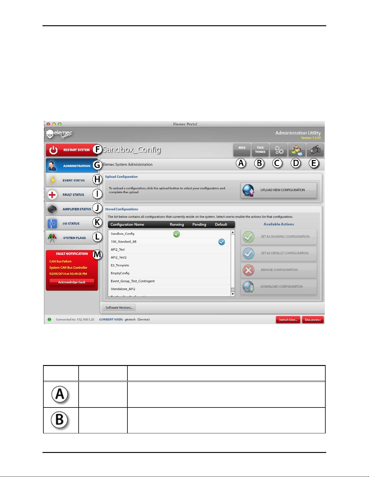
Upon successful auto discovery of E3 systems, the scr een shown in the exam ple i n Figure 8 appears.
Each entry represents a different E3 Controller. The names that appear in the list are the names of the
configuration files that are currently running on an E3 Controller.
Figure 8. Elemec Auto Discover Screen
Select the desired controller from the list and click the red C
referred to as the “local” system.
f:\standard ioms - current release\ 42004 instr. manuals\42004-485a.docx
02/14
ONNECT button. The connected system is
Page 9

Pub. 42004-485A
Elemec3 Portal User Manual Ver s io n 1.2 Page 7 of 35
Elemec P ortal Security
Access to and functionality of the Elemec3 Portal application is controlled through a system of user
logins and security features. After a successful connection to the Elemec3 system, users must enter their
username and password to gain access to viewing the system status and performing any type of system
maintenance.
On any new system, a default Administrator-level user account is provided on the E3 controller with
access to create and configure the system’s other user accounts. The initial login is:
Default username: admin
Default password: password
To maintain the integrity of the E3 controller security, it is highly recommended that this account be
removed once all the necessary users have been set up by the on-site administrator.
Refer to the Manage Users screen on page 15 of this manual for more information.
Defining Users
User Levels
The five user levels listed from lowest to highest permission levels are:
Guest (no password required) – view-only access to system status information.
Viewer – Configurable permissions.
Operator – Configurable permissions.
Maintenance – Configurable permissions.
Administrator – Configurable permissions and can configure permissions for other levels (default).
User Types
In addition to the different user levels, there are two user types: Public and Private:
Public – cannot change their password. By default, passwords must be changed by an Administrator.
For example, maintenance users can be assigned a common username and password.
Private – can change their password. Private user types are recommended for higher access levels.
There are a few key rules regarding user management:
Users can only edit permissions below their own user level.
User levels given permission to edit users can manage user level, access and passwords of any user.
Private users can change their own password, regardless of user editing permissions.
Changes to permissions of a user level will log off all connected users at that level.
Editing Users
User permissions are edited through the User Management window shown in Figure 22 on page 15. The
current permissions are displayed upon opening. To edit any specific level, click EDIT at the top of the
column. Refer to the “Manage Users” section on page 15 for more information.
f:\standard ioms - current release\ 42004 instr. manuals\42004-485a.docx
02/14
Page 10
Pub. 42004-485A
Elemec3 Portal User Manual Ver s io n 1.2 Page 8 of 35
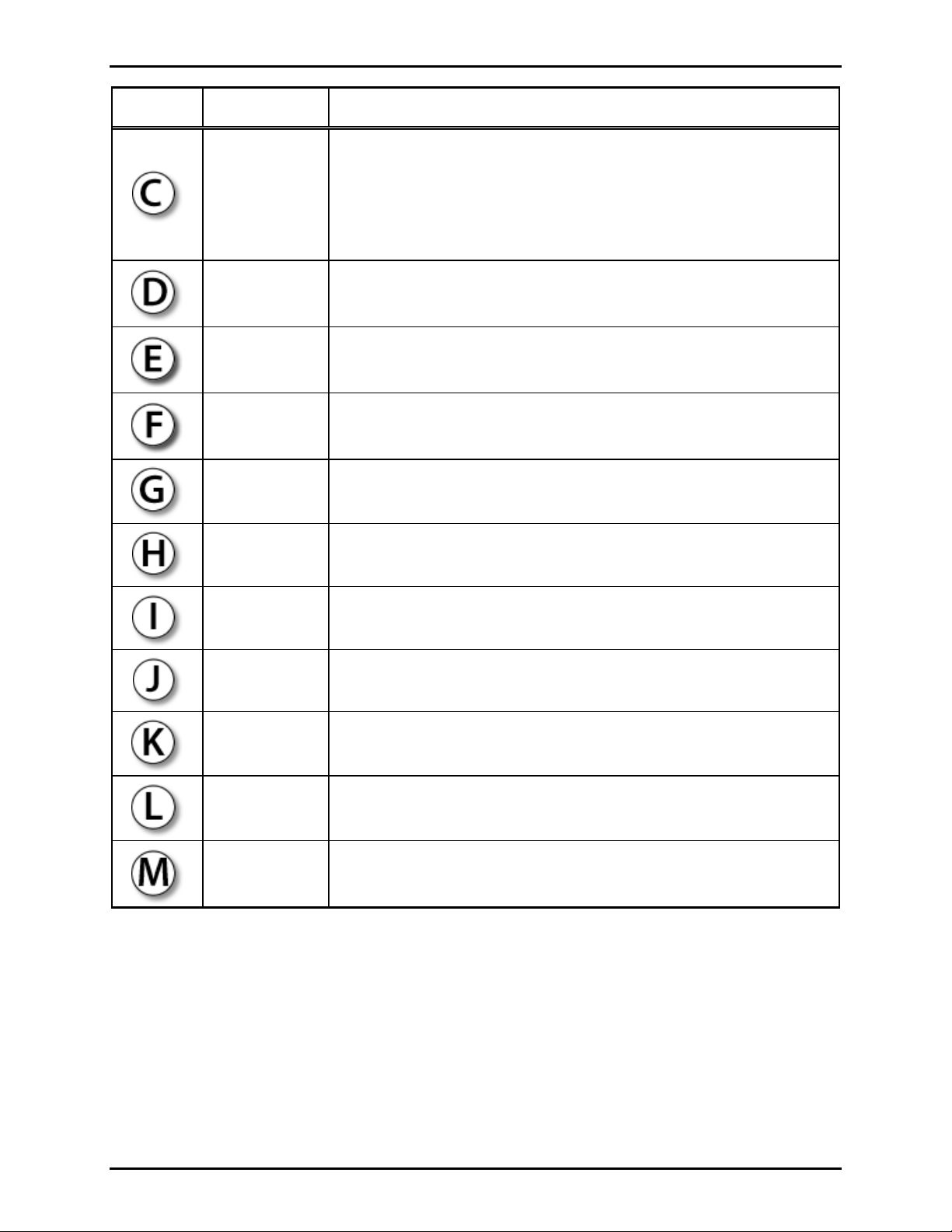
Administration Utility Screen
Upon connecting to an E3 Controller, the Administration Utility screen appears. An example appears in
Figure 9 below. This screen provides the “gateway” access to Elecmec3 system features. Its
functionality depends on the level and permissions of the current user. The current user and the user level
are always identified at the bottom of the screen. The user can be switched using the S
button.
The function of the buttons indicated with “A” through “M” in the example in Figure 9 below are defined
in Table 1 and examples of their use are included in this manual.
WITCH USER
Figure 9. Elemec3 System Administration Utility screen
Table 1. Elecmec3 System Administration Utility Screen Button Functions & Fault Notification Panel
Notation Name Description
Messages
(MSG) Button
Tick Tones
Button
f:\standard ioms - current release\ 42004 instr. manuals\42004-485a.docx
02/14
Displays any system messages. System messages are notifications that
do not qualify as faults or events. Refer to page 11 for further
information.
Displays the Tick Tones screen. The Tick Tone is generally used for
testing the speakers. See “Tick Tone” section of this manual on page
12 for details.
Page 11
Pub. 42004-485A
Elemec3 Portal User Manual Ver s io n 1.2 Page 9 of 35
Notation Name Description
Allows the user to select options for:
Network connections to the system
Options Button
Time and date format
Playing a sound file for fault notification
See “Options” section of this manual on page 13 for details.
Manage Users
Button
Snapshots
Button
Restart System
Button
Administration
Button
Event Status
Button
Fault Status
Button
Amplifier
Status Button
Displays the Manage Users screen. This button is enabled and disabled
based on the permissions assigned to the current user. Refer to page 15
for further information.
Displays the Confirm System Snapshots screen. If the current user has
permission, the option to download snapshots is presented. Refer to the
“Snapshots Button” section on page 17.
Displays the Confirm Restart screen. When restarted, connection to the
E3 Controller will be lost. Refer to the “Restart System Button” section
on page 10.
Displays the Elemec System Administration screen. Refer to the
“Administration Button” section on page 19.
Displays the Event Status screen. See the “Event Status Button”
section on page 26.
Displays the Fault Status screen. See “Fault Status Button” section on
page 28 of this manual for details.
Displays the Amplifier Status screen. See “Amplifier Status Button”
section of this manual on page 31 for details.
I/O Status
Button
Displays the I/O Status screen. See “I/O Status Button” section on page
33 of this manual for details.
System Flags
Button
Displays the System Flag screen. See “System Flag Button” section on
page 35 of this manual for details.
Fault
Notification
Panel
f:\standard ioms - current release\ 42004 instr. manuals\42004-485a.docx
02/14
The most recent unacknowledged fault will be displayed in the Fault
Notification Panel accompanied by an audible tone. Refer to page 28.
Page 12
Pub. 42004-485A
Elemec3 Portal User Manual Version 1.2 Page 10 of 35
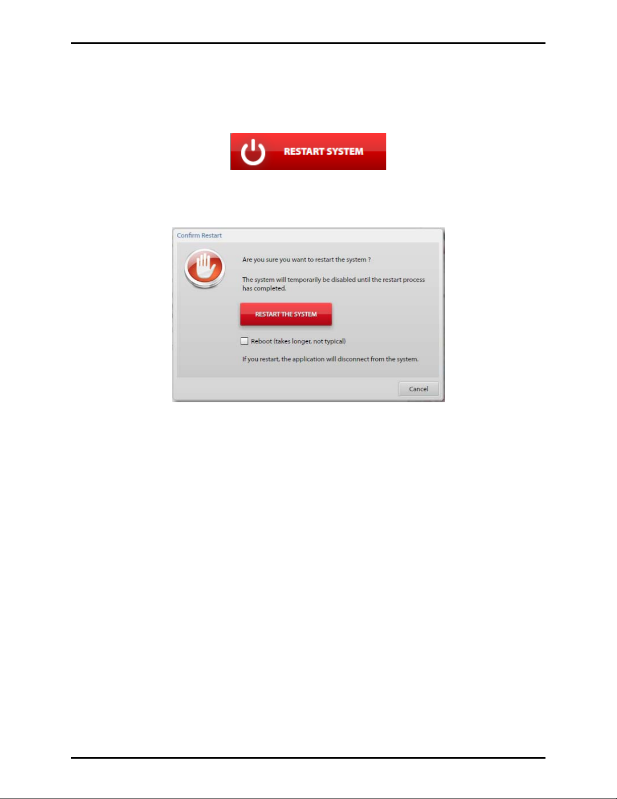
Restart System Button
The RESTART SYSTEM button is always displayed as red.
OTE: The ability to restart the system is dependent on the user’s permission setting.
N
Figure 10. Restart System button
Clicking the
RESTART SYSTEM button displays the Confirm Restart window shown in Figure 11.
Figure 11. Confirm Restart screen
Restart the System – Click to restart the E3 Controller. R
ESTART THE SYSTEM only restarts the Elemec
processes. When the system is restarted, all users will be logged off.
Reboot Option – When checked, clicking the R
ESTART THE SYSTEM button will cause an operating
system reboot in addition to the Elemec processes.
f:\standard ioms - current release\ 42004 instr. manuals\42004-485a.docx
02/14
Page 13
Pub. 42004-485A
Elemec3 Portal User Manual Version 1.2 Page 11 of 35
MSG Button
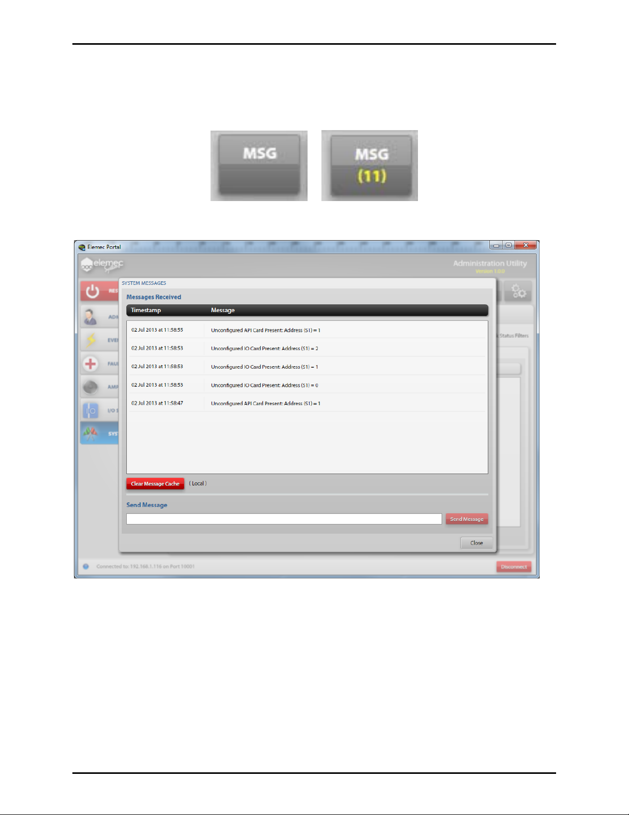
Click the MSG button to display the System Messages screen as shown in Figure 13. The number in
yellow on the button represents the number of unread messages.
Figure 12. MSG button
Figure 13. System Messages screen
System Messages
Messages Received – Notifications that do not qualify as an event or a fault. They are time and datestamped and typically this window displays hardware that is installed but not defined in the system
configuration.
Clear Message Cache – Click to remove messages locally. N
OTE: All messages will be removed upon
system startup.
Send Message – A Portal user may send messages to other connected Portal users by typing a message in
the Send Message box and clicking the S
f:\standard ioms - current release\ 42004 instr. manuals\42004-485a.docx
02/14
END MESSAGE button.
Page 14

Pub. 42004-485A
Elemec3 Portal User Manual Version 1.2 Page 12 of 35
Tick T ones Button
Click the TICK TONES button to display the Send Tick Tone window shown below.
Figure 14. Tick Tones button
The Send Tick Tones window allows you to play the Tick Tone to the selected zone and is generally used
for testing the speakers.
OTE: The Tick Tone is specified using the Elemec3 Console application.
N
Figure 15. Send Tick Tones screen
Select the zone, using the Zones drop down list.
Figure 16. Send Tick Tones Drop Down List
Clicking the green triangular ‘Play’ button broadcasts the Tick Tone to the selected zone.
Figure 17. Send Tick Tones – Play and Stop Buttons
Tick Tone Status – the zone is shown in red when the Tick Tone is being broadcast.
f:\standard ioms - current release\ 42004 instr. manuals\42004-485a.docx
02/14
Page 15
Pub. 42004-485A
Elemec3 Portal User Manual Version 1.2 Page 13 of 35
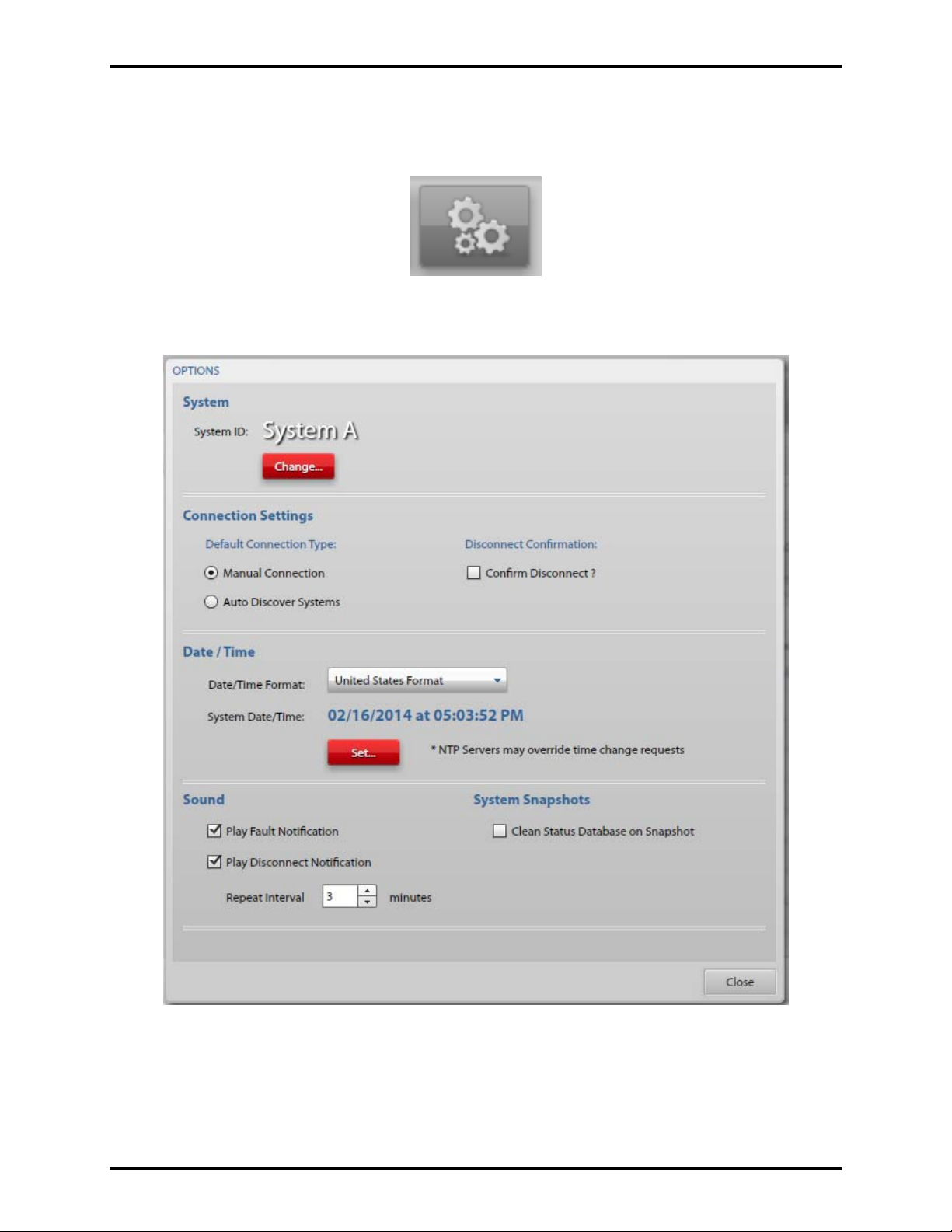
Options Button
Click the Options button to display the Options window shown in Figure 19 below.
Figure 18. Options button
Figure 19. Options screen
System
System ID – Displays the system ID: Standalone, Primary (A), or Secondary (B).
Change – Changes which system is being displayed.
f:\standard ioms - current release\ 42004 instr. manuals\42004-485a.docx
02/14
Page 16

Pub. 42004-485A
Elemec3 Portal User Manual Version 1.2 Page 14 of 35
Connection Settings
Default Connection Type
Manual Connection – When selected, the user must enter the IP Address/Host Name of the E3
system.
Auto-Discover Systems – When selected, the user’s computer will search for any E3 systems
connected to the network.
Discover Interval – Sets the amount of time to wait for a response for each network controller
throughout the auto-discover process.
Confirm Disconnect – When checked, confirmation will be required for disconnection.
Date / Time
Date/Time Format – Use drop down box to select U.S. or U.K. time format.
System Date/Time – Displays the current date and time in the current format.
Set – Click the red S
the Set Date calendar and the time from the Set Time fields, and then click S
ET button to view the Set Elemec Controller Date/Time screen. Select the date from
ET. This is not necessary if
an NTP Server is specified in the configuration.
OTE: The system will automatically restart after setting the Date/Time.
N
Figure 20. Set Elemec Controller Date/Time screen
Sound
Play Fault Notification – When checked, a notification tone will be played locally when a fault is
reported.
Play Desconnect Notification – When selected, a notification tone will be played when the connection to
the E3 controller is closed. The tone will continue to repeat at the interval specified by the Repeat
Interval. The tone will not play if the user has manually disconnected from the controller by clicking the
ISCONNECT button.
D
Repeat Interval – specifies the interval in minutes that the Fault Notification tone will be repeated.
System Snapshots
Clean Status Database on Snapshot – When checked, the database is cleaned to remove all records that
have been previously cleared and/or acknowledged. Each clean operation will create an entry in the
Admin Log identifying the initiator by user and IP address.
f:\standard ioms - current release\ 42004 instr. manuals\42004-485a.docx
02/14
Page 17

Pub. 42004-485A
Elemec3 Portal User Manual Version 1.2 Page 15 of 35
Manage Users Button
Click MANAGE USERS button on the Administration Utility screen to display the User Management
screen shown in Figure 22 below.
Figure 21. Manage Users button
User Management Screen
The User Management screen provides access to both the Manage Users and Manage Permissions tabs.
Manage Users Tab
From the Manage Users tab, select a specific user from the list on the left to view that user’s details on the
right. The user’s type and level may be edited by selecting the E
DIT USER button.
To edit the user’s password, click the red C
HANGE PASSWORD button.
Figure 22. User Management screen (with Manage Users tab selected)
f:\standard ioms - current release\ 42004 instr. manuals\42004-485a.docx
02/14
Page 18

Pub. 42004-485A
Elemec3 Portal User Manual Version 1.2 Page 16 of 35
Manage Permissions Tab
From the Manage Permissions tab, click the EDIT button to edit permissions for a specific user level, and
check the appropriate permissions.
Figure 23. Manage Permissions screen
f:\standard ioms - current release\ 42004 instr. manuals\42004-485a.docx
02/14
Page 19

Pub. 42004-485A
Elemec3 Portal User Manual Version 1.2 Page 17 of 35
System Snapshots Button
Click the SYSTEM SNAPSHOTS button to display the Confirm System Snapshot window shown in Figure
25.
Figure 24. System Snapshots button
YSTEM SNAPSHOTS button allows a user to download or to view system snapshots saved to the
The S
local computer. Only users with permission to download configurations can take a snapshot of the
current system.
System Snapshots
A System Snapshot contains the available status at a specific point in time. Additionally, the snapshot
includes two log files: the Admin Log and the Sys Log.
Admin Log – The Admin Log contains all information pertaining to user interaction with the system.
Sys Log – The Sys Log contains operating system messages.
Figure 25. Confirm System Snapshot screen
Download Snapshot – clicking on D
OWNLOAD SNAPSHOT provides a listing of logged events at a
specific point in time as a documentation or troubleshooting tool. It can be saved to the local computer
for future reference.
View Snapshot – clicking on VIEW SNAPSHOT displays an existing Snapshot stored on the local
computer.
f:\standard ioms - current release\ 42004 instr. manuals\42004-485a.docx
02/14
Page 20

Pub. 42004-485A
Elemec3 Portal User Manual Version 1.2 Page 18 of 35
Switch User
Click the S
WITCH USER button, which is always located on the lower right of the Administration Utility
screen, to login as a different user without disconnecting from the system.
Figure 26. Switch User button
Disconnect
Click the D
ISCONNECT button, which is always located on the lower right of the Administration Utility
screen, to close the network connection to the E3 Controller.
Figure 27. Disconnect button
The Connection Closed screen is displayed.
Figure 28. Connection Closed screen
f:\standard ioms - current release\ 42004 instr. manuals\42004-485a.docx
02/14
Page 21

Pub. 42004-485A
Elemec3 Portal User Manual Version 1.2 Page 19 of 35
Administratio n Button
Click the ADMINISTRATION button on the Administration Utility screen to display the Elemec System
Administration screen shown in Figure 29. The A
screen is currently selected.
This screen displays the choices among the configuration options available if the user has the appropriate
permissions. If the user does not have the appropriate permissions, the button is disabled.
DMINISTRATION button turns blue to indicate which
Figure 29. Elemec System Administration screen
f:\standard ioms - current release\ 42004 instr. manuals\42004-485a.docx
02/14
Page 22

Pub. 42004-485A
Elemec3 Portal User Manual Version 1.2 Page 20 of 35
Upload Ne w Configur ation Click the U
PLOAD NEW CONFIGURATION button to display the Configuration Upload screen shown in
Figure 30 below.
Select the location of the configuration to be uploaded.
Upload From:
Elemec Bridge – A storage location on the host computer shared with the Elemec3 Console
application.
Custom – Use the B
ROWSE button to select the folder containing the configuration(s). When
selected, only valid configurations will be displayed.
Figure 30. Configuration Upload screen
Select a configuration from the Available Configurations list. When selected, the configuration is
identified at the Configuration to Upload field near the bottom of the screen.
f:\standard ioms - current release\ 42004 instr. manuals\42004-485a.docx
02/14
Page 23

Pub. 42004-485A
Elemec3 Portal User Manual Version 1.2 Page 21 of 35
Click the UPLOAD button, and the Confirm Configuration Upload screen is displayed as shown in Figure
31.
Click U
Restart prior to clicking U
PLOAD CONFIGURATION to continue. If desired, check the Set as Running Configuration and
PLOAD CONFIGURATION.
Set as Running Configuration and Restart – when checked, the configuration becomes the running
configuration and the system is restarted.
Figure 31. Confirm Configuration Upload screen
Upon successful upload of the configuration file, the screen shown in Figure 32 will be displayed.
Figure 32. Configuration Upload Succeeded screen
f:\standard ioms - current release\ 42004 instr. manuals\42004-485a.docx
02/14
Page 24

Pub. 42004-485A
Elemec3 Portal User Manual Version 1.2 Page 22 of 35
Stored Configurations
The Stored Configurations Panel shown in Figure 33 lists the availabl e config ura ti ons stored on the
connected E3 Controller. Configurations are created using the Elemec3 Console application.
Figure 33. Stored Configurations screen
Running – a checkmark indicates the current running configuration.
Pending – a checkmark indicates a pending change to the running configuration that will take effect upon
System Restart.
Default – a checkmark indicates the failsafe configuration should the running configuration become
corrupt. The Default configuration is archived on the system to ensure configuration integrity.
Set as Running Configuration
Highlight the desired configuration on the Stored Configurations Panel and click the red S
ET AS
RUNNING CONFIGURATION button. The Confirm Set Running Configuration screen as shown in Figure
34 appears.
Click the S
ET RUNNING CONFIGURATION button to continue. Until a System Restart, the selected
configuration will be shown as “Pending” in the Stored Configurations panel.
Figure 34. Confirm Set Running Configuration screen
f:\standard ioms - current release\ 42004 instr. manuals\42004-485a.docx
02/14
Page 25

Pub. 42004-485A
Elemec3 Portal User Manual Version 1.2 Page 23 of 35
Set As Default Configuration
Highlight the desired configuration on the Stored Configurations panel and click the S
ET AS DEFAULT
button. The Confirm Set Default Configuration window will appear as shown in Figure 35. Click the
ET DEFAULT CONFIGURATION button to continue.
S
Figure 35. Confirm Set Default Configuration screen
OTE: It is good practice to set a copy of the running configuration as the default.
N
Remove Configuration
Highlight the desired configuration on the Stored Configurations Panel and click the R
EMOVE
CONFIGURATION button. The Confirm Configuration Removal screen as shown in Figure 36 will appear.
Click the R
EMOVE CONFIGURATION button to continue.
Figure 36. Confirm Configuration Removal screen
f:\standard ioms - current release\ 42004 instr. manuals\42004-485a.docx
02/14
Page 26

Pub. 42004-485A
Elemec3 Portal User Manual Version 1.2 Page 24 of 35
Downloa d Configurat ion
To retrieve a stored configuration from the system controller, highlight the desired configuration from
Stored Configurations Panel and click the D
OWNLOAD CONFIGURATION button. The Configuration
Download window as shown in Figure 37 will appear.
Figure 37. Configuration Download screen
Select the destination for the configuration to be stored.
Elemec Bridge – A storage location on the host computer shared with the Elemec3 Console
application.
Custom – Use the B
When a destination has been selected, click D
as shown in Figure 38 appears. Click the red D
ROWSE button to select the destination folder for storing the configuration.
OWNLOAD. The Confirm Configuration Download screen
OWNLOAD CONFIGURATION button.
Figure 38. Confirm Configuration Download screen
f:\standard ioms - current release\ 42004 instr. manuals\42004-485a.docx
02/14
Page 27

Pub. 42004-485A
Elemec3 Portal User Manual Version 1.2 Page 25 of 35
Software Versions
Clicking the S
OFTWARE VERSIONS button displays the System Build Information window as shown in
Figure 39. By default, the Software tab is displayed.
Figure 39. Software Versions tab
Update – For Administrator level users, the U
Click the red U
PDATE button to browse to the specific location of the update file. Any software updates
PDATE button provides a way to update system software.
must be provided by GAI-Tronics and they are identified by the description, version and time stamp.
Click the F
IRMWARE tab to display the Firmware Versions window.
Figure 40.
Each device in the running configuration and its reported firmware version is listed. The Firmware view
is for information only.
f:\standard ioms - current release\ 42004 instr. manuals\42004-485a.docx
02/14
Page 28
Pub. 42004-485A
Elemec3 Portal User Manual Version 1.2 Page 26 of 35
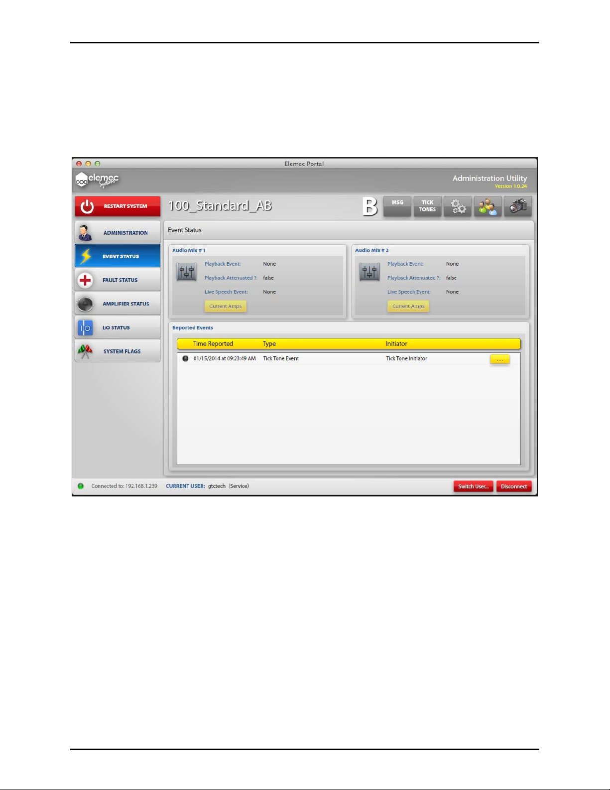
Event S tatus Button
Click the EVENT STATUS button on the Administration Utility screen to display the Event Status screen
as shown in Figure 41. The button turns blue to indicate which screen is currently being displayed.
This screen displays the active Events in the system. Events are defined during the system configuration
process.
Figure 41. Event Status screen
Audio Mix #1, Audio Mix #2
The system has two audio paths: Audio Mix 1 and Audio Mix 2. When an Audio Mix is in use, the
description of the active event(s) is shown.
Playback Event – If present, displays the description of the Playback Event as defined in the system
configuration.
Playback Attenuated? – When True, playback audio for this Audio Mix is attenuated.
Live Speech Event – If present, displays the description of the Live Speech Event as defined in the
system configuration.
Current Amps – Click the C
URRENT AMPS button to display which amplifiers are receiving audio from
this Audio Mix.
f:\standard ioms - current release\ 42004 instr. manuals\42004-485a.docx
02/14
Page 29

Pub. 42004-485A
Elemec3 Portal User Manual Version 1.2 Page 27 of 35
Reported Events
Reported Events section lists active events in the system. Clicking the Details button (shown as “…”) for
a specific event displays the Event Details screen associated with that event with the available
information. An example showing a Tick Tone Event is shown in Figure 42.
Figure 42. Event Details screen (example of a Tick Tone Event)
Description – is the description of the Event Type as entered in the Elemec3 Console configuration.
Initiator – is the description of what triggered the Event.
Routing Status – indicates whether the audio is fully routed, partially routed, or not routed at all due to
audio resource allocation.
Acknowledged Status – indicated whether the event has been acknowledged.
Zones Targeted – lists the intended zones for the event regardless of audio resource availability.
Outputs Targeted – lists the configured output activations for the event. Zone aware outputs listed may
not be active.
f:\standard ioms - current release\ 42004 instr. manuals\42004-485a.docx
02/14
Page 30

Pub. 42004-485A
Elemec3 Portal User Manual Version 1.2 Page 28 of 35
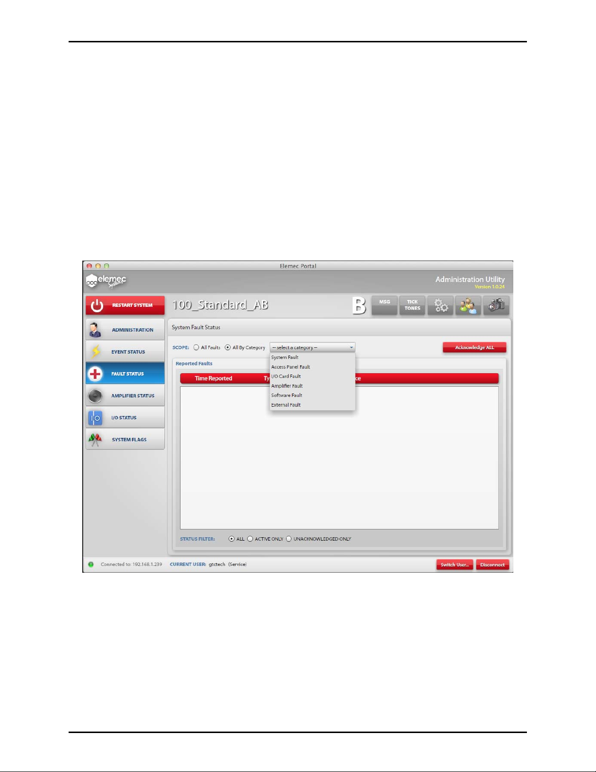
Fault Status Button
Click the FAULT STATUS button to display the System Fault Status screen as shown in Figure 43. The
button turns blue to indicate which screen is currently being displayed.
Figure 43. System Fault Status screen
Two types of faults will be reported: Normal and Urgent.
Urgent faults require acknowledgement. They will remain in the list until the fault is cleared and
acknowledged.
Normal faults do not require user acknowledgement and will be removed from the list when the fault
is cleared.
Fault Notification Panel
The Fault Notification Panel is located on the lower left side of the Administration Utility screen and is
shown in Figure 43 above. The panel will appear when a fault occurs and will display the most recent
unacknowledged fault on any system screen. It contains an A
CKNOWLEDGE FAULT button.
f:\standard ioms - current release\ 42004 instr. manuals\42004-485a.docx
02/14
Page 31
Pub. 42004-485A
Elemec3 Portal User Manual Version 1.2 Page 29 of 35
System Status LED Indicator on E3 Controller
The System Status LED indicator on the E3 Controller has four states indicating fault status.
Green – indicates there are no active faults in the system.
Orange – indicates there are active Normal faults and no active Urgent faults.
Flashing Red – indicates all active Urgent faults have been acknowledged.
Red – indicates there are unacknowledged Urgent faults in the system.
Scope
All Faults – selects all System Faults.
All By Category – when selected, presents a drop down box as shown in Figure 44 that allows the user to
filter the events by category.
Acknowledge All – Click the A
CKNOWLEDGE ALL button to acknowledge all the faults being displayed.
Figure 44. System Fault Status screen showing Scope Category Filter drop down box
Status Filter
In addition to the Scope filter, faults can be filtered by the Status Filter:
All – displays all Faults (active, acknowledged and unacknowledged) in the system.
Active Only – are Faults that have not been cleared from the system.
Unacknowledged Only – are active Faults that have not yet been acknowledged.
f:\standard ioms - current release\ 42004 instr. manuals\42004-485a.docx
02/14
Page 32

Pub. 42004-485A
Elemec3 Portal User Manual Version 1.2 Page 30 of 35
Fault Reporting Configuration in Elemec3
Shown below are the different Fault Categories and types as defined in the Elem ec3 Console
application:
System Fault
Access Panel Fault
I/O Card Fault
Amplifier Fault
Software Fault
External Fault
The Fault Reporting Configuration screen shown in Figure 45 is from the Elemec3 Console and displays
the possible Fault Categories: N
OTE: This screen is not available through the Elemec3 Portal
application.
Figure 45. Fault Reporting Configuration screen (from Elemec3 Console software)
f:\standard ioms - current release\ 42004 instr. manuals\42004-485a.docx
02/14
Page 33

Pub. 42004-485A
Elemec3 Portal User Manual Version 1.2 Page 31 of 35
Amplifier Status Button
Click the AMPLIFIER STATUS button to display the System Amplifier Status screen as shown in Figure
46. The button turns blue to indicate which screen is currently being displayed.
Figure 46. System Amplifier Status screen
Scope
Displays the amplifiers currently controlled by the local system.
LOCAL Amplifiers Only
LOCAL and REMOTE Amplifiers – In an A/B system, local system is controlling all amplifiers.
NONE (Remote System Control) – In an A/B system, remote system is controlling all amplifiers.
Activate Amp Switchover – Click A
amplifiers to the remote sys tem . When the local system is in control of all amplifiers, the A
CTIVATE AMP SWITCHOVER button to transfer control of local
CTIVATE AMP
SWITCHOVER button is disabled.
Deactivate Amp Switchover – Click D
EACTIVATE AMP SWITCHOVER to return control of local
amplifiers to the local syste m.
f:\standard ioms - current release\ 42004 instr. manuals\42004-485a.docx
02/14
Page 34

Pub. 42004-485A
Elemec3 Portal User Manual Version 1.2 Page 32 of 35
Amplifier Status List
The Amplifier Status list displays each amplifier and its current operating condition. Remote amplifiers
will be designated by the [R] prefix.
Fault statu s – indicates Normal or Faulted status.
Audio Status:
OFF – indicates amplifier is idle.
MIX 1/MIX 2 – indicates amplifier active audio source.
HOT STANDBY – indicates designation as a Hot Standby Amplifier.
Standby – if the amplifier channel is faulted, the configured Hot Standby amplifier description is
displayed.
Standby FOR – If a Hot Standby amplifier is currently in use, the description of the faulted amplifier
channel is displayed.
Status Filter
All – Displays all amplifiers.
Active/Faulted – Amplifiers can be filtered to display active/faulted only.
f:\standard ioms - current release\ 42004 instr. manuals\42004-485a.docx
02/14
Page 35

Pub. 42004-485A
Elemec3 Portal User Manual Version 1.2 Page 33 of 35
I/O Status Button
Click I/O STATUS button to display the System I/O Status screen as shown in Figure 47. The button turns
blue to indicate the screen currently being displayed.
Figure 47. System I/O Status screen
f:\standard ioms - current release\ 42004 instr. manuals\42004-485a.docx
02/14
Page 36

Pub. 42004-485A
Elemec3 Portal User Manual Version 1.2 Page 34 of 35
Scope
To filter the displayed I/O points, select I/O Controller.
Link Status Filters – When checked, the Status Filter selection applies to both the Inputs and Outputs
panels.
Figure 48. System I/O Status screen (showing the I/O Controller selection drop down box)
Input Status/Output Status
System Input and Output Status panels display each I/O point in the selected scope and its current state:
ACTIVE
IDLE
FAULTED
INHIBITED
Status Filter
A Status Filter is available on both the Input and Output Status panels.
All – shows all Inputs/Outputs
Active/Faulted Only – Either panel can be filtered to show only the input or output points that are
active/faulted.
f:\standard ioms - current release\ 42004 instr. manuals\42004-485a.docx
02/14
Page 37

Pub. 42004-485A
Elemec3 Portal User Manual Version 1.2 Page 35 of 35
System Flags Button
Click the SYSTEM FLAGS button to display the Logic Flag Status screen as shown in Figure 49. The
button turns blue to indicate which screen is currently being displayed.
Figure 49. Logic Flag Status screen
Scope
Link Status Filters – When checked, the Status Filter selection applies to both the System Flag and User
Flag panels.
System Flag Status / User Flag Status
The Flag Status panels display each logic flag in the system and its current status: ACTIVE or IDLE.
Active flags are noted with a green indicator.
Status Filter
All – All system flags are displayed.
Active – Flags are filtered to display Active flags only.
f:\standard ioms - current release\ 42004 instr. manuals\42004-485a.docx
02/14
 Loading...