

1
BS 260/261-6..
en
fr
Installation Instructions
please keep
Notice de montage
à garder soigneusement
Instrucciones de Montaje
por favor, guardar
es
1
min. 8"
(min.200)
7/16"
(10)
1/4"
(5)
17
(450)
3/4"
28 1/2"
(724)
min. 21 11/16"
(min. 550)
21 1/16"
(535)
1 7/8"
(47)
17 15/16"
(455)
29 5/8"
(752)
! Important Safety Instructions
READ AND SAVE THESE INSTRUCTIONS
WARNING: If the information in this manual is not
followed exactly, fire or shock may result causing
property damage or personal injury.
WARNING: Do not repair or replace any part of the
appliance unless specifically recommended in the
manuals. Improper installation, service or
maintenance can cause injury or property damage.
Refer to this manual for guidance. All other
servicing should be done by a qualified technician.
! Appliance Handling Safety
Do not lift appliance by door handle. Remove the
door for easier handling and installation. See
instructions in Use and Care Manual.
Unit is heavy and requires at least two people or
proper equipment to move.
Hidden surfaces may have sharp edges. Use
caution when reaching behind or under appliance.
Safety Codes and Standards
This appliance complies with one or more of the
following Standards:
UL 858, The Standard for the Safety of Household
Electric Ranges
UL 923, The Standard for the Safety of Microwave
Cooking Appliances
UL 507, The Standard for the Safety of Electric
Fans
ANSI Z21.1-2000, The American National Standard
for Household Cooking Gas Appliances
CAN/CSA-C22.2 No. 113-M1984 Fans and
Ventilators
CAN/CSA-C22.2 No. 61-M89 Household Cooking
Ranges
It is the responsibility of the owner and the installer
to determine if additional requirements and/or
standards apply to specific installations.
2
en
3
11/16"
(94)
2
min. 1/4"
(min. 5)
min.90°
3

3
! Electric Safety
Before you plug in an electrical cord, be sure all
controls are in the OFF position.
If required by the National Electrical Code (or
Canadian Electrical Code), this appliance must be
installed on a separate branch circuit.
Installer - Show the owner the location of the circuit
breaker or fuse. Mark it for easy reference.
Important - Save these instructions for the local
electrical inspector's use.
Before installing, turn power OFF at the service
panel. Lock service panel to prevent power from
being turned ON accidentally.
Refer to data plate for more information.
Be sure your appliance is properly installed and
grounded by a qualified technician. Installation,
electrical connections and grounding must comply
with all applicable codes.
! Related Equipment Safety
Remove all tape and packaging before using the
appliance. Destroy the packaging after unpacking
the appliance. Never allow children to play with
packaging material.
Never modify or alter the construction of the
appliance. For example, do not remove leveling legs,
panels, wire covers or anti-tip brackets/screws.
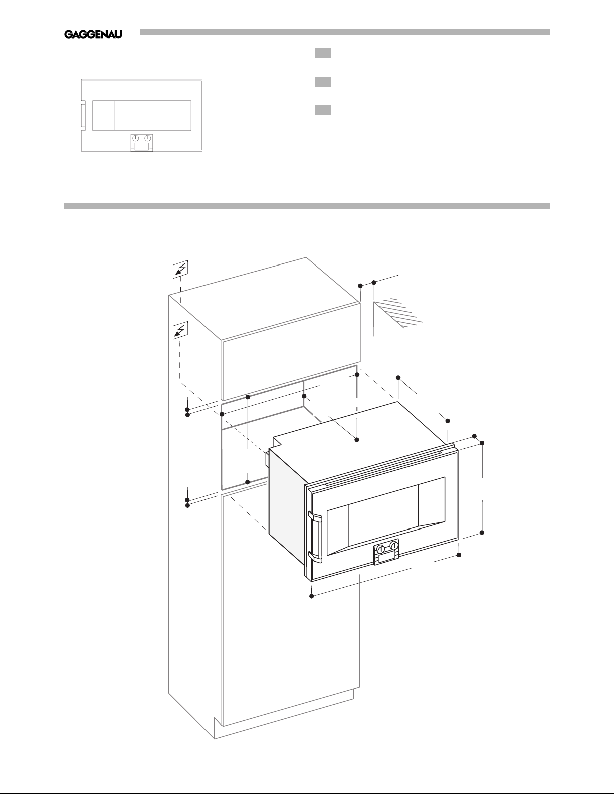
Preparing the Cabinet – Figure 1
Fitted units must be heat-resistant up to 200°F,
adjacent unit fronts up to at least 160°F.
Secure furniture which is not fitted to the wall using
a standard fixture.
Install the appliance low enough to allow trays to be
easily removed.
Electrical Connection
Observe rating plate data for voltage and total
rating.
Attach flexible conduit to the junction box.
Connect the oven lead wires to the junction box
supply wires in proper phase. Only connect in
accordance with the connection diagram.
1. Connect the red oven wire to the red electrical
supply wire (hot wire).
2. Connect the black oven wire to the black
electrical supply wire (hot wire).
3. Connect the bare ground oven wire to the bare
ground electrical supply wire.
To facilitate service, the flex conduit must not be
shortened and should be routed to permit temporary
removal of the oven.
NOTE: If the oven is installed and connected as
specified above, it will be completely grounded in
compliance with the National Electrical Code.
Do not trap the lead during installation and do not
guide it over sharp edges.
An all pin isolating switch with a contact gap of at
least 3 mm must be installed.
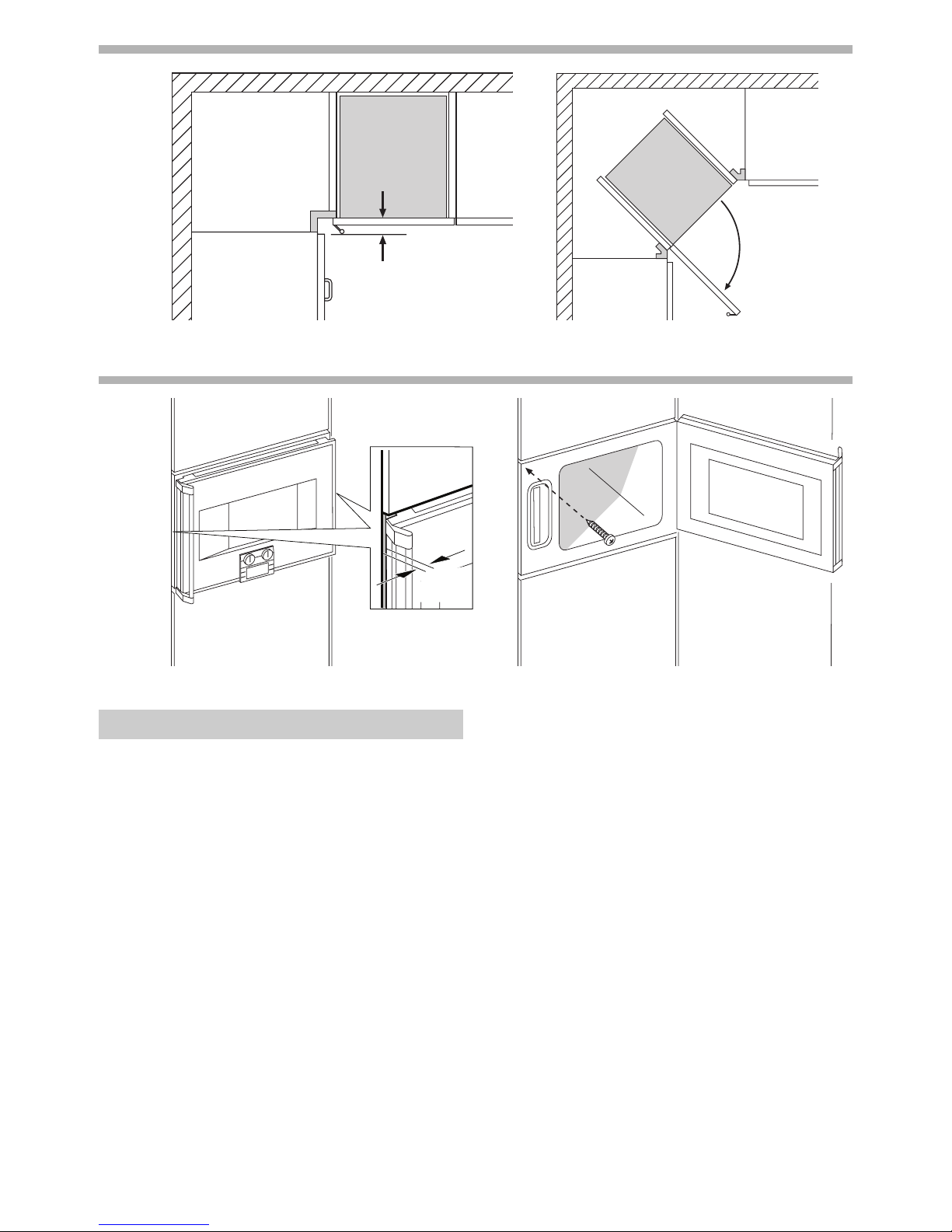
Corner Installation – Figure 2
Observe space requirements of door and door
handle when planning drawers beside the appliance:
measurement cabinet edge – door panel:
1 7/8 ˝ (47 mm)
measurement cabinet edge – door handle edge:
3 11/16 ˝ (94 mm)
Observe a minimum opening angle of 90° for corner
installation.
Installation – Figure 3
Important: When handling the appliance do not
reach into the air flap on top of the oven interior. Do
not lift the appliance by the door or the door handle.
Important: The model that features the controls at
the bottom should not be placed directly on the
floor. Place some wooden strips under it. Do not tilt
the appliance towards the front, this might damage
the controls.
Insert the appliance in the cabinet. Align the
appliance centrally and horizontally.
Use a spirit level to check that the appliance is
installed exactly horizontally. Level installation is
important for the functioning of the appliance.
Leave an air gap of at least
1
/4 ˝ (5 mm) between the
appliance and the front of other cabinets.
Secure the appliance with the screws provided.
Do not seal the ventilation openings of the appliance
with additional strips.
Do not install the model that features the controls at
the bottom above a dishwasher. Steam from the
dishwasher might damage the electronics of the
steam oven.
Combination with Oven BO 2..
Fit the steam oven first, then the oven.
When installing the appliances side-by-side, the
door handles must be in the centre.
 Loading...