

Page 1
1M23N14302
MOUNTING PRECAUTIONS
Before using your MC800C Ver.2, please read
this manual thoroughly and use the MC800C
MC800C Ver.2
NSTRUCTION
I
MANUAL
Ve r.2 properly and safely. After reading this
manual, store it in a safe place.
• No part of this manual may be reproduced in any form
without prior permission.
• The contents of this manual are subject to change without
prior notice.
• This manual has been carefully written. Please write to
Futaba if you feel that any corrections or clarifications
should be made.
Thank you for purchasing an MC800C Ver.2. The MC800C Ver.2 is a high-frequency drive
FET speed control developed for model electric cars. It is compact and light weight
competition speed control, and uses a simple digital setting system.
Applicable motors (Number of turns is criteria.)
Use the MC800C Ver.2 with a motor with 5 turns or
more.
*If a motor with a number of turns smaller than the above
is used, the heat protector and overcurrent protection
circuit may operate. The number of turns of the motor is
a criteria only. Depending on the running conditions, the
protection circuit may operate even if the condition
above is satisfied.
Power supply
Nicd, NiMH battery 4~7 cells
(4.8~8.4V)
DESCRIPTION OF FEATURES
• SMD MOSFETs with smallest internal resistance for minimal losses and
maximum power
• Digital variable modes “Power Control 2”, “Hyper Brake” and “Neutral Brake”
MC800C Ver.2 features three different modes which enable you to adjust motor power and
the driving “feel” to match your special requirements precisely.
Power Control 2 is a revolutionary digital motor management system, which enables you to
set the rate of acceleration to meet your specific preference. This system replaces simple
technologies such as current limiting and variable frequencies.
Hyper brake allows you to set a certain level of “hand-brake effect” in an emergency, i.e. you
can vary the minimum brake effect when you apply the brake.
Neutral brake allows you to set a slight braking action which is applied in the neutral range.
This enables you to hold the throttle on longer when entering a turn. Your car also has greater
front axle grip with this setting.
• External solder points with 12 AWG silicone flex wire
• Start Acceleration function
The start of a race is often crucial to the result. You can exploit the Start Acceleration system
to give you the crucial advantage at start time, as the system shortens the speed control’s
response time at this critical moment, with the result that you have more acceleration
available.
• 4-cell operation possible without receiver battery
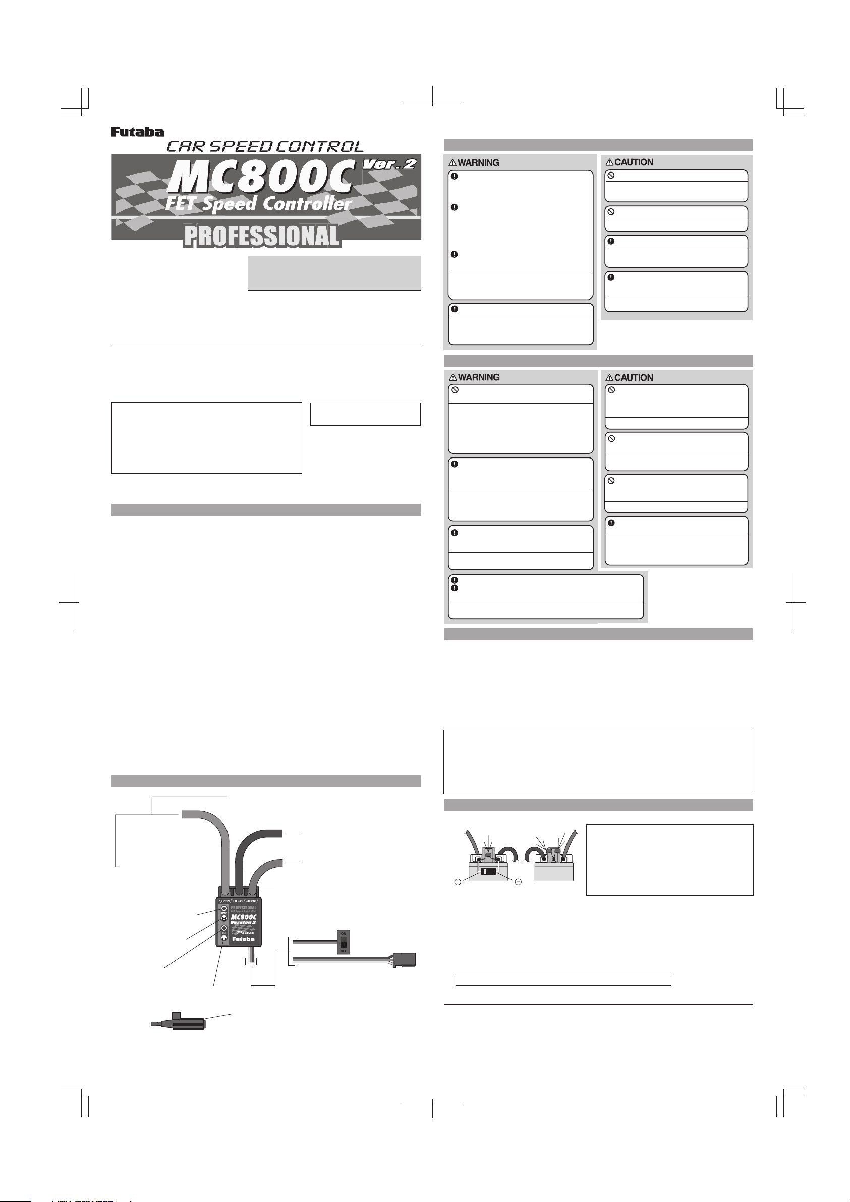
CONNECTION
Red-positive (+B) battery
Black-negative (-B) battery
Red-positive (+M) motor
MODE
Pushbutton
switch
MODE LED
SET
Pushbutton
switch
SET LED
MC800C Ver.2
Accessories:
• Miniature screwdriver
(Use to press the pushbutton switch.)
• Schottky diode (for motor)
• Capacitors (for motor)
• Double sided tape
• Others
Blue-negative (-M) motor
Terminal cover
Power switch
Receiver connector
Connects to the receiver throttle
channel.
Install the receiver and receiver antenna
away from the amp, motor cord, power
cord, Nicd battery, and other parts that
carry a high current.
Metal and carbon chassis and other
conductive parts transfer switching
noise. When mounting the receiver to
such a chassis, use thick double-sided
tape to mount the receiver as far away
from the chassis as possible.
Always install a motor noise suppresser
capacitor. Also, do not forget to service
the brushes, and other parts.
If noise causes the receiver to operate
erroneously, control may be lost and an
extremely dangerous situation may occur.
Insert the connectors firmly.
If vibrations while running cause the
connectors to work loose, control may be lost
and an extremely dangerous situation may
occur.
Do not wrap your MC800C Ver.2 in foil.
It is important to provide a free flow of
cooling air over it.
Do not remove the case of MC800C Ver.2.
The MC800C Ver.2 may not be repairable.
Never reverse the battery polarity.
Reverse connection will immediately destroy
the amp.
Mount the MC800C Ver.2 so that conductive
parts do not directly touch the solder parts
of the input/output cord.
A short circuit may occur.
OPERATING PRECAUTIONS
Do not run the vehicle in the rain or through
puddles or on muddy or snowy roads.
If moisture enters the amp, erroneous
operation may cause loss of control and an
extremely dangerous situation may occur. It
may also cause amp trouble. Should
moisture enter and cause erroneous
operation, send the MC800C Ver.2 out for
repair and inspection.
Always turn the power switches on and
off in the following order:
ON: Transmitter -> receiver (amp switch)
OFF: Receiver (amp switch) -> transmitter
If the power switches are operated in the
opposite order, the vehicle may run
unexpectedly and an extremely dangerous
situation may occur.
When going to and returning from the
circuit, and when storing the model,
always remove the Nicd battery.
If the switch is turned on erroneously, control
may be lost or a fire may start.
Always perform a check of operation before running.
When making adjustments, remove the motor, or place
the vehicle on a stand, so that it cannot run.
When not set up correctly, the vehicle may run unexpectedly
and an extremely dangerous situation may occur.
If a peddle or other foreign object gets
caught in the gears or the vehicle hits
an obstruction, do not try to forcefully
run vehicle.
Forcefully running the vehicle will cause trouble.
Do not touch the motor or MC800C
Ver .2 immediately after running.
Touching the motor or amp immediately after
running may result in serious burns.
If the motor is connected to the speed
control, you must not run the motor by
connecting a separate battery.
This will wreck the unit.
Tu rn the power switches on in the state
where the vehicle is floated.
When turnning on, depending on the
receiver used, a motor may rotate for a
moment. Be careful not to injure a finger etc.
by rotation of the wheels.
INSTALLATION TIPS
•Mount the speed control in the model using the double-sided foam tape supplied.
•Provide plenty of cooling openings in the bodywork; this increases the performance and
extends the life of all electronic components.
•Install the speed control in a location where it is protected from crash damage.
•The speed control should be installed in such a way that you have easy access to all
connectors and the set-up button.
•For extreme applications, use a special heat-sink sold separately. Note: not strictly essential.
Naturally, MC800C Ver.2 also works perfectly without the heat-sink.
Important:
•Ensure that there is an adequate distance (approx. 3 cm) between the speed control and
power cables and the receiver or receiver antenna. Avoid direct contact between all power
system components and the receiver or antenna, as this can cause interference. If you
encounter interference problems, re-position the components in the model.
•The antenna should be run vertically up and away from the receiver. Avoid contact with any
parts made of carbon fibre or metal. See also the instructions supplied with your radio
control system.
INSTALLATION
•Solder the suppressor capacitors and the Schottky diode to the motor.
1
2
Schottky diode
•Remove the motor pinion, or ensure in some other way that the wheels of the model
can rotate freely.
•Install the MC800C Ver.2 in the model.
•Connect the MC800C Ver.2 to the receiver (throttle channel).
•Connect the MC800C Ver.2 to the motor: red wire to positive (+), blue wire to
negative (-).
•Check all the wiring and connections before you connect the MC800C Ver.2 to a
drive battery.
Caution: incorrect polarity will wreck your MC800C Ver.2.
The MC800C Ver.2 is now ready to be set-up (see back page).
[MC800C Ver.2 Technical Data]
• Operating system: Forward and brake
• Power requirement: Nicd, NiMH battery 4~7 cells
(4.8~8.4V)
• PWM frequency: 3.1kHz (Especially Power
Control level 4 is performed by load adaptive.)
• Setting: One-touch input by pushbutton switch.
• Current capacity (Momentary load): 235A (FET
rating)
Motors with no suppressor capacitors, or
3
inadequate suppression, may cause the
MC800C Ver.2 to malfunction. Always solder the
capacitors supplied to your motor.
The schottky diode improves the efficiency of
the speed control / motor combination and
provides extra protection to the brake FETs. The
white ring must always face the positive side.
(Specifications are subject to change without prior notice.)
• Case size: 28.3x25.4x14.4mm
(excluding protruding parts)
• Silicon cord gauge size: AWG12 equivalent
• Weight: 17.5g
(excluding connector, cords and switch)
• BEC voltage: 5.8V
(excluding at 4 cells)
Page 2
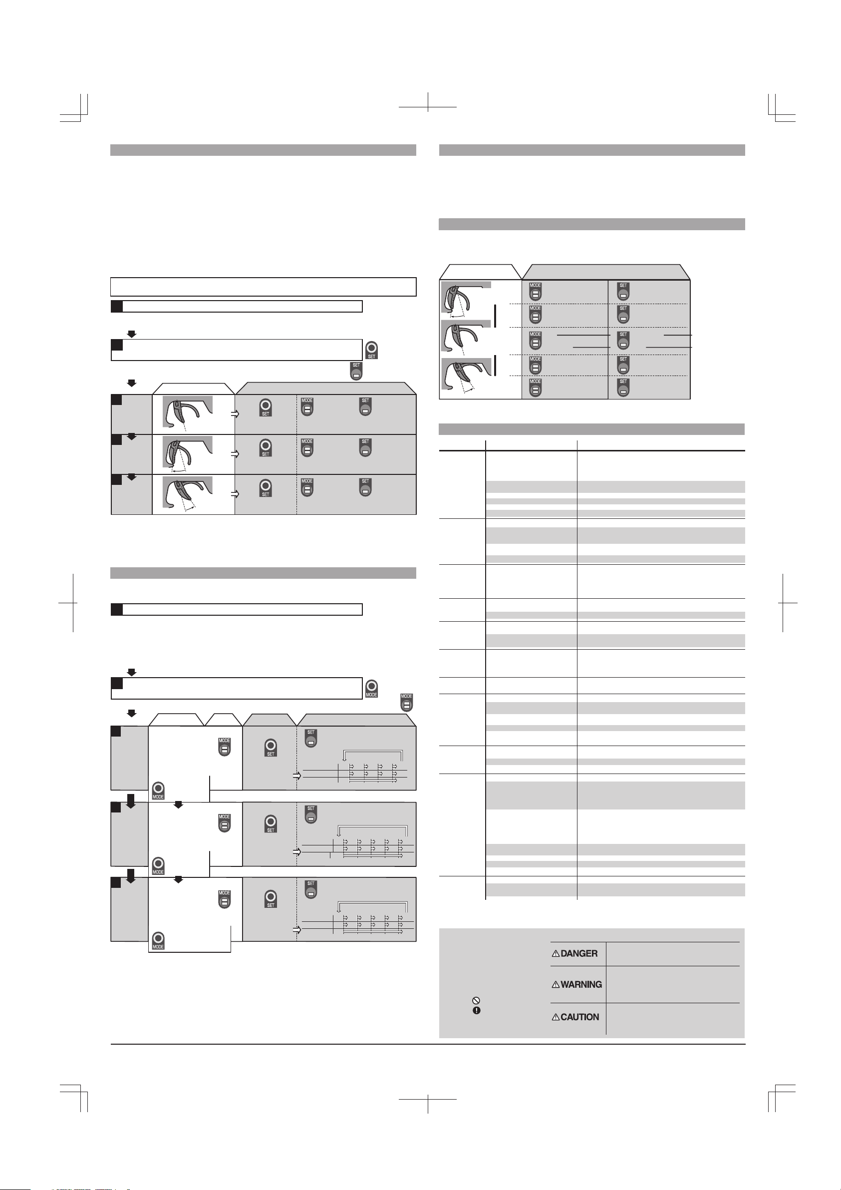
SET UP
Neutral, high, and brake MAX points setting
In set-up mode MC800C Ver.2 stores every step when you press the Set-up button. All the
settings are stored in the unit even when the speed control is subsequently disconnected from
the battery. Set up the following basic functions on your transmitter (if present):
• High ATV, EPA (throttle travel) - maximum
• Low ATV, EPA, ATL (brake travel) - maximum
• EXP, EXPO (exponential) - start with 0
• SUB trim (neutral trim) - center
• TH trim - center
• Throttle reverse (servo reverse) - any setting; must not be changed after completion of
set-up procedure.
• Asymmetrical stick travel is possible (2/3 throttle - 1/3 brake)
If your transmitter does not feature these set-up functions, it is already in “basic set-up” mode.
Remove the motor pinion, or ensure in some other way that the wheels of the model are free
to rotate.
Tu rn on the power in following order.
1
• Switch the transmitter on.
• Set the transmitter throttle stick to neutral, and then switch the speed control on.
Hold the SET button pressed in for at least 3 seconds using the
2
small screwdriver supplied.
• The SET LED flashes red, to indicate that the unit is in set-up mode.
It continues flashing until the set-up procedure is completed.
MC800C Ver.2
・MODE LED
flashes green
and the motor
beeps.
・MODE LED
flashes red.
・MODE LED
glows red.
・SET LED
flashes red.
・SET LED
flashes red.
・SET LED
glows red.
3
Neutral
point
setting
4
High
point
setting
5
Brake MAX
point
setting
Transmitter throttle operation
・Neutral state
N
N
・Full high state
・Full brake state
N
SET button operation MODE LED SET LED
・Press SET button
once.
・Press SET button
once.
・Press SET button
once.
• This completes the set-up procedure. Check the operation by the following "CHECKER
LED DISPLAY." When throttle operation and the CHECKER LED DISPLAY are not
correct, set up again from the first step.
• If you make a mistake during the set-up procedure, don't worry: switch MC800C off for
about 10 seconds and start again from the first step.
DIGITAL VARIABLE MODES SETTING
Power Control 2, Hyper Brake, and Neutral Brake settings
You can change the Mode settings as described below.
Tu rn on the power in following order.
1
• Switch the transmitter on.
• At race events you usually do not have access to your transmitter. In this situation it is
possible to adjust the speed control’s settings without the transmitter signal. All you have to
do is disconnect the receiver lead (attached to the speed control) from the receiver. (In this
case, remove the motor pinion, or disconnect the motor.)
• Switch the speed control on.
Hold the MODE button pressed in for at least 3 seconds using the
2
small screwdriver supplied.
• The Mode LED flashes green to indicate that you have selected ‘Power Control’ mode.
MODE button
operation
3
Power
Control 2
mode
setting
4
Hyper
Brake
mode
setting
5
Neutral
Brake
mode
setting
Power Control 2 set value:
1: for low grip
2: for off-road
3: for touring car
4: load adaptive mode
5: for stock racing
(*1)According to the setting of Neutral
Brake, the range of Hyper Brake which
can be set up changes. For example,
when Neutral Brake is set as the level
2, the setting range of Hyper Brake
serves as levels 2-5.
•The MODE LED flashes
green to indicate that you
have selected ‘Power
Control’ mode.
•Press the Mode
button again to
move to the
next mode.
•The MODE LED flashes
red to indicate that you
have selected ‘Hyper
Brake’ mode.
•Press the Mode
button again to
move to the
next mode.
•The MODE LED flashes
red/green to indicate that
you have selected ‘Neutral
Brake’ mode.
•Press the MODE button
again to complete the
programming procedure
and return to the normal
mode of operation.
MODE
LED
FUTABA CORPORATION Makuhari Techno Garden Bldg., B6F 1-3 Nakase, Mihama-ku, Chiba 261-8555, Japan Phone: (043) 296-5118 Facsimile: (043) 296-5124
SET button
operation
•You can adjust the
value by pressing
the SET button.
•Press the SET
button to change
the value.
(*1)
•Press the SET
button to change
the value.
Default settings:
MC800C Ver.2 speed controls are supplied factory-adjusted.
The default setting is this:
•Power Control 2 = 2
•Hyper Brake = 2
•Neutral Brake = 0
If you lose track of the modes during the set-up procedure, you
can reset the speed control to the default settings. With the
transmitter switched on, hold the SET button pressed in while
you switch on the speed control. This action returns the unit to
the factory settings.
Flash number
Set value
Powe r level
Flash number
Set value
Brake
Flash number
Set value
Brake
SET LED
•You can check the set value (1-5) by
counting the flashes of the red SET
LED (one flash equals value 1, two
flashes value 2 etc.)
12 3 4 5
12 3 4 5
Min
(Smooth) (Mega punch)
•The SET LED now shows the stored
value again.
1002345
1234 5
Linear
•The SET LED shows the stored value
again.
1002345
1234 5
Max
Max
(Progressive)
MaxOff
(Strong)
START ACCELERATION FUNCTION
Start Acceleration function setting
• Activate Start Acceleration by holding transmitter at full brake for 5 sec before start.
This system shortens the speed control’s response time at start time, with the result that you
have more acceleration available.
CHECKER LED DISPLAY
Relationship between amp operation and checker LED display
The MC800C Ver.2 operating state can be checked with the checker LED as shown below.
Operation
High
point
Neutral
point
Brake MAX
point
Forward
Brake
Checker LED display
On (green) On (red)
On (green)
*Becomes brighter nearer
the high point.
Off
On (red)
On (red)
*Becomes brighter nearer
the MAX point.
On (red)
Off
On (red)
Off
Off
On (red)
at Normal Brake
at Neutral Brake
TROUBLE-SHOOTING GUIDE
Symptom
Steering servo
works,
but no motor
function.
No steering
servo function or
motor function
Motor does not
run when throttle
is advanced;
motor runs when
braking
No brake
function
Poor braking
effect
Insufficient top
speed
Poor
acceleration
Speed control
overheats
Motor does not
stop; continues
running slowly.
Radio
interference
Imprecise, nonlinear control
characteristics
Set-up/basic settings problem
Speed control connected to wrong
receiver channel
Motor defective
Motor brushes stuck
Wiring problem
Speed control defective
Receiver plug incorrectly wired
Crystal faulty
Receiver faulty
Transmitter faulty
Speed control damp, protective
circuit tripped
Receiver power supply circuit faulty
Transmitter throttle polar ity
(direction) has been changed
Set-up/basic settings problem
Speed control faulty
Set-up/basic settings problem
Motor pinion/reduction ratio too
large
Problem with set-up/basic settings
Transmitter has been changed
after speed control set-up, or has
changed its own settings.
Motor faulty, brushes sticking
Inadequate cooling
Motor too powerful, or input voltage
too high
Motor pinion/reduction ratio too
large
Car drive/bearing system problem
Motor run too often without cooling
period.
Damp in speed control
Set-up/basic settings problem
Speed control faulty
Motor inadequately suppressed
Receiver or antenna too close to
power cables, motor, battery or
speed control;
Receiver antenna too short, or
coiled up.
Receiver fault
Transmitter or transmitter module
fault
Servo fault
Crystal fault, or crystal not correct
type
Powe r cables too long, red power
cable connected incorrectly.
Connector contact problem.
Transmitter batter y/cells flat
Transmitter antenna too shor t
Transmitter batter y/cells flat
Transmitter or transmitter "car
program" has been changed.
Special Markings
Pay special attention to the
safety at the parts of this
manual that are indicated by
the following marks.
Symbol: ; Prohibited
; Mandatory
Cause
Remedy
Repeat basic speed control set-up procedure from start; to store
the function correctly you must hold stick in full-throttle position
while you press the set-up button.
Note also that all transmitter functions must be set as described
in the instructions.
Speed control must be connected to Ch.2; check polarity of
receiver lead.
Fit new motor.
Check that carbon brushes are free to move.
Check cables and connectors.
Send unit in for repair.
Check polarity of receiver plug.
Replace components one by one to locate fault.
Switch off immediately, allow speed control to dry out.
Check BEC output voltage, or send unit in for repair.
Simply repeat speed control set-up procedure
Leave transmitter stick direction unchanged
Repeat basic speed control set-up procedure from start;
see also "Motor does not run" point.
Send unit in for repair.
Repeat basic speed control set-up (see above), or reset Low ATV,
EPA, ATL on transmitter to maximum.
Fit smaller motor pinion.
Repeat basic speed control set-up procedure from start; see also
"Motor does not run" point.
Tr y different motor, free up brushes
Cut cooling openings in bodywork.
Use less powerful motor, or battery with lower voltage/fewer cells.
Fit smaller motor pinion.
Check or replace components.
Allow speed control to cool off after each full run.
Disconnect battery immediately, dry speed control with heat-gun
(hot air).
Repeat basic speed control set-up procedure.
Send unit in for repair.
Solder capacitors to motor.
See "Installation".
Replace components one by one to locate fault.
Use original crystals only.
See "Wiring" and "General installation notes".
Check connectors.
Replace dry cells, recharge NC pack.
Extend transmitter antenna fully.
Check transmitter battery regularly.
Repeat basic speed control set-up procedure.
Mark Meaning
Procedures which may lead to a dangerous
condition and cause death or serious injury to
the user if not carried out properly.
Procedures which may lead to a dangerous
condition or cause death or serious injury to
the user if not carried out properly, or
procedures where the probability of superficial
injury or physical damage is high.
Procedures where the possibility of serious
injury to the user is small, but there is a
danger of injury, or physical damage, if not
carried out properly.
©FUTABA CORPORATION 2004, 5
 Loading...