

Page 1
INSTRUCTION
MANUAL
1M23N08204
Before using your MC330CR, please read this
manual thoroughly and use the MC330CR properly
and safely. After reading this manual, store it in a
safe place.
•No part of this manual may be reproduced in any form without prior
permission.
•The contents of this manual are subject to change without prior
notice.
•This manual has been carefully written. Please write to Futaba if
you feel that any corrections or clarifications should be made.
Thank you for buying an MC330CR. The MC330CR is a high-frequency drive FET amp with reverse
function developed for model electric cars. It is compact and light weight, and uses a simple digital
setting system.
FEATURES
•High-frequency drive system
•Forward, reverse, and brake operations are all
linear
•Reverse operation cancellation function
•One-touch inpu t of neu tral, high, and brake
MAX points by pushbutton switch
•Overcurrent protection function
•Heat protector
•Low-voltage protection function
•Power left on alarm function
•Abnormal input signal cancellation function
•Checker function (LED display, audible beep)
SET UP
Neutral, high, and brake MAX points setting
Before setting each point, set the transmitter throttle channel trim to neutral.
CHECKER LED DISPLAY
Relationship between amp operation and checker LED display
The amp operates linearly in proportion to the amount of forward, reverse, and brake operation. The amp operating
state can be checked with the checker LED as shown below.
BRAKE/REVERSE OPERATING INSTRUCTIONS
Operation can be switched to reverse operation by returning the throttle trigger (or throttle
stick) from the brake position to the neutral position.
PROTECTION CIRCUIT OPERATION
The following protection circuits are built into the MC330CR. When a protection circuit operates, remove the
cause before operating the model again.
Cancelling the reverse function
The amp reverse function can be cancelled by the following method so that the model can be
used even in races that prohibit reverse running. (Brake operation only)
[MC330CR Technical Data]
•Operating system: Forward, reverse, and brake
operations are all linear.
•Power requirement: Nicd battery 6~7 cells (7.2~8.4V)
•PWM frequency: 1.5kHz (fixed)
•Setting: One-touch input by pushbutton switch. Set data
is saved to built-in EEPROM.
•Current capacity (FET rating): Forward=200A,
reverse=100A
Applicable motors (Number of turns is criteria.)
Use the MC330CR with a motor with 13T or
more turns.
*If a motor with a number of turns smaller than the above
is used, the heat protector and overcurrent protection
circuit may operate. The number of turns of the motor is a
criteria only. Depending on the running conditions, the
protection circuit may operate even if the condition above
is satisfied.
Power supply
Nicd battery 6~7 cells (7.2~8.4V)
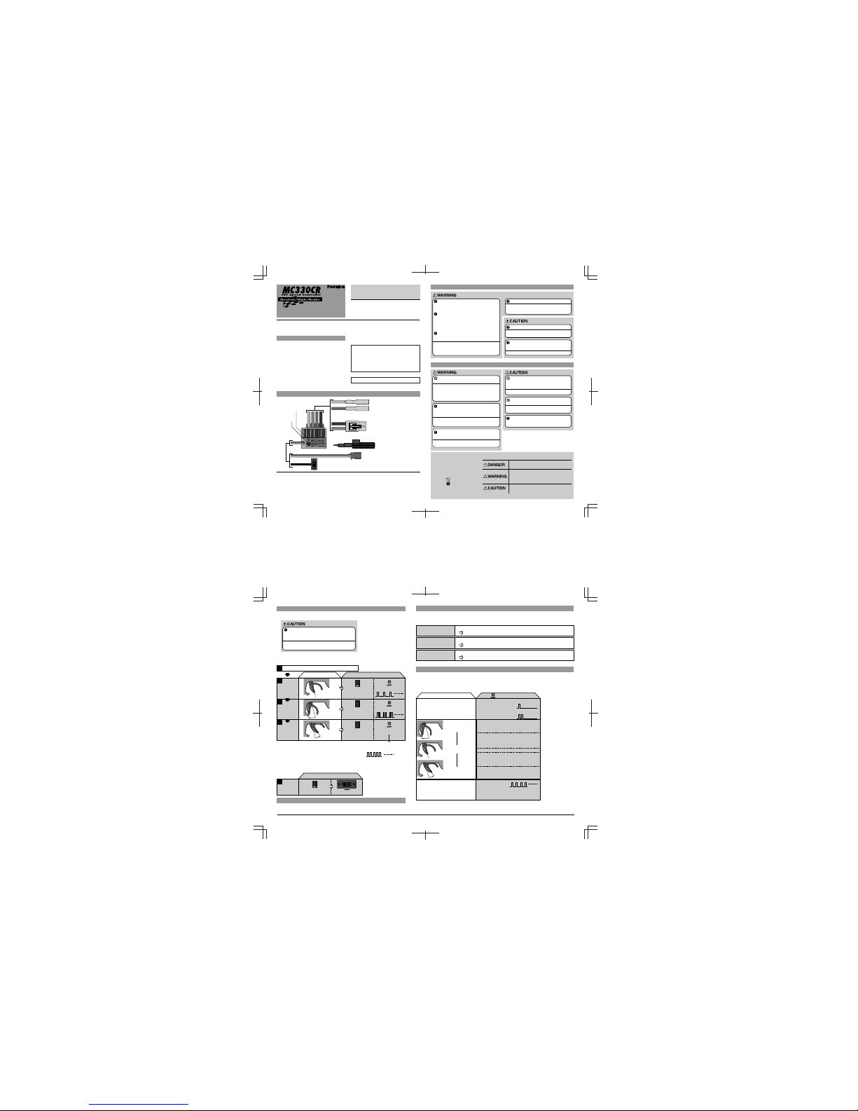
Motor connector
Connects to the motor.
(Orange) is plus. (Blue) is minus.
If the motor rotates in the wrong
direction, interchange the connections of
this connector.
Nicd battery connector
Connects to the running Nicd battery.
(Red) is plus. (Black) is minus.
Receiver connector
Connects to the receiver throttle channel.
Miniature screwdriver
Accessory. Use to press the
pushbutton switch.
(Orange)
(Blue)
(Black)
(Red)
MC330CR
Power switch
Checker LED
Pushbutton
switch
Turn on the power in transmitter -> amp order.
1
2
Transmitter throttle operation
•Neutral state
•Press the pushbutton switch.
(0.5 secs or longer)
(Confirmation beep sounds)
•Continuous single blink
MC330CR
(Pushbutton switch operation) (Checker LED)
N
N
Full High
Full brake
N
Neutral
point setting
Operation
Amp power ON
Checker LED display
(Reverse operation set)
Single blink
(Single confirmation beep)
(Only brake operation set)
Off
On
On
Off
Off
Double blink
(Two confirmation beeps)
Blinks. (Confirmation
beep also sounds.)
While pressing
the pushbutton switch,
set the power switch to ON.
ON
MC330CR
(Pushbutton switch operation) (Power switch)
3
•Full high state
•Press the pushbutton switch.
(Confirmation beep sounds)
•Continuous double blink
•Continuous rapid blink
High point
setting
4
•Full brake state
•Press the pushbutton switch.
(Confirmation beep sounds.)
•If the LED goes out,
setting is complete.
Brake MAX
point setting
1
Reverse
function
cancellation
* Since the data is read at the end of setting of all points, the points
cannot be set independently.
* If the amp power was turned off during setting, the setting points
cannot be memorized. (The previous settings are retained.)
* The confirmation beep sounds only when the motor was
connected.
* Confirmation beep only sounds when the motor was connected.
If the LED does not go off but blinks rapidly, setting
was not performed normally. Repeat setting from
"Neutral point setting".
High point
Neutral point
Brake MAX point
*Becomes brighter nearer the high
point.
*Becomes brighter nearer the
brake MAX point.
*Not used with PCM receivers.
*When the transmitter if OFF, this function is
not performed in environments such that the
servo operates erroneously.
When an overcurrent flows due to an output short circuit, etc., the overcurrent protection circuit automatically
limits the current to protects the FET.
Remove the cause of the short circuit, etc. before operating the model again.
(Amp power left on alarm)
When the transmitter power
was turned off first.
Forward
Reverse
/brake
Overcurrent
protection
When abnormal heating of the FET due to an overload, etc. is detected, the heat protector operates so that
the speed is gradually reduced.
When the FET temperature drops, the heat protector automatically resets. However, remove the cause
of the overheating before operating the model again.
Heat protector
When the Nicd battery voltage drops, this function limits the motor output current and ensures steering operation.
After the speed drops, immediately recover the vehicle.
Low voltage
operation
FUTABA CORPORATION Makuhari Techno Garden Bldg., B6F 1-3 Nakase, Mihama-ku, Chiba 261-8555, Japan Phone: (043) 296-5118 Facsimile: (043) 296-5124
Install the receiver and receiver antenna at
least 1cm away from the amp, motor cord,
power cord, Nicd battery, and other parts that
carry a high current.
Metal and carbon chass is and o ther
conductive parts transfer switching noise.
When moun ting t he rece iver to such a
chassis, use thick double-sided tape to
mount the receiver as far away from the
chassis as possible.
Always install a motor noise killer capacitor.
Also, do not forget to service the brushes,
and other parts.
If noise causes the receiver to operate erroneously,
control may be lost and an extremely dangerous
situation may occur.
Insert the connectors firmly.
If vibrations while running cause the connectors to
work loose, control may be lost and an extremely
dangerous situation may occur.
Never reverse the Nicd battery polarity.
Reverse connection will immediately destroy the
amp.
MOUNTING PRECAUTIONS
OPERATING PRECAUTIONS
Always turn the power switches on and off in
the following order:
ON: Transmitter -> receiver (amp switch)
OFF: Receiver (amp switch) -> transmitter
If the power switches are operated in the opposite
order, the vehicle may run unexpectedly and an
extremely dangerous situation may occur.
If a peddle or other foreig n object g ets
caught in the gears or the vehicle hits an
obstruction, do not try to forcefully run
vehicle.
Forcefully running the vehicle will cause trouble.
Do not touch the motor or amp immediately
after running.
Touching the motor or am p immediatel y after
running may result in serious burns.
When going to and returning from the circuit,
and when storing the model, always remove
the Nicd battery.
If the switch is turned on erroneously, control may
be lost or a fire may start.
When ma king adjustments, remove th e
motor, or place the model on a stand, so
that it cannot run.
(Specifications are subject to change without prior notice.)
Mount the MC33 0CR so that conductive
parts do not directly touch the metal fins of
the FET.
A short circuit may occur.
CONNECTION
•Case size: 27.1x333x12.8mm (excluding protruding parts)
•Silicon cord gauge size: AWG14 equivalent
•Weight: 45g (including connectors and switches)
•BEC voltage: 6.0V
Do not run the vehicle in the rain or through
puddles or on muddy or snowy roads.
If moisture enters t he amp, e rroneous operation
may cause loss of control and an extremel y
dangerous situation may occur. It may also cause
amp trouble. Should mois ture enter and cause
erroneous operation, send the MC330CR out for
repair and inspection.
* When desired, you can enable
the cancelled reverse function by
repeating the operation shown at
the left. (The reverse function is
switched alternately.)
Set the steering angle adjustment function (ATV)
to 100% and the ABS function and acceleration
function to OFF using the trans mitter throttle
channel function.
If t he steering an gle is too la rge or the AB S and
acceleration functions are on, erroneous operation may
occur.
*When using the ABS function,
after setting up the MC330CR, stop
the reverse function, then turn on
the ABS function. If the ABS
function is on, the MC330CR
cannot be set up correctly.
Special Markings
Pay special attention to the safety
at the parts of this manual that are
indicated by the following marks.
Symbol: ; Prohibited
; Mandatory
Mark Meaning
Procedures which may lead to a dangerous
condition and cause death or serious injury to the
user if not carried out properly.
Procedures which may lead to a dangerous
condition or cause death or serious injury to the user
if not carried out properly, or procedures where the
probability of superficial injury or physical damage is
high.
Procedures where the possibility of serious injury to
the user is small, but there is a danger of injury, or
physical damage, if not carried out properly.
©FUTABA CORPORATION 2000, 7
 Loading...