

Page 1
FEATURES OF MAGNUM JUNIOR
The Magnum series are pistol grip type of AM 2 channel digital proportional radio control sets and are the best in their class.
TRANSMITTER FP-T2PKA,
• Newly designed cockpit type control panel
• Human-engineered size and design are easy to use.
•Steering rate adjuster The steering servo travel volume (right 81 left
evenly from neutral) can be adjusted simultaneously, while running.
•Throttle
• Wheel angle adjuster. The turning angle of the steering wheel can
• Neutral adjuster. The throttle trigger throttle stroke/brake deflection
•Servo reversing switch (steering and throttle) is standard Each servo
• Since a level meter is provided, battery consumption can be seen at
• Crystal can be changed from the outside. Crystal can be immediately
• Power supply can be changed to a nicad battery system. FP-T2PKA
RECEIVER
• BEC (Battery Eliminator Circuitry) system allows sharing of the
•
RECEIVER
• High performance AM 4 channel receiver in which miniature size and
• Short (50cm) antenna designed for miniature models is easy to mount.
•
Narrow
• Noise resistance achieved by using a pulse noise rejection circuit.
• New CMOS miniature 1C used in the data coder increases reliability
• New type sub miniature, highly reliable pins used at the crystal socket
• Thick film gold-plated connector pins eliminate poor contact and
ATV
and set with two trimmers, independently. FP-T2PKA
be increased and decreased. This allows operation at the best angle
stroke (back stroke) can be freely selected to match the application
can be reversed from the outside. This is extremely convenient when
connecting the linkages.
a glance.
changed during competitions, etc. except 72 MHz and 75 MHz on
transmitter.
The throttle
FP-R102GR_____________________
running Nicd battery and eliminates the need for a regulator and
diode.
Crystal socket
pins. Reliability is increased and the crystal can be changed from
the outside.
uses a new type
FP-R104H_______________________
light weight have been achieved by using the PC board space to the
maximum.
(27MHz only)
band
channel interference.
substantially.
also increase reliability The crystal can be changed from the outside.
improve reliability against shock and vibration.
design using a narrow band ceramic filter
SERVO FP-S148, S129, S132H
•Motor
uses
the
and smooth operation. (S148, S129)
• These heavy-duty & water/dust tight servos are designed for use with
Futaba digital proportional
• New indirect driver potentiometer improves vibration and shock re-
sistance and increases neutral precision tremendously.
• Futaba low-power custom 1C provides high starting torque, narrow
dead band, and excellent trackability.
• Fiberglass-reinforced PBT (polybutylene terephthalate) injection
molded servo case is mechanically strong and invulnerable against
glow fuel.
• Strong polyacetal resin ultra-precision servo gear features smooth
operation, positive neutral, and very little backlash.
• Fiberglass-reinforced epoxy resin PC board with thru-the-hole plating
improves servo amp vibration and shock resistance.
• Thick film gold-plated connector pins eliminate poor contact and
improve reliability against shock and vibration.
• Special grommet bushing simplifies servo mounting and improves the
cushioning effect.
• Six special adjustable splined horns are available.
• Maximum output torque of 48.7oz-in.(3.0kg-cm/3 5kg-cm) allows
use in almost any model (S148, S129)
• High operating speed of 0.13 sec/60° makes it perfect when especially
high speed is necessary. (S132H)
newest helical type
(FP-T2PK)_____________
servo
travel
volume
of
highly
reliable
rotor
for
improved
radio
control
sets
(S129)
can
be adjusted
subminiature
resists
output
adjacent
torque
SET CONTENTS AND RATINGS
MAGNUM JUNIOR
Transmitter
Receiver
Servo
Others
TRANSMITTER FP-T2PKA.
Operating system : Pistol grip type, 2-channel
Transmitting frequency : 27MHz band 72/75MHz band
Modulation system : AM (amplitude modulation)
Power requirement 12V, AA penlight battery x 8
Receiver
Receiving frequency 75MHz
Intermediate frequency 455kHz
Selectivity :3kHz/-3dB
Receiving range 550 yards (500m) on the ground when
Power supply 4.8V to 8.4V
Current drain 7.2V/13mA, 4.8V/33mA
Dimensions 1.46 x 2.19 x 0.75 in. (37 x 55.5 x 19 mm)
Weight 1.34 oz (38g)
RECEIVER FP-R4H,
Miniature 4 channel AM receiver
Receiving frequency :27MHz band 72/75MHz
Intermediate frequency :455kHz
Power requirement :4.8V to 6.0V
Current drain :10mA
Dimensions :1.26 x 2.05 x 0.77 in. (32 x 52 x 19.4 mm)
Weight :
Receiving range :
SERVO
Control system :+pulse width control
Operating angle : One side 45° or more
Power
Current drain (IDLE)
Output torque :
Operating speed :
Dimensions
Weight : 1.5 oz. (44.4g)
SERVO
Control system :+pulse control
Operating angle :Rotary system, one-side 45" or greater
Power requirement :4.8V to 6.0V (shared with receiver)
Current drain :6.0V, 8mA (at idle)
Output torque
Operating speed
Dimensions :1.79 x 0.9 x 1.71 in. (45.5 x 23
Weight :2.1 oz (60g)
SERVO
Operating system :+pulse control
Operating angle :Rotary system, one-side 40" or greater
Power requirement :4.8V to 6.0V (shared with receiver)
Current drain :6.0V, 8mA (at idle)
Output torque :25.02 oz-in (1.8kg-cm)
Operating speed :0.13 sec/60°
Dimensions :1.46 x 0.71 x 1.20 in. (37 x 18 x 30.5 mm)
Weight :1.13oz(32g)
PP-R102GR
PP-S148__________________________
requirement
FP-S129____________________________
FP-S132H___________________________
FP-T2PKA
FP-R102GR or FP-R104H
FP-S148 x 2 or FP-S129 or
FP-S132H
Switch, battery holder, etc.
(FP-T2PK)_____________
________________________
used with FP-T2PKA (At the best radio
wave condition of environment)
(FP-R104H)_________________
1.06 oz (30g
220
with
condition of environment)
:
4.8V-6V
: 6.0V, 8mA (at idle)
42 oz. in. (3 kg-cm)
0.22 sec/60°
: 1.59 x 0.77 x 1.4in. (40.4 x 19.8
x
(including trim)
:48.7 oz-in (3.5kg-cm)
:0.25 sec /60"
x
43 5 mm)
(including trim)
)
yards(200m) on the ground when used
the
FP-T2PKA(At
36
mm)
FP-T2PK
band
the
best
radio
wave
Page 2
TRANSMITTER FP-T2PKA (FP-T2PK)
HANDLING INSTRUCTIONS
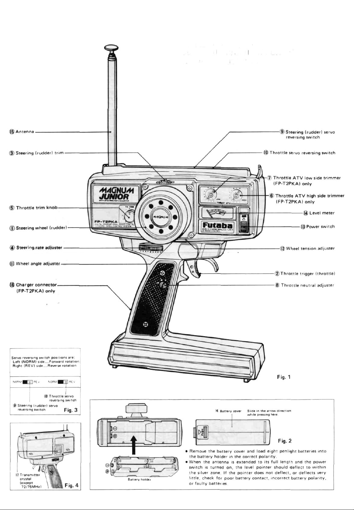
The name of each part of the transmitter
is shown in Fig. 1 and Fig. 2. Learn them
before operating your set.
Page 3
The servo reversing switches are assumed to be in the normal
position in the descriptions in this section. When the servo
switches are in the reverse position, operation is the opposite
of that described here.
(1) Steering wheel (rudder)
Steering (rudder) operation.
(2) Throttle trigger (throttle lever)
Engine control/motor control operation.
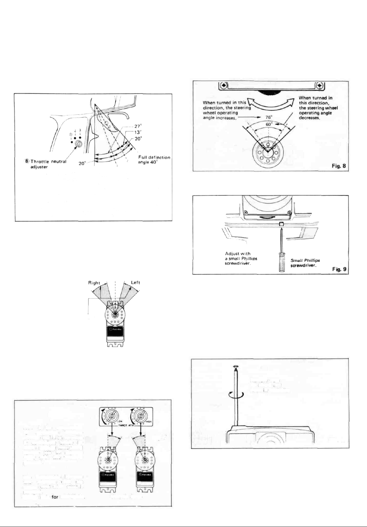
The throttle neutral position can be set to one of three position by
turning
the 8 throttle
Fig. 5. Set it to match the application.
When set to 1 ) the full deflection angle is 40°
When set to 2 ) the throttle throw is 27° and the
brake deflection angle is 13°.
When set to 3 ) the throttle and brake (reverse)
throws are both 20°.
• For engine cars, position 2 is recommended.
• For electric cars, position 3 is recommended when equipped
with reverse mechanism and position 2 is recommended when
equipped with a brake and forward only
neutral adjuster
with a coin
as
shown
Fig.
in
5
(8) Throttle neutral adjuster
This adjuster
throttle trigger. Set it to the point at which it stops with a click
with a screwdriver, coin, etc.
9 Steering (rudder) servo reversing switch
10 Throttle servo reversing switch
(11) Wheel
The wheel angle adjuster changes the operating angle of the (1) Steer-
ing wheel as shown in Fig. 8.
(12) Wheel tension adjuster
This is a phillips head screw which adjusts the steering force of the
steering wheel.
angle
sets
the
adjuster
throttle
trigger
neutral
point
as
described
in
(2)
(3) Steering trim
Steering (rudder) trim
(4) Steering rate adjuster
The steering servo steering angle can be freely set as shown in Fig. 6
with a ratcheted adjuster installed which enables you to adjust steer-
ing servo travel volume to match a car to the course, even while running.
Neutral
The steering angle can be
set within this range.
30%~100%
Steering servo
(5) Throttle trim knob
(6) Throttle ATV high side trimmer ATV... Adjustable Travel Volume.
(7) Throttle ATV low side trimmer
Throttle ATV is a device which permits independent adjustment of
the throttle servo left and right sides (from neutral) as shown in Fig.
7 with trimmers (6) and (7). (FP-T2PKA)
Fig.
(13) Power switch
When set in the direction of the A mark (upper position), the switch
is turned on and the pointer of the level meter deflects.
(14) Level meter
When the 13) power switch is set to ON, the level meter pointer
should deflect to within the silver zone. If the pointer stops near the
boundary between the silver and red zones, the battery is low, and
the range of the radiowaves will be short. When the level meter
pointer drops to the boundary between the silver and red zones,
change the battery.
(15) Antenna
6
95cm antenna. It screws in vertically as shown in Fig. 10.
Remove from
the holder and
screw in vertically.
ATV is the abbreviation
for Adjustable Throttle
Volume and is an extremely convenient device by
which steering servo travel
volume can be adjusted
freely with two trimmers
preloaded.
The relationship between
two trimmers does not
change even when servo is
reversed.
(6)&(7):only
for
FP-T2PKA.
Throttle Servo
Fig.
7
(16) Battery cover
When loading (or changing) the eight penlight batteries, remove this
cover as shown in Fig. 2.
(17) Transmitter crystal
When changing the frequency, replace this crystal. Use the AM crystal set (transmit and receive 1 pair) sold by Futaba. The transmitter
crystal is marked TX and the receiver crystal is marked RX. However,
you are not allowed to change frequency by merely replacing crystal
on both 72 and 75MHz.
Fig. 10
Page 4

The BEC mark is displayed on the front of the receiver of BEC
(Battery Eliminator Circuitry) system sets with a receiver with shared
power supply regulator.
RECEIVER FP-R102GR AND SERVO FP-S148
Fig. 11
(3) When motor car uses an ordi-
nary common power supply
chassis
Red common 2P
connector
(Female pins)
Buy the red common 2P
connector from the kit
manufacturer and connect to
the controller.
Pin 1: Minus
Pin 2. Plus
The Futaba BEC (Battery Eliminator Circuitry) system can also use a common power supply with the conventional four penlight
batteries system (separate power supply).
(2) When motor car uses a speci-
al BEC system chassis (common power supply specifi-
cations)
Red common 2P
connector
Connect to the red common
2P connector of the controller.
Page 5

• A common power supply regulator and diode may also be supplied with the speed controller, depending on the vehicle kit. Since
they cause a voltage drop, always remove them.
• Set the transmitter power switch to ON, then set the receiver power
switch to ON. The servos stop near the neutral position. Operate the
transmitter sticks and check if each servo faithfully follows operation of the sticks.
• Connect the pushrod to each servo horn, then check if the direction of travel of each servo matches the transmitter operation.
• Operate each servo over its full travel and check if the pushrod binds
or
is
too
loose.
adversely affect the servo and quickly drain the battery. Be especially careful when using 8.4V.
•
Always make the
Applying
unreasonable force
full
stroke
(including
Fig.
trim)
13
to
the
of
servo
the
horn
servo
will
horns
• Be alert for noise.
• Even though the receiver antenna wire is long, do not cut or bundle
Receiver antenna
wire
somewhat larger
they move smoothly even when the trim lever and stick are operated
simultaneously in the same direction.
Always solder a noise killing capacitor to the running motor. If
metal pans touch each other due to vibration, noise will be generated and cause the receiver servos to operate erroneously. We recommend the use of noiseless parts.
it. The range of the radiowaves will be shortened.
than
the
full
travel.
Adjust
the
servo
horns
so
that
— Wood screw
ten
cB
• Install the servos firmly. Install
the servo to the servo tray as
shown in the figure. In other
cases, install the servo as described in the model manufacturer's manual.
-Rubber bushing
-Gromet
Fig.
14
• A spare horn is provided. Use it as required.
• Wrap the receiver in sponge rubber and wrap rubber bands around
the sponge rubber. Mount the receiver so it is not exposed to vibra-
tion, does not touch the frame, and does not move.
• When the receiver is installed on a board or used where it may be
splashed with mud and water, place it in a plastic bag, etc. and
wrap a rubber band around the open end of the bag to waterproof
and dustproof the receiver. After use, remove the receiver from the
bag to prevent condensation.
• Use the rubber bands wrapped around the receiver to hold the
CONVERSION TO NICAD SYSTEM
FP-2PKA ONLY
To use a nicad battery with this set, modify
the set with the optional PBPK-11 (2PKA
nicad battery conversion set).
(1) Remove the battery cover and discon-
nect the nine contacts with needle nosed
pliers at shown in Fig. 15. Then install
the transmitter NT-8LP nicad battery
and install the
battery cover.
Fig. 15
Transmitter NT-8LP
nicad battery.
(2) Charging and how to use
(a) Connect the power plug of the FBC-8B
(4) battery charger to the transmitter
charging connector. Connect the 3PC red
male connector to the receiver and servo
NR-4H nicad battery. Plug the battery
charger into a 120 VAC outlet as shown
in
Fig.
(b) Normally recharge the battery for about
(c) If the battery is left discharged for a long
16.
15 hours. If the battery has not been
used for some time or is new, discharge
and recharge it 2 or 3 times before use.
time, its capacity will decrease and the
life of the battery will be shortened.
After use, recharge the battery before
storing it.
servo and switch leads.
• After mounting is complete, recheck each part, then check the
transmitting range by making the transmitter antenna as short as
possible and extending the receiver antenna fully and operating the
set from a distance of 20m to 30m. The movement of each servo
should follow the movement of the transmitter sticks.
• The crystal can be changed from the outside of the receiver case.
Always use a Futaba transmitter and receiver crystal pair as the
replacement crystals.
(d) Always recharge the battery before use.
(e) A fully charged battery can be used for
about two hours at 10 minutes/flight.
Notes: FBC-8B (4)
(1) First, connect to TX Nicd and red lamp goes on.
(2) Then, connect to RX Nicd after connecting, L,E,D, changes color from red to greenish
red (orange) which indicates that both TX and RX Nicds are being charged.
(3) In case of separate charging, L,E,D, color will be: RX Nicd — Green
TX Nicd - Red
Page 6

MOTOR CAR
Operation of the throttle (engine control) servo can be set as
shown in this figure by 2, throttle trigger operation.
NEUTRAL POSITION
Settable within
this range with the
0) throttle trim knob.
USING THE ANTENNA FREQUENCY FLAG
(2) Throttle trigger
throttle stroke
6 Adjustable
within this
range by
throttle
ATV High.
(FP-T2PKA)
Throttle (engine control)
•See the figure for the motor, battery.
and speed controller wiring.
Brake Speed
control control
OFF
QwOQOwwvO
(2)Throttle trigger
brake stroke
servo
Adjustable
within this
range by
throttle
ATV
Low.
(FP-T2PKA)
Fig.
17
• When the drive battery is also used as
the receiver servo
power supply with a
motordriven car, pay
careful attention to
the power supply
polarity and voltage.
With Futaba proportional R/C power
supplies, red represents + and black
represents - .
•SPLINED HORNS
This horn permits shifting of the
servo neutral position at the servo
horn. Setting and shifting the
neutral position
a) Angle divisions
Fig.
20
1) The splined horn has 25 seg-
ments. The amount of change per
segment is; 360-25=14.4°
2) The minimum adjustable angle
is determined by the number of
arms or number of the holes. For
four arms, the minimum adjustable
angle is:
360°-———
b) Effect
(25X4)
Number of divisions
———3.6°
Baseline A
Fig. 19
To shift the holes center line to
the right (clockwise) relative to
baseline A, shift arm 2 to the position of arm 1 and set it to the
position closest to baseline A.
Example For a four arm horn,
the angular shift per segment is
14.4°. The shift to the right is 90°
-
(14.4 x 6) = 3.6°
To shift by the same angle in the
opposite direction, use the oppo-
site arm number.
Fig. 22
For a six arm horn, turn the arm
counterclockwise and set arm 2
to the position of arm 1. The adjustable angle is 60° - (14.4 x 4)
=2.40.
Arm 3 shift 4.8° to the right, arm
6
shifts
2.4° to
the
left,
and
shifts 7.2° to the right and left.
arm
4
Motor and controller
circuit diagram
Fig. 18
The following splined horns are optional.
HORN A
HORN B
HORN C
HORN D
Fig. 21
HORN E
HORN F
Fig. 23
Fig.
24
Page 7

FP-S148
Fig.
25
No.
1.
2.
3.
4.
5.
6.
7.
8.
9.
10.
11.
12.
13.
14.
15.
16.
17.
18.
19.
20.
21.
22.
23.
Part name
Upper case
Middle case
Bottom case
Metal bearing
Metal bearing
Potentiometer
Potentiometer drive plate
Motor
Motor pinion
Screw
1st gear
2nd gear
3rd gear
Final gear
Intermediate shaft
2nd shaft
Servo horn D
Binding head tapping screw 2.6 x 8
Printed wiring board S148
3PB-WRB300G
w/gum bush
Pan head truss screw
Nameplate S148
Part
No.
PCS-48
PCS-48
PCS-48
S04137
S04136
139668
S02753
S91239
802461
J50002
FGS-48
FGS-48
FGS-48
FGS-48
S02495
S02494
FSH-6W
FSH-4I
AS1157
AT2453
890045
S50360
860099
FP-S129
FP-S132H
Fig.
26
Part name
No.
1.
Upper case
Middle case
2
Bottom case
3.
4.
Motor
Motor pinion
5.
Screw 2x3
6.
7.
1st gear
2nd gear
8.
3rd gear
9.
Final gear
10.
11.
Metal bearing
Potentiometer
12.
Potentiometer drive plate
13.
Seal ring
14.
Intermediate shaft
15.
2nd shaft
16.
17
Servo horn D
Binding head tapping screw
18.
2.6x8
0 ring 32.60
19.
Printed wiring board
20.
21.
S129.....3PBWRB300
Neoseal sponge 5x15x15
22
Neoseal sponge 3x15x7
23.
Phillips pan head screw
24.
0 ring 1.6
25.
Name plate
26.
No.
Part name
1
Upper case
Middle case
2
Bottom case
3
4
Metal bearing
Potentiometer
5
VR drive plate
6
Motor
7
Motor pinion
8
1st gear
9
2nd gear
10
11
3rd gear
Final gear
12
Intermediate shaft
13
14
2nd shaft
Ball bearing
15
Servo horn 0
16
Horn mounting screw
17
S132H Printed wiring board
18
S132H 3PBWRB-300
19
Lead wire packing
20
Case mounting screw
21
S132H Name plate
22
Part No.
FCS-29
S91212
S05402
J50002
FGS-29
FGS-29
FGS-29
FGS-29
S04134
139995
S02753
S90415
S04287
S01351
FSH-6W
FSH-41
S90420
AS
1206
FPC-8M
S90336
S90333
J50400
S90410
S80702
Pan
No.
FCS-32H
S04133
i39995
S05626
S91249
S02788
FGS-32H
S02480
S02481
S04130
FSH 6W
FSH-41
AS1271
FPC-8M
S90045
J50082
S60128
Fig.
27
Page 8

GUARANTEE
Your NEW FUTABA Digital Proportional R/C system is guaranteed against defects in
workmanship and material for 180 days from the date of purchase when the attached
registration card is returned to us within ten days of purchase.
This Guarantee is null and void if the R/C system has been improperly handled, damaged
in a crash, or tampered with and does not cover the replacement of plastic housings or
electronic components damaged due to the use of improper voltages.
When service is required, please take your equipment to your local authorized service
station or ship it directly to us. All postage, shipping, and insurance charges must be paid
by the user.
REPAIR SERVICE
• When requesting repair of trouble that has occurred suddenly of from long use, describe the trouble symptoms in as much detail as possible.
This will facilitate detection of the trouble point and shorten the repair period greatly.
• Defects caused by faulty materials of workmanship will be corrected free of charge.
• This limited warranty is null and void if the set has been tampered with or dis-
assembled.
Refer to warranty statement for details.
Futaba.
Digital
Proportional
Frequencies
(For U.S.A.)
• The frequency of Futaba digital proportional sets can be changed within their own band.
There
are
75 MHZ.) Please see chart listed below for specific frequency and its intended use. Please
4 different
note there are specific frequencies allocated for aircraft only and surface only use.
• The frequency can be changed within the same BAND by using a precisely matched pair
of Futaba crystals. However, Futaba recommends that you return your system to our
factory service department for frequency changing, as tuning may be necessary for proper
operation. Changing frequency from one band to another is NOT possible.
• Always change frequency flag when frequency is changed. The frequency flag is to be
attached to the top of antenna and the channel designation to the base. (See Drawing)
•
It
is
illegal
to
change
bands
crystals
for
of
you
72-75
to
choose
MHZ
from
bands
(27
in
the
MHZ,
U.S.A.
50-53
MHZ, 72 MHZ, and
Frequency Channel No. Flag Color
26-27
MHZ - Aircraft/Car/Boat
26.996 Brown
27.046 RW
27.096 Orange
27.146 Yellow
27.196 Green
27.266 Blue
60/53 MHZ - Aircraft/car/boat Fcc
A
matuer License required
50.800 RC00
60.840 RC02
50.880 RC04
50
920
RO6
50.960 RC08
63. 100 Black-Brown
63.200 Black-Red
53.300 Black-Orange
53.400 Black-Yellow
53 500 Black-Green
53. 600 Black-Blue
53. 700 Black-Violet
53. 800 Black-Grey
72 MHZ - Aircraft only
72.030 12 *72.470 34
72.070 14 72.550 38
72.110 16 72.590 40
72.150 18 72.630 42
72. 190 20 72.670 44
72.230 22 72.710 46
72.270 24 72.760 48
72.310 26 72.790 GO
72.360 28 72.830 62
72390 30 72.870 64
72430 32 72.910 66
75 MHZ - Car/Boat only
76.430 62 75.750 78
76.470 64 76.790 80
76.610 66 76.830 82
76.650 68 76.870 84
76.690 70 *75.910 86
• 75.630 72 • 76.960 88
76.670 74 *76.990 90
76.710 76
Effective
Color
Channel No.
Color
1, 1988
FUTABA ' CO
555 West
Victoria
RPORAT10N
Street
Compton.
OF
AMERICA
Calif
90220
USA
Phone 213 537 9610 Telex 230691227 Facsimile 2136378529
FUTABA
CORPORATION
Tokyo Office Inagaki BIdg .1 21 3. Kanda Suda cho. Chiyoda ku, Tokyo 101 Japan
Phone (03)255 6811 Facsimile (031255 6880
Printed in Taiwan
 Loading...