

Page 1
formance. To obtain full performance from this rate gyro and
also for safety, please read this manual before use. After reading this manual, please retain it for future use. Also read the
instruction manual supplied with the digital proportional radio
control set, model kit, and engine.
D60510
Thank you for buying a Futaba FP-G501 piezoelectric rate
gyro.
The FP-G501 is used with model helicopters and fixed wing
aircraft when wanting to suppress changes in the aircraft's attitude by changes in air currents, engine torque, etc.
The FP-G501 features a very fast response speed and high
gyro sensitivity made possible by using a piezoelectric ceramic
element as the angle sensor. In the past a rotating motion was
used which resulted in a wide dynamic range that allowed constant control of the rotating speed which was much slower per-
NOTE:
to obtain maxima performance. If used with another servo,
the FP-G501 may not operate satisfactorily, or yield maximum performance.
The FP-G501 should be
used
with the FP-S9203
CONTENTS
1.FEATURES
2. SET CONTENTS
3. MOUNTING AND CONNECTIONS
4. SENSITIVITY ADJUSTMENT
5. ADJUSTMENT PROCEDURE
6. USAGE PRECAUTIONS
7. RATINGS
8. REPAIR SERVICE
IMPORTANT:
For safe use, read the items indicated
tion mark especially carefully.
by the
following cau-
I ;Caution mark
"All, or part. of this manual may not be reproduced without prior permission.
"The contents of this manual are subject to change without prior notice
"This manual has been carefully written, but if you find anything that you do not
understand or that is incorrect, please contact Futaba.
"Futaba is not responsible for use of this gyro by the user.
"Futaba" is a registered trade mark.
• Minimizes changes in an aircraft's attitude by wind, etc.
The especially high frequency response of the piezoelectric
gyro allows an increase in gyro sensitivity. The original ability of
a gyro to suppress changes in an aircraft's attitude due to wind
and engine torque changes and other unexpected phenomena
has been increased substantially.
• Angular acceleration commands used.
To take advantage of the wide dynamic range of the piezoelectric gyro, angular acceleration commands are used. The transmitter stick operating angle becomes the aircraft command for
angular acceleration and the aircraft rotating speed is proportional to the stick operating angle that is obtained while maintaining stabilization performance. This is the greatest merit of
the piezoelectric rate gyro over conventional gyros. Fixed rotation of the aircraft can be commanded by the transmitter stick
operating angle.
• Piezoelectric gyro drift cancellation.
Deviation of the gyro from the direction to be maintained (neu-
tral) is called drift. When the power is turned on, the FP-G501
senses this drift and automatically compensates it during gyro
operation. Therefore, do not move the aircraft for four to five
seconds after turning on the power.
• FP-S9203 high response servo.
To take advantage of the excellent response of the FP-G501
and to extract the ultimate performance of the piezoelectric
gyro, a FP-S9203 coreless servo has been designed for this
purpose.
• Sensor vibrationproofing.
A special suspension is built into the gyro to vibration-proof the
-1-
sensor element itself. The sensor is protected against unwanted vibrations around the sensor shaft while maintaining
high response.
• Simple sensitivity adjustment.
High side and low side sensitivity can be easily adjusted from 0
to 100% each by means of control box trimmers.
The sensitivity can also be adjusted from the transmitter.
(Terminology)
Piezoelectric gyro
Whereas the conventional gyro uses a rotating body to sense
angular acceleration, the piezoelectric gyro uses a piezoelectric
ceramic element. When rotation angular acceleration is applied
while the piezoelectric ceramic element is vibrating, force proportional to the rotation angular acceleration is generated in the direction perpendicular to the direction of vibration. The piezoelectric element is flexed by this force and the angularacceleration is
sensed by extracting the change of this vibration as an electric
signal. The gyro is called a piezoelectric gyro because of this
principle. An amplifier processes the sensed signal, together with
the control signal from the transmitter, and controls the servo.
Gyro
Servo
Accessories
Single set
FP-G501
Small screwdriver (for adjustment)
Double-sided tape (for gyro mounting)
Set w/servo
FP-S9203
Page 2
Mounting precautions
The amount of improvement of gyro performance
has a considerable effect on the fuselage vibration
level or the size, type, linkage method, looseness,
etc. of the tail rotor.
The use of a tale rotor drive tube or other part with a high
torsion performance for the tail drive is recommended.
Since a higher gain than usual can be used then the tail
rotor is more effective, the load on the tail is also greater.
Therefore, take the strength of the tail into account during
inspection and adjustment.
Gyro mounting
Mount the gyro so that it is on a straight line with the axis you
want to stabilize as shown in the mounting example
In this case, stick thick double-sided tape (use the
double-sided tape supplied with the gyro) to the
entire bottom of the sensor so that unwanted vibra-
tions of the fuselage are not directly transmitted to
the sensor and the gyro is fastened firmly to the
fuselage.
Control amp mounting
Wrap the control amp in sponge and mount it the same as the
receiver.
Mounting examples
Control box mounting
Modify the aircraft to match the mounting position hole and
mount the control box, or fasten the control box to the aircraft
with double-sided tape.
Mount the control box where vibration and exhaust
are small.
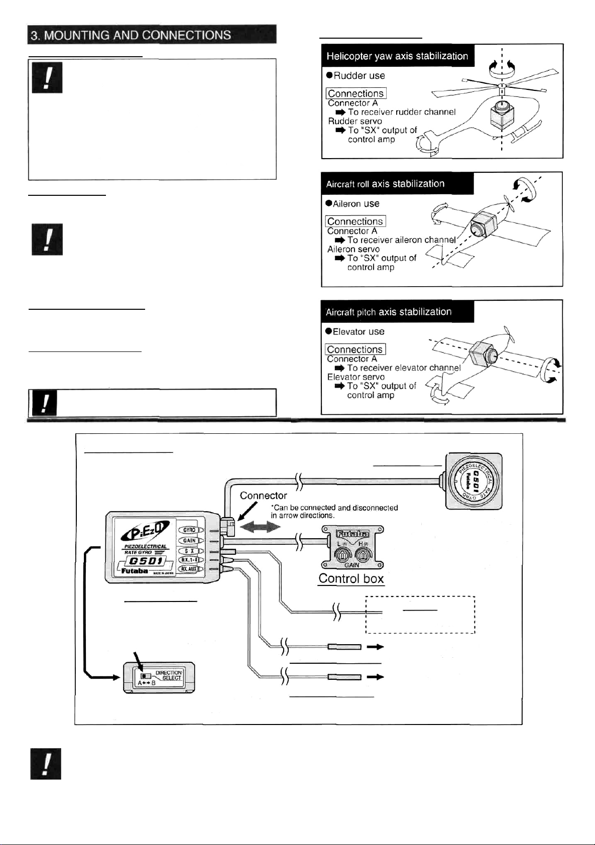
CONNECTIONS
Control amp
Gyro sensor
Adjust low sensitivity with the "L"
side sensitivity trimmer and high
sensitivity with the "H" side
sensitivity trimmer. When the
direction of the sensitivity switch is
opposite, set the direction using the
reverse function for gyro channel.
This is usually CH.5.
Servo
*Servo controlled by gyro.
Gyro output polarity switch
Connector
A
(black)
Connector B (red)
"When adjusting the linkage, always check the
polarity of the gyro output. If the polarity is opposite,
switch it with the direction select switch.
PRECAUTIONS WHEN TURNING ON THE RECEIVER POWER
Never move the aircraft for four or five seconds
after turning on the gyro power (shared with receiver).
Since initialization is automatically performed inside the
gyro immediately after the power is turned on, if the aircraft
-2-
is moved at that time, the neutral position will change. In this
case, turn on the power again.
At this time, the rudder servo (servo controlled by gyro)
moves to the home position after the servos on the other
channels, but this is normal.
To receiver rudder channel
(helicopter yaw axis stabilization)
To receiver channel 5
(sensitivity switching channel)
Page 3

There are two methods of adjusting the sensitivity.
(1) adjustment at the gyro (2) adjustment from the transmitter
The following shows the relation between mixing rate
and gyro sensitivity.
PMIX offset rate and sensitivity
PMIX offset rate
(1)Adjustment at the gyro
The sensitivity can be arbitrarily set over the 0 to 100%
range to correspond to the position of the transmitter sensitivity switch with the control box sensitivity high side and low
side trimmers.
(Hovering sensitivity)
When the CH5 (sensitivity
switching) switch is in the front
position, the sensitivity can be
adjusted from 0 to 100% with the
control box high side trimmer.
• Setting standard:
Approximately 75°
(Climbing sensitivity)
When the CH5 (sensitivity
switching) switch is in the rear
position, the sensitivity can be
adjusted from 0 to 100% with the
control box low side trimmer.
•Setting standard:
Approximately 45%
CH5
switch
Front
position
CH5
switch
Rear
position
Control box
High
side
Low
side
(2)Adjustment from the transmitter
When ATV function is used
(When reverse function is normal)
(Sensitivity adjustment range setting)
After deciding the upper and
lower limits of the sensitivity
adjustment range with the
control box high side and tow
side trimmers, adjust the
sensitivity using the transmitter
CH5 ATV function.
'Setting standard:
Upper limit Approximately 80%
Lower limit Approximately 40%
Lower limit
Setting
range
(Hovering sensitivity)
Adjust the CH5 switch Iront position ATV rate and adjust
the sensitivity high side.
The higher the ATV value, the higher the sensitivity.
• Setting standard:
ATV rate: Approximately 75%
(Climbing sensitivity)
Adjust the CH5 switch rear side ATV rate and adjust the
sensitivity low side.
The higher the ATV value, the lower the sensitivity.
• Setting standard:
ATV rate: Approximately 75%
Control box
Upper limit
+100% +30%+30% +100%
ATV function rate
CH5
switch
Front
position
CH5
switch
Rear
position
*With a PCM1024Z Series transmitter, the sensitivity can be
adjusted from 0 to 100% using the AFR function.
When using PCM1024Z Series transmitter program
mable mixing can be used.
1. First, set the sensitivity adjustment range to maximum at
the control box.
Low side
Fully
counter-
Control box
High side
Fully
clockwise
(maximum)
(Sensitivity adjustment
range setting)
Set the control box high side and low
side trimmers as shown at the right so
that the sensitivity can be adjusted
from 0 to 100% from the transmitter.
clockwise
(minimum)
2. Next, set the transmitter as follows for each flight condition.
Programmable mixing (PMIX) setting
(1) Set PMIX to one circuit.
(2) Select "OFS" (offset) type.
(3) Make CH5 (GYR) the slave channel.
In this state, the gyro sensitivity for each flight condition (hovering, forward flight, etc.) can be arbitrarily set
by setting the PMIX function rate.
-3-
Gyro sensitivity
(4) At this time, release the CH5 (GYR) switch by software as follows:
Function control(FNC) setting
Set the CH5 (GYR) switch to "NUL" (not used
state).
(5) Also set the CH5 (GYR) ATV function to the following value:
ATV function (ATV) setting
Set the CH5 (GYR) ATV function to 90% in both
directions.
The following describes the adjustment procedure when the
FP-G501 is used with a helicopter. Make these adjustments after all the connections are complete.
(All values are for when the FP-S9203 servo was used.)
Rudder linkage adjustment
Place the transmitter into the neutral state and adjust the
rod as described below so that the neutral position is near
the center.
1. Transmitter steering angle setting
Set the ATV function rudder left and right steering angles to
maximum.
2. Set the transmitter to the neutral state (including mixing).
-Set rudder subtrim to 0%.
-Set rudder trim to the center. —
-Set the throttle stick to the center. (When revolution mixing
is on.)
3. Turn on the power.
In this state, turn on the power in transmitter and receiver
order.
At this time, do not move the aircraft for about
four or five seconds.
4. Check the rudder direction.
Operate the transmitter stick and check the direction of the
rudders. If the direction is incorrect, reverse it.
5. Servo horn mounting
Change the servo horn spline so that the horn is perpendicular to the rod and servo.
"Make the length of the servo horn as
close to 16.5mm as possible. This may be
impossible, depending on the aircraft. In
this case, set the servo horn length to
maximum.
(Expansion horn: Futaba splined horn "A")
6. Gyro output polarity check
When the nose of the aircraft swings back and forth, check
the direction of rudder. If reversed, switch it with the gyro
control amp polarity switch.
If the aircraft is flown at reverse polarity, it may
swing severely in a fixed direction and this is
dangerous. Be sure that the gyro output polarity
is correct.
7. Sensitivity selector switch direction check
Set the control box high side trimmer for maximum sensitivity (fully clockwise) and the low side trimmer for minimum
sensitivity (fully counterclockwise) and check that the sensitivity switch high side (CH5 switch front position) and low
side (CH5 switch rear position) relationship is correct.
Page 4

Adjustment during flight
•Precautions before fliaht
Since the piezoelectric gyro uses a angular acceleration command control system, the rudder
has an excellent effect despite the high gain.
If hovering was performed at 100% dual rate (rudder) in
the past, reduce it to about 80%. When you want to perform a fast spin, use 100%. Since the rudder is very effective near the neutral position, exponential use (40 to
60% for hovering, 60 to 80% for forward flight)
Set rudder trim, rudder offset, and revolution mixing rate
to about 1/3 of their normal value. Start rudder offset
from neutral.
Sensitivity adjustment points
The suitable sensitivity depends on the fuselage, tail rotor,
tail drive shaft, servo, and servo horn. However, when starting adjustment, start with the following value as the set
value standard.
Sensitivity setting for hovering: 70 to 80%
Sensitivity setting for forward flight and aerobatics:
40 to 50%
'Adjust the sensitivity within the range at which hunting
does not occur when moved during hovering.
*lf the aircraft was suddenly stopped during operation at a
high angular acceleration, hunting may occur. Adjust the
sensitivity so that hunting does not occur over the necessary operating range.
*For forward flight, adjust the sensitivity within the range at
which does not occur hunting.
Trim
adjustment
If the trim changes, use the fuselage rod to adjust the trim to
near the neutral position.
Revolution mixing adjustment
Make the mixing amount small. If the mixing amount is
large, control is in the reverse direction. (About 1/3 of normal)
Rudder steering angle adjustment
Perform left and right pirouette. If the left and right rotation
speeds are different, reduce the high side by rudder ATV
function.
minutes and turn on the power after the temperature inside
the gyro has stabilized. Also, if the gyro is exposed to direct
sunlight or is mounted near the engine, the temperature
may change suddenly. Take suitable measures so that the
gyro is not exposed to direct sunlight, etc.
•Since the transmitter rudder channel is operated as the
angular acceleration command, do not adjust the rudder
channel throw (ATV function) when the aircraft is static. Use
ATV function to adjust the rudder effect.
• When the aircraft is static, a dead zone is created in transmitter stick operation. However, this is done to protect the
linkage and to restrict the servo output.
•Check the remaining receiver and gyro servo nicd battery
operating time during the adjustment stage and decide how
many flights are remaining.
(Fuselage maintenance precautions)
•The
rigidity
of
the fuselage tail has a large effect on gyro
performance. Therefore, proper maintenance from the beginning is essential for ultimate performance.
• Fuselage vibration also has an adverse affect on gyro operation. Make the fuselage vibration as small as possible.
Gyro FP-G501
Power supply voltage:
Current drain: 35mA (at 4.8V)
Dimensions: (Gyro) 1.18x1.18x1.22in (30x30x31mm)
(Control amp) 2.40x1.50x0.63in (61x38x16mm)
(Control box) 1.30x0.91x0.51 in (33x23x13mm)
Weight: 2.47oz (70g)
4.8V (shared with receiver)
Servo FP-S9203
Control system: Pulse width control
Power supply voltage: 4.8V (shared with receiver)
Output torque: 76.4oz-in (5.5kg-cm) (at 4.8V)
Operating speed: 0.11sec/60 deg (at 4.8V)
Dimensions: 1.59x0.79x1.48in (40.5x20x37.5mm)
Weight: 1.87oz(53g)
Before requesting repair, please refer to this instruction manual
again and verify your settings. If you are still experiencing
trouble, please request service as follows:
(Operating precautions)
• Do not move the aircraft for four or five seconds after turning on the gyro power (shared with receiver). Since initialization is automatically performed inside the gyro immedi-
ately after the power is turned on, if the aircraft is moved at
that time, the neutral position may change. In this case, turn
on the power again.
• If the gyro remains in the static state for a long time, the
neutral position may change. In this case, correct it by turning on the power again.
• Avoid sudden temperature changes. Sudden temperature
changes will cause the neutral position to change. For example, in the winter, do not fly immediately after removing
the model from inside a heated car and in the summer, do
not fly immediately after removing the model from inside an
air conditioned car. Allow the model to stand for about 10
Address
Your nearest Futaba dealer.
Repair information
Describe the trouble in as much detail as possible.
1) Symptom: Including the state of the set when the trouble
occurred.
2) Digital proportional set used: Transmitter, receiver, and
servo model numbers.
3) Fuselage: Fuselage name and mounting conditions.
4) Your name, address, and telephone number.
Warranty contents
Read the warranty card supplied with your set.
*The warranty contents differ with geographic locations.
-4-
 Loading...