

Page 1

53%2).34!,,!4)/.-!.5!,
-!2).%#$-02%#%)6%2
-3#$
Specifications and design are subject to change without notice.
Page 2
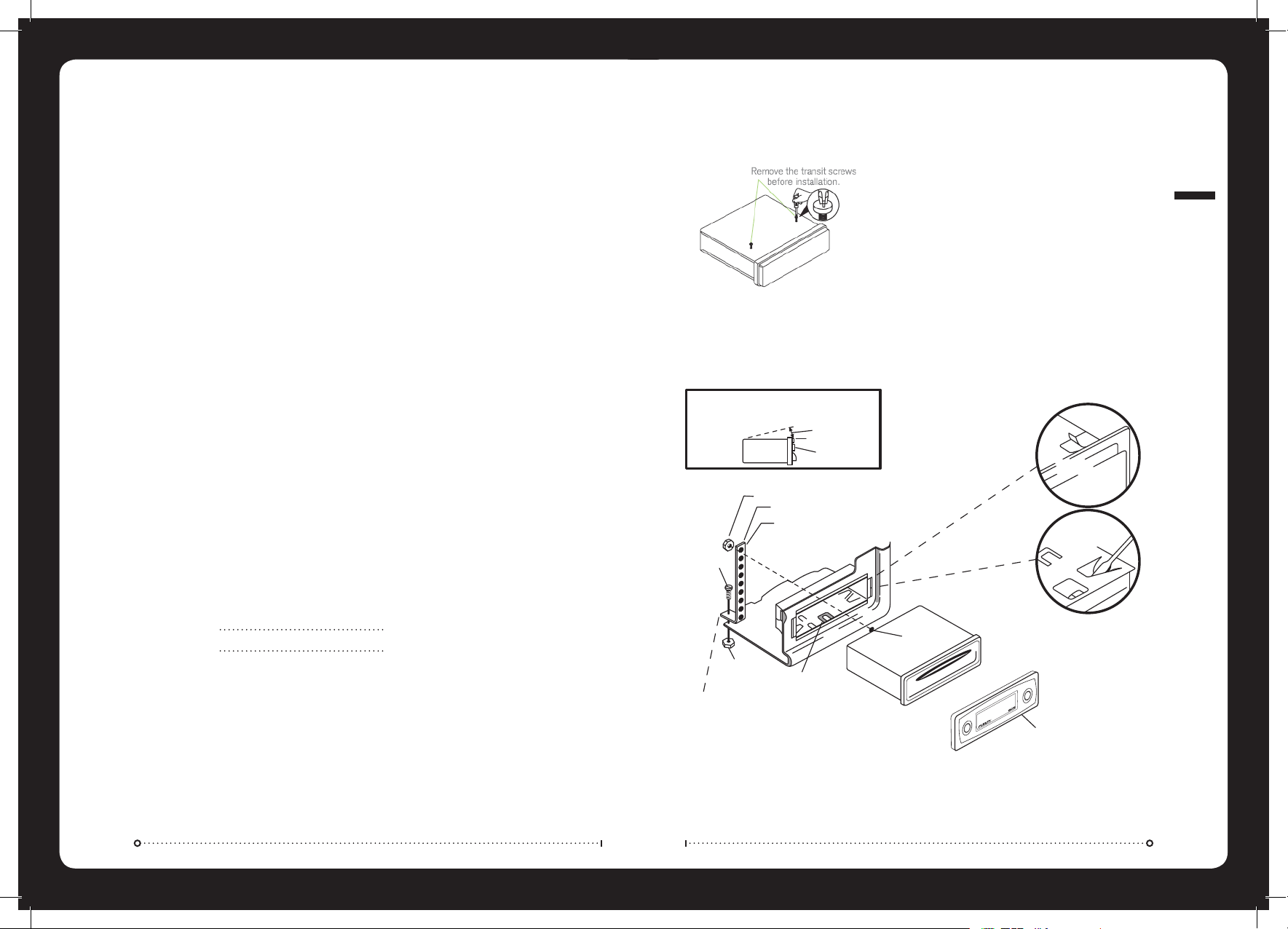
).34!,,!4)/.
Mounting Hole Dimensions 178mmW x 178mmD x 50mmH
Insert the sleeve into the mounting hole and select the appropriate tabs to secure it firmly by bending them into position.
Use the supplied strap to support the rear of the unit.
CAUTION:
FOR PROPER OPERATION OF THE CD PLAYER, THE CHASSIS MUST BE MOUNTED
WITHIN 20' OF HORIZONTAL. MAKE SURE THE UNIT IS MOUNTED WITHIN THIS
LIMITATION.
20' MAX
FRONT PANEL
SIDE VIEW
OF
CHASSIS
NUT(5MM)
NUT(5MM)
FASTEN THIS END TO A SECURE LOCATION.
DRIL HOLE IF NECESSARY.
MOUNTING SLEEVE
SCREW STUD
BEND BOTTOM TABS
DOWNWARD
DETACHABLE
FRONT PANEL
BEND TOP
TABS UPWARD
PERFORATED STRAP
FASTEN THIS END TO SCREW STUD ON
REAR OF CHASSIS
SCREW (5MM)
(%!$5.)4).34!,,!4)/.
Before installing the unit, please remove the two transit screws.
Note: When installing this unit on a vessel, use the two pieces of plastic film (supplied with the unit) to seal the
two holes after removing the screws, this will ensure the unit remains water resistant.
Version 5.0
RECORD YOUR PRODUCT DETAILS HERE:
Model Number
Date Of Purchase
Affix Receipt Here
INSTALLATION
#/.4%.43
).34!,,!4)/. PG
"544/.$%3#2)04)/. PG
'%.%2!,/0%2!4)/. PG
-%.53%,%#4)/.&5.#4)/. PG
2!$)//0%2!4)/. PG
#$/0%2!4)/. PG
-0/0%2!4)/. PG
I0OD/0%2!4)/. PG
53"/0%2!4)/. PG
3500/24%$-07-!&/2-!43 PG
4%#(.)#!,30%#)&)#!4)/.3 PG
45.%2 PG
./4%3 PG
Page 3
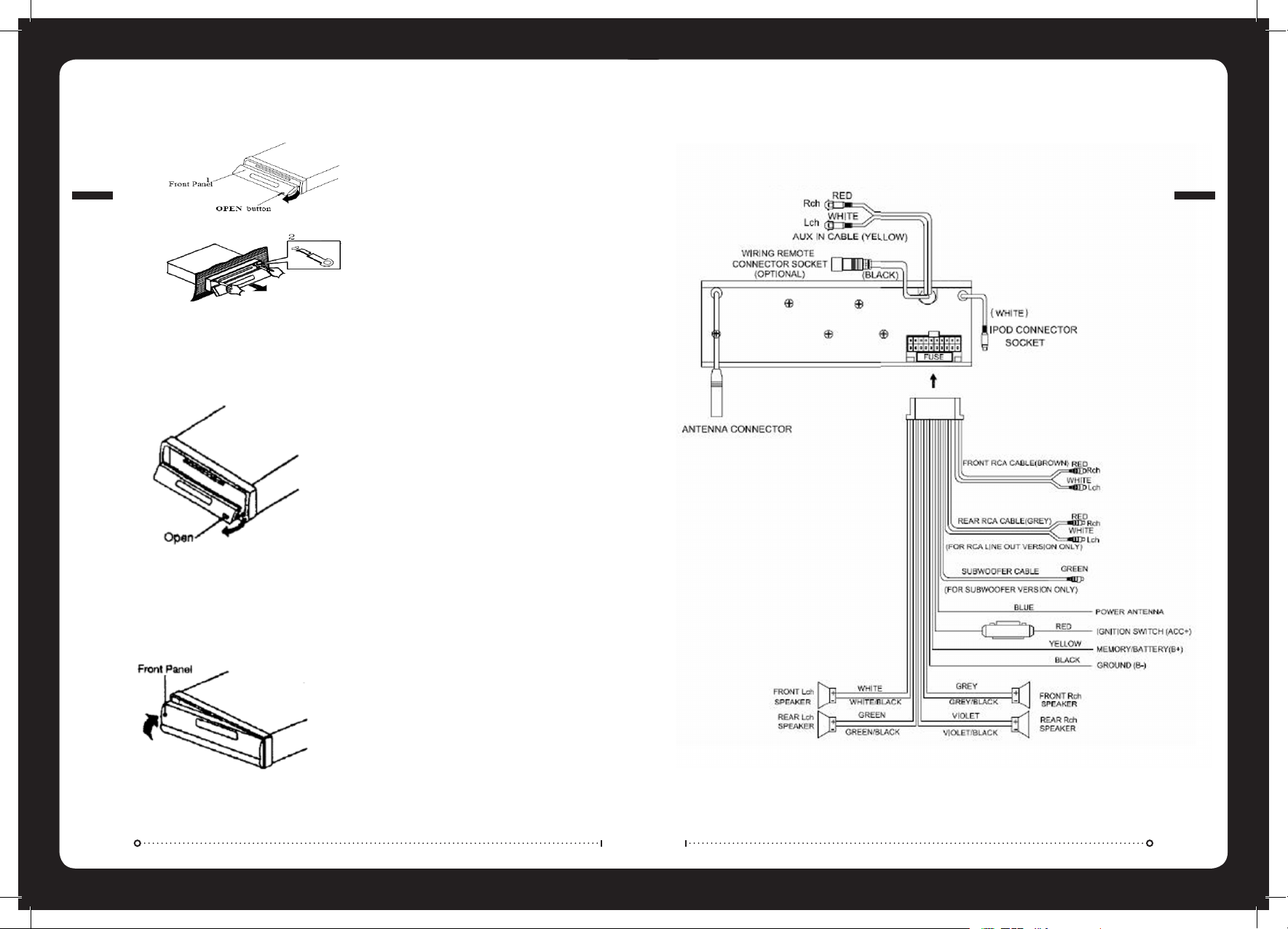
7)2).'#/..%#4)/.3
$%4!#().'&2/.40!.%,
2%!44!#().'&2/.40!.%,
2%-/6).'4(%5.)4
1. To detach the front panel press the open button
2. Then press the release button on the front underside edge and slide the face toward you.
3. A protective case is supplied to store your removeable front panel in.
1. Press the open button on the face plate
2. Insert the supplied keys into the grooves in the housing until they click (as shown)
3. Pull the levers towards you and slowly remove the unit from the cage.
1. If the panel bracket is in the open position slide the panel back on into position.
2. If the panel bracket is in the upright position clip one end in firstly and then clip the other end in and the
panel will lock in place.
WIRING CONNECTIONS
REMOVING THE UNIT
Page 4

'%.%2!,/0%2!4)/.
POWER ON/OFF
Press the power ON/OFF button (9)
FRONT PANEL RELEASE
Press OPEN button (7) to open the front panel
SOUND ADJUSTMENT
Press the SEL/MENU button (10) repeatedly to cycle the audio mode through bass, treble, balance and fader modes.
Press the VOLUME UP button (12) or VOLUME DOWN button (11) to adjust the selected mode.
BASS TREBLE BALANCE FADER
SETTING THE CLOCK
Press and hold the DISPLAY Button (15) until the clock
is displayed and flashes. Press the button (17)
to change the minutes and the button (16) to
change the hours. Press the DISPLAY button (15) to
confirm and exit.
MUTE
In Radio/Aux mode, press MUTE button (3) to mute the
audio. Press again to resume.
LOUDNESS
Press and hold the BND/LOU/ENT button (13) to
reinforce the bass output. Press again to cancel.
MODE SELECTION
Press the MODE/SW button (6) to cycle through the
source modes. Only active modes will be displayed. Eg.
If there is no CD loaded CD mode will not be selectable.
SUBWOOFER LINE OUT
Press and hold MODE/SW button (6) to activate the
Subwoofer output. Repeat to deactivate
GENERAL OPERATION
EQUALIZATION
Press the EQ button (19) repeatedly to cycle through
and select the EQ option you desire.
ESP
Electronic shock protection provides a 10 second read
ahead buffer.
RESET BUTTON
The RESET button is located in the housing of the unit
button (27) and must be activated with a ballpoint pen
or something similar under the following conditions.
1. An error symbol is displayed
2. Function buttons do not operate correctly
"544/.$%3#2)04)/.
&2/.40!.%,
1. MON -Mono/Stereo
2. LOCAL/DIST Station
3. Mute
4. (eject button)
5. Disc Slot
6. MODE/SUB.W
7. OPEN
8. Liquid Crystal Display
9. Power ON/OFF
10. SEL/MENU
11. - (volume down button)
12. + (volume up button)
13. BND/LOU/ENT
14. Preset station buttons (1-6)
15. DISPLAY
16. (Rewind)
17. (Forward)
18. AS/PS-Auto store preset scan
iPod Menu
19. EQ (equaliser)
20. / Play/Pause
21. SCN (track preview)
22. RPT (repeat)
23. SHF (shuffle)
24. DIR (down)
25. DIR (up)
26. USB Interface
27. Reset button
BUTTON DESCRIPTION
Page 5

#$/0%2!4)/.
If there is no CD loaded press OPEN Button (7) and gently insert the disc until you feel some resistance. The CD
will be drawn into the unit and playback will begin.
If there is a CD already in the unit press the MODE button (6) until CD mode is displayed.
EJECTING A DISC
Press the OPEN button (7) and press the EJECT button
(4).
PAUSE PLAY
Press PAUSE/PLAY button (20) to pause play, press
again to resume.
TRACK SELECTION
Press the button (16) to skip to the previous
track or Button (17) to skip to the next track.
Press and hold (17) to FAST FORWARD and (16) to
FAST REWIND.
REPEAT TRACK
Press RPT button (22) to continuously repeat the
track. Press again to cancel.
SHUFFLE
Press the SHF button (23) to play the tracks in a
random order. Press again to cancel.
SCAN TRACKS
Press SCN button (21) to play a few seconds of each
track. Press again to cancel and continue playing the
track.
2!$)//0%2!4)/.
Press the MODE button (6) to select the Radio mode.
SELECTING FREQUENCY BAND
Press BND/LOU/ENT button (13) to cycle through and select the desired band
-%.53%,%#4)/.&5.#4)/.
Press and hold SEL button (10) to enter Menu Select Mode. Press the VOLUME UP button (12) or the VOLUME
DOWN button (11) to adjust the BEEP function.
BEEP 2nd MODE
Only beeps on press and hold functions.
BEEP ALL
Beeps on all key presses.
BEEP OFF
Beeps disabled.
FM 1 FM 2 FM 3 AM
SELECTING STATION
Auto Seek
Press the button (16) or button (17) to
activate the automatic seek function up or down the
frequency spectrum.
Manual
Press and hold the button (16) or the
button (17) until MANUAL appears on the screen. If
neither button is pressed for several seconds the unit
will switch to AUTO SEEK.
AUTOMATIC MEMORY STORING AND PRESET SCAN
Automatic Memory Storing
Press and hold the AS/PS button (18) and the unit will
search for the strongest signals and then store them
in the presets.
Preset Scan
Press the AS/PS button (2) to preview all stored
preset stations. Stations with weak signal levels are
bypassed.
STORING PRESET STATIONS
There are six presets available for each band (FM1,
FM2, FM3 and AM).
1. Select the desired band and tune in the station
you want to store.
2. Press and hold the PRESET button (14) 1-6
until a beep is heard to confirm and the preset
number is displayed.
MONO/STEREO
Press MON button (1) to select Mono or Stereo mode.
LOCAL/DISTANT SELECTION
Press LOCAL/DIST Station button (2) to select between
local and distant stations. Local setting for reception of
strong station, and a distant setting for reception of
weaker stations.
CD OPERATION
MENU SELECTION
Page 6

I0OD/0%2!4)/.
There are two options to connect an iPod to the unit:
Option 1: Via the MS–IP15L accessory cable (available separately).
Option 2: Via the MS–IPDOCK Marine External Dock (available separately). For a full list compatible iPods see the
MS–IPDOCK manual product manual or visit www.fusionelectronics.com
Option 3: Via the auxiliary input connectors.
IPOD MENU SEARCH
During playback press iPod Menu button (18) to
display menu. Press the Volume Down button (11)
or Volume Up button (12) to navigate the menu and
search by the following catagories.
PLAYLIST/ARTIST/ALBUM/GENRE/SONG/COMPOSER Press
SEL/MENU button (10) to enter the selected sub menu
and search within the folder in the same manner
pressing Volume Down/Up buttons (11, 12) and
SEL/MENU (10).
DISPLAY
During playback press DISP button (15) to display
current song information
SONG TITLE/ARTIST/ALBUM NAME/CLOCK/TRACK/PLAY TIME.
PAUSE PLAY
Press PAUSE/PLAY button (20) to pause play, press
again to resume.
REPEAT TRACK
During playback press RPT button (22) and RPT will be
displayed press again to cancel.
RANDOM PLAY
During playback press SHF button (23) once the
current selection has finished playing, all songs in the
current category will play in a random order. Press
again to cancel.
TRACK SELECTION
During playback press button (17) to select
the next track. Press button (16) to play the
previous track. If the song has been playing more than
1 second it will resume play from the beginning, if
playing more than 2 seconds the previous song will
be selected.
FAST FORWARD
Press and hold button (17) for 2 seconds to
activate.
REWIND
Press and hold button (16) for 2 seconds to
activate.
AUXILIARY INPUT
Connect an Auxiliary device to the RCA connectors on
the rear of the unit. Press MODE button (6) to select
AUX.
TRACK SELECTION
Press the button (16) to skip to the previous
track or button (17) to skip to the next track.
DIRECTORY SELECTION
Press DIR/DOWN button (24) or DIR/UP button (25) to
navigate the directory. If your tracks are arranged in
albums this function steps up and down albums.
DIRECT TRACK SEARCH
Press the iPod Menu button (18) once to enter the
search mode then select the track number as follows:
Method 1: VOLUME +/- button (11& 12) and confirm by
pressing the BND/LOU/ENT button (13).
Method 2: Direct numeric entry with the M1-M6, MODE
(7), TUNE (8,9), DISP (0) keys and confirm by pressing
the BND/LOU/ENT button (13).
DIRECTORY OR FILE NAME SEARCH
Press the iPod Menu button (18) twice to enter the
search mode.
Method 1: Characters are entered via the VOLUME +/button (11 & 12). Characters available are A-Z, 0-9,
_,-,+. Enter the desired character and confirm with the
SEL/MENU button (10) the cursor will move to the next
digit. Once complete press the BND/LOU/ENT button
(13) to begin search.
Method 2: Direct numeric entry as shown in the
following table:
-0/0%2!4)/.
SEARCHING ROOT DIRECTORY
Press the iPod Menu button (18) three times to enter
the search mode. Press the (16) and (17)
buttons to select the directory or file name displayed
then press BND/LOU/ENT to play the selection.
SEARCHING CURRENT DIRECTORY
Press the iPod Menu button (18) four times to enter
the search mode. Press the (16) and (17)
buttons to select the directory or file name displayed
then press BND/LOU/ENT to play the selection.
PAUSE PLAY
Press PLAY/PAUSE/MUTE button (20) to pause MP3 play.
Press to resume.
REPEAT SONG OR FOLDER
Press RPT button (22) to continuously repeat the
current song. Press and hold RPT to repeat all songs in
the current folder. Press again to cancel.
SHUFFLE
Press SHF button (23) to play all songs in random.
Press and hold to select a folder and play contents of
folder in random order. Press again to cancel.
PREVIEW ALL SONGS
Press SCN button (21) to play the first several seconds
of each song. Press and hold to play the first several
seconds of the first track in each folder. Press again
during intro to play entire track.
DISPLAY INFORMATION
Press DISP button (15) to display the Clock, ID3 Tag (if
available: Directory name, Song title, Artist name).
WMA OPERATION
Operation of discs recorded in this format is the same
as MP3.
iPod OPERATION
MP3 OPERATION
AS/PS Mode Select BND/LOU ENT
M1 A, B, C, 1 M2 D, E, F, 2
M3 G, H, I, 3 M4 J, K, L, 4
M5 M, N, O, 5/
Directory DOWN
M6 P, Q, R, 6/
Director UP
MOD S, T, U, 7 TUNE DOWN V, W, X, 8
TUNE UP Y, Z, SPACE, 9 PUSH SEL Character Shift
Right
DSP _, -, +, 0 VOL KNOB
Character Select
(A, B-8, 9, 0)
Page 7

HANDLING COMPACT DISCS (CD/CD-R/CD-RW)
- Avoid touching the surface
- Avoid exposing the disc to direct sunlight
- Ensure the disc is clean
- Ensure the disc is not scratched or damaged.
PLAYBACK OF CD-R/CD-RW
- If your CR-R/CD-RW will not play. Ensure that the last recording session was closed or finalised.
SUPPORTED MEDIA
- Only use compact discs with the CD logo’s on the label as listed below.
- If you use compact discs without the above logo’s, correct performance cannot be guaranteed
- You can play audio discs recorded on CD-R (Recordable) and CD-RW (Re Writable) media
Windows Media and the Windows logo are trademarks, or registered trademarks of Microsoft Corporation in the United States and/or other
countries. Apple, the Apple logo, iPod and iTunes are Trademarks of Apple Computer, Inc, registered in the U.S. and other countries.
“MPEG Layer-3 audio coding technology licensed from Fraunhofer IIS and Thompson.”
“Supply of this product only conveys a licence for private, non-commercial use and does not convey a licence nor imply any right to use this
product in any commercial (i.e. revenue generation) real time broadcasting (terrestrial, satellite, cable and/or any other media), broadcasting/
streaming via internet, intranets and/or other networks or in other electronic content distribution systems, such as pay-audio or audio-on-
demand applications. An independent license for such use is required. For details, please visit
http://www.mp3licensing.com”
53"/0%2!4)/.
Connect the USB device via the USB interface (26) and playback of MP3/WMA files will start automatically. USB
mode can be selected with the MODE button (6). Operation of the USB is identical to MP3 operation. (see page 10
CAUTION: To safely eject the USB device ensure you change the mode to another source before removing the device.
NOTE: This product does not support all USB/MP3 players.
WARNING: Ensure when connecting an MP3 player via the USB interface that it has rechargeable batteries NOT standard
batteries in use as this may cause the batteries to explode.
3500/24%$-07-!
&/2-!43
NOTES ON MP3 FILES
1. The disc must be in the ISO9660 level 1 or level 2 format.
2. When naming a MP3 file, be sure the file name extension is “MP3”.
3. For a non-MP3 file, even though the file name extension is “MP3”, the unit cannot recognise it.
1) MP3: Compliant with layer 3 of MPEG1
-Sampling rates (kHz): 44.1
-Bit rates (kbps): 16, 24, 32, 40, 48, 56, 64, 80, 96, 112, 128, 144, 160, 192, 224, 256, 320 variable bit
rates supported.
2) WMA: Compliant with Windows Media Audio 9
-Sampling rates (kHz): 44.1
-Bit rates (kbps): 32 to 192 does not support DRM and Lossless, Professional and Voice of WMA9
MP3/WMA
Max Files 999
Max Folders 500
Folder Depth 8
HANDLING CD’S
USB OPERATION
Page 8

PUBLISHED BY FUSION ELECTRONICS LIMITED:
© Copyright 2009 by FUSION Electronics Limited.
All rights reserved. Specifications and design are
subject to change without notice.
YOU CAN HELP PROTECT THE ENVIRONMENT!
Please remember to respect the local regulations:
Hand in the non-working electrical equipment
to an appropriate waste disposal center.
.............................................................................................................................................................................................................
.............................................................................................................................................................................................................
.............................................................................................................................................................................................................
.............................................................................................................................................................................................................
.............................................................................................................................................................................................................
.............................................................................................................................................................................................................
.............................................................................................................................................................................................................
.............................................................................................................................................................................................................
.............................................................................................................................................................................................................
.............................................................................................................................................................................................................
.............................................................................................................................................................................................................
.............................................................................................................................................................................................................
.............................................................................................................................................................................................................
.............................................................................................................................................................................................................
.............................................................................................................................................................................................................
.............................................................................................................................................................................................................
.............................................................................................................................................................................................................
.............................................................................................................................................................................................................
.............................................................................................................................................................................................................
.............................................................................................................................................................................................................
.............................................................................................................................................................................................................
.............................................................................................................................................................................................................
.............................................................................................................................................................................................................
./4%3
4%#(.)#!,30%#)&)#!4)/.3
Operating Voltage DC 12volts, Negative Ground
Chassis Dimensions 178(W) x 178(D) x 50(H)
Output Power 40 Watts x 4 Channels
Max Current Draw 15 amps
Output RCA line level Front and Rear Channels
Subwoofer RCA Output
Output Impedance 4-8 Ohms
45.%2
EUROPE
Tuning Range FM: 87.5 to 108 MHZ
Sensitivity (S/N =30dB) 3µV
Tuning Range AM: 522 to 1620 KHZ
Sensitivity (S/N=20dB) 32dBu
NOTES
TECHNICAL SPECIFICATIONS
 Loading...