

Page 1
®
FUSION® MS-BB300 Installation
Instructions
Important Safety Information
WARNING
Failure to follow these warnings and cautions could result in
personal injury, damage to the vessel, or poor product
performance.
See the Important Safety and Product Information guide in the
product box for product warnings and other important
information.
This device must be installed according to these instructions.
Disconnect the vessel's power supply before beginning to install
this product.
Before applying power to this product, make sure it has been
correctly grounded, following the instructions in the guide.
CAUTION
Always wear safety goggles, ear protection, and a dust mask
when drilling, cutting, or sanding.
NOTICE
When drilling or cutting, always check what is on the opposite
side of the surface.
You must read all installation instructions before beginning the
installation. If you experience difficulty during the installation,
contact FUSION Product Support.
Software Updates
For best results, you should update the software in all FUSION
devices at the time of installation to ensure compatibility.
Go to www.fusionentertainment.com/marine to download the
latest software. Software updates and instructions are available
on your device product page.
• To avoid interference with a magnetic compass, the device
should be installed at least 203 mm (8 in.) away from a
compass.
Mounting the FUSION BB300 Device
NOTICE
If you are mounting the device in fiberglass, when drilling the
pilot holes, it is recommended to use a countersink bit to drill a
clearance counterbore through only the top gel-coat layer. This
will help to avoid cracking in the gel-coat layer when the screws
are tightened.
NOTE: Stainless-steel screws may bind when screwed into
fiberglass and overtightened. It is recommended to apply an
anti-seize lubricant to the screws before installing them.
NOTE: Screws are included with the device, but they may not
be suitable for the mounting surface.
Before you mount the device, you must select a mounting
location and determine what screws and other mounting
hardware are needed for the surface.
Place the device in the mounting location and mark the
1
location of the pilot holes.
Drill a pilot hole for one corner of the device.
2
Loosely fasten the device to the mounting surface with one
3
corner and examine the other three pilot-hole marks.
Mark new pilot-hole locations if necessary, and remove the
4
device from the mounting surface.
Drill the remaining pilot holes.
5
Secure the device to the mounting location.
6
Connection Considerations
The device must be connected to power, either the boat ignition
or an external switch, a NMEA 2000® network, speakers, and
media input sources to function correctly. You should carefully
plan the layout of the device, the NMEA 2000 network, the
speakers, and your input sources before making any
connections.
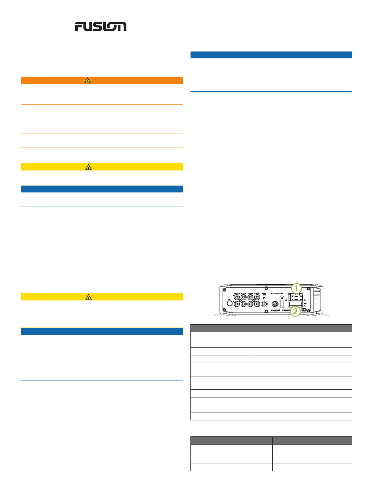
Connector Identification
Mounting Considerations
CAUTION
In high ambient temperatures and after extended use, the
device enclosure may reach temperatures deemed dangerous
to touch. Therefore the unit must be installed in a location where
it will not be touched during operation.
NOTICE
This device should be mounted in a location that is not exposed
to extreme temperatures or conditions. The temperature range
for this device is listed in the product specifications. Extended
exposure to temperatures exceeding the specified temperature
range, in storage or operating conditions, may cause device
failure. Extreme-temperature-induced damage and related
consequences are not covered by the warranty.
• The device must be mounted in a location where it is not
submerged.
• The device must be mounted in a location with adequate
ventilation where it is not exposed to extreme temperatures.
• The device should be mounted so that the cables can be
connected easily.
• To achieve IPX3 water ingress protection and optimal heat
sink cooling, the device must be mounted on a vertical
surface with the connectors pointing downward.
• The device can be mounted on a horizontal surface, but such
positioning might not achieve IPX3 water ingress protection.
Connector Connects to
ANT External AM/FM antenna
AUX IN 1 Stereo line-level RCA auxiliary source
AUX IN 2 Stereo line-level RCA auxiliary source
ZONE 3 Separate amplifier and speakers
SUB OUT Mono line-level subwoofer (tied to ZONE 3)
WIRED REMOTE NMEA
2000
SXM TUNER SiriusXM® tuner
USB USB-compatible media device
À
Á
for amplifier
FUSION NRX or NMEA 2000 network
Power and speakers
Reserved for future use
Wire Identification
Wire Function Wire Color Notes
Power (+) Yellow This should be connected to a
Ground (-) Black
constant 12 Vdc source capable of
supplying 15 A.
February 2017 Printed in Thailand 190-01914-02_0B
Page 2
Wire Function Wire Color Notes
Ignition Red This should be connected to a
Amplifier on Blue/white This is connected only when using
Mute Brown/white When connected to ground, this
Speaker zone 1 left
(+)
Speaker zone 1 left
(-)
Speaker zone 1 right
(+)
Speaker zone 1 right
(-)
Speaker zone 2 left
(+)
Speaker zone 2 left
(-)
Speaker zone 2 right
(+)
Speaker zone 2 right
(-)
White
White/black
Gray
Gray/black
Green
Green/black
Purple
Purple/black
separate switched 12 Vdc
connection, such as an ignition
bus, to turn the device on and off.
If you are not using a switched
12 Vdc connection, you must
connect this to the same source
as the yellow (power) wire.
an external amplifier on ZONE 3
and on SUB OUT (optional).
mutes the audio or switches the
input to AUX2. This is available in
the settings menu.
Connecting to Power
When connecting the stereo to power, you must connect both
power wires. The yellow power wire should be connected
directly to the battery, or connected using a 15 A isolator switch.
This provides power to the stereo and a constant trickle-power
standby feed. The red signal wire should be connected to the
same battery through the ignition or another manual switch to
turn the stereo on and off.
If you are not routing the red wire to the ignition or another
manual switch, you can connect the yellow to the red, and
connect them to the positive (+) battery terminal. You should put
a fuse on the red wire.
If it is necessary to extend the yellow power and black ground
wires, use 14 AWG (2.08 mm2) wire. For extensions longer than
1 m (3 ft.), use 12 AWG (3.31 mm²) wire.
If it is necessary to extend the red signal wire, use 22 AWG
(0.33 mm2) wire.
Route the yellow power À and black ground Á wires to the
1
battery and route the wiring-harness plug to the stereo.
Do not connect the wiring harness to the stereo until all of the
bare wire connections have been made.
• Connect the yellow wire to the positive (+) battery
terminal, and route the red signal wire  to the ignition or
another manual switch Ã.
• Connect the yellow wire to the red, and connect them to
the positive (+) battery terminal.
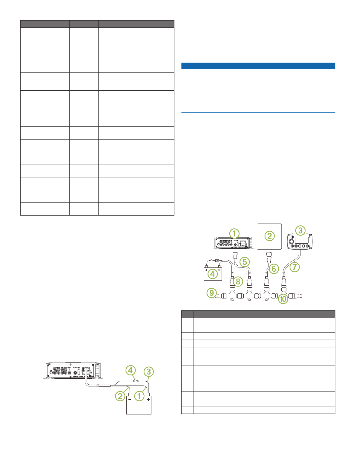
NMEA 2000 Connection Considerations
NOTICE
If you purchased the stereo and remote as a bundle (FUSION
MS-BB300R), do not use the included adapter cable
(CAB000862) to connect the FUSION BB300 stereo to an
existing NMEA 2000 network. Existing networks are normally
powered separately. You must obtain a non-powered drop cable
(CAB000863) from FUSION to connect to existing NMEA 2000
networks.
The FUSION MS-BB300 stereo can connect to an existing
NMEA 2000 network or to a FUSION NRX remote control.
Through the NMEA 2000 network, you control the FUSION MSBB300 device using a compatible chartplotter or FUSION NRX
remote control.
The FUSION MS-BB300R stereo and remote bundle package
includes the cables needed to connect the FUSION BB300
stereo to a stand-alone FUSION remote control network. If you
need to connect the FUSION MS-BB300R stereo and remote
bundle to an existing NMEA 2000 network, you must obtain a
non-powered drop cable (CAB000863) from FUSION.
The FUSION MS-BB300 stereo package includes a NMEA 2000
drop cable to connect the FUSION BB300 stereo to an existing
NMEA 2000 network. A standard NMEA 2000 drop cable is not
compatible with the connector on the device, although the
included cable can be extended to a maximum length of 2 m
(6 ft.) using a standard NMEA 2000 cable.
Item Description
FUSION BB300 device
À
Compatible chartplotter
Á
FUSION NRX remote control
Â
12 Vdc power source with an ignition or in-line switch
Ã
FUSION BB300 NMEA 2000 drop cable
Ä
This can be extended to a maximum length of 2 m (6 ft.) using a
standard NMEA 2000 cable.
NMEA 2000 drop cable
Å
FUSION NRX remote control drop cable.
Æ
This can be extended to a maximum length of 2 m (6 ft.) using a
standard NMEA 2000 cable.
NMEA 2000 power cable
Ç
NMEA 2000 terminator or backbone cable
È
NMEA 2000 T-connector
É
Connect the black wire to the negative (-) battery terminal.
2
Select an option:
3
2 FUSION MS-BB300 Installation Instructions
Subwoofer Connection Considerations
This device supports output to a powered subwoofer from ZONE
3 (optional).
Page 3

The subwoofer port on the device outputs a mono line-level
signal from both RCA connectors. The port output audio level is
linked to ZONE 3.
• If your subwoofer amplifier has two RCA input connectors,
you should connect both connectors to the device.
• If your subwoofer amplifier has one RCA input connector, you
can connect it to either subwoofer output RCA connector on
the device, because the two RCA subwoofer outputs are
parallel.
• Because the subwoofer output is linked to the ZONE 3
output, you must connect the blue wire from the wiring
harness to the subwoofer amplifier to provide a signal to turn
it on.
Speaker Amplifier Connection Considerations
In addition to the two stereo speaker zones available through
the wiring harness, this stereo can be connected to a separate
amplifier and speakers through the ZONE 3 connection
(optional).
• The blue wire from the wiring harness must be connected to
the amplifier to provide a signal to turn on the amplifier with
the stereo. If it is necessary to extend this blue signal wire,
use 22 AWG (0.33 mm2) wire.
• The audio output is a stereo line-level output over standard
RCA cable.
Installing the USB and 3.5 mm Socket
The USB and 3.5 mm socket is provided only with the FUSION
MS-BB300R stereo and remote bundle. You may purchase the
USB and 3.5 mm socket as an accessory (MS-CBUSB3.5).
Before installing the socket, make sure the cables will reach the
mounting location and the ports on the back of the device. If
needed, the RCA cables can be extended using a standard
stereo RCA extension cable.
To allow for a proper seal, the mounting surface should be no
thicker than 15 mm ( 5/ 8 in.).
Remove the nut À from the socket and separate it from the
1
connected cable by pulling through one connector Á at a
time.
Stereo Information
Specifications
General
Dimensions (L × W × H) 99.6 × 235 × 66 mm (3.94 × 9.25 × 2.63 in.)
Weight 0.88 kg (1.96 lb.)
Water resistance IPX3: Protected against spraying water when
Operating temperature From 0 to 50°C (from 32 to 122°F)
Storage temperature From -20 to 70°C (from -4 to 158°F)
Input voltage 10.8 to 16 Vdc negative ground
Fuse rating 15 A
NMEA 2000 LEN 1 (50 mA)
Compass-safe distance 203 mm (8 in.)
Audio Amplifier
Output music power per channel 50 W
Total output music power 200 W
Speaker impedance 4 Ohm per channel
Total harmonic distortion (1 W output, 4 ohm load,
from 20 Hz to 20 kHz)
Pre-output voltage 3 V peak
Current (standby with ignition off) < 3 mA
Current (max.) 15 A
Current (muted) < 800 mA
Inputs and Outputs
AUX IN 1 and
AUX IN 2
ZONE 3 RCA stereo line output
SUB OUT RCA dual mono line output (ZONE 3)
ANT Motorola connector (standard AM/FM antenna
USB USB-A industry standard
tilted up to 60 degrees vertically.
0.04 typical
< 0.1% max.
RCA stereo line input for sources such as CD, DVD,
and MP3 player
connector)
Compatible with USB flash drives audio playback with
supported audio formats and MTP devices
USB works with iPod touch® (2nd through 5th
generation), iPod classic®, iPod nano®(4th through 7th
generation), iPhone® 5, iPhone 4s, iPhone 4, iPhone
3Gs, iPhone 3G
Tuner Europe and
FM radio
frequency range
FM frequency
Do not remove the protective cover  from the socket.
Mark the mounting location of the socket and drill a 30 mm
2
(1 3/16 in.) hole through the mounting surface.
From the front of the mounting surface, feed the cables
3
through the hole by inserting one connector at a time, and
pull the cables through until the socket rests in the hole.
To ensure proper orientation, the USB socket à should be on
the top.
Place the nut over both the USB and 3.5 mm audio cables,
4
thread it along the cables to the USB and 3.5 mm socket, and
fasten the socket to the surface.
If necessary, route the USB cable to the stereo and connect it
5
to the USB port.
If necessary, route the 3.5 mm connector cable to the stereo
6
and connect it to the AUX IN 1 or AUX IN 2 port.
FUSION MS-BB300 Installation Instructions 3
step
AM radio
frequency range
AM frequency
step
Registering Your FUSION MS-BB300
Help us better support you by completing our online registration
today.
• Go to www.fusionentertainment.com.
• Keep the original sales receipt, or a photocopy, in a safe
place.
Getting the Owner's Manual
You can get the latest owner's manual and translations of
manuals from the web.
Go to www.fusionentertainment.com/marine.
1
Select your product.
2
Select Manuals & Downloads.
3
Australasia
87.5 to 108 MHz 87.5 to
50 kHz 200 kHz 50 kHz
522 to 1620 kHz 530 to
9 kHz 10 kHz 9 kHz
USA Japan
107.9 MHz
1710 kHz
76 to 95 MHz
522 to
1620 kHz
Page 4

Select a manual.
TA-2013/2178
4
© 2015–2017 Garmin Ltd. or its subsidiaries
Garmin®, the Garmin logo, and the FUSION® logo are trademarks of Garmin Ltd. or its
subsidiaries, registered in the USA and other countries. Fusion and FUSION-Link™ are
trademarks of Garmin Ltd. or its subsidiaries. These trademarks may not be used
without the express permission of Garmin.
Apple®, the Apple logo, iPod®, iPod touch®, iPod classic®, iPod nano®, and iPhone®
are trademarks of Apple Inc., registered in the U.S. and other countries. Android™ is a
trademark of Google Inc.
SIG, Inc. and any use of such marks by Garmin is under license. NMEA®, NMEA
2000®, and the NMEA 2000 logo are registered trademarks of the National Marine
Electronics Association. Sirius, XM and all related marks and logos are trademarks of
Sirius XM Radio Inc. All rights reserved. Other trademarks and trade names are those of
their respective owners.
Made for iPhone 5, iPhone 4s, iPhone 4, iPhone 3GS, iPhone 3G, iPod touch (2nd
through 5th generation), iPod classic, and iPod nano (4th through 7th generation).
"Made for iPod and iPhone" means that an electronic accessory has been designed to
connect specifically to an iPod or an iPhone respectively, and has been certified by the
developer to meet Apple performance standards. Apple is not responsible for the
operation of this device or its compliance with safety and regulatory standards. Please
note that the use of this accessory with an iPhone may affect wireless performance.
Bluetooth® word mark and logos are owned by the Bluetooth
© 2015–2017 Garmin Ltd. or its subsidiaries
www.fusionentertainment.com
 Loading...