

Page 1

Installation Manual
MARINE RADAR FR-2125V
SAFETY INSTRUCTIONS ......................................................i
SYSTEM CONFIGURATION ............................................... iii
EQUIPMENT LISTS.................................................................iv
MOUNTING
1.1 Antenna Unit .................................................................... 1-1
1.2 Display Unit...................................................................... 1-5
WIRING
2.1 Antenna Unit .................................................................... 2-1
2.2 Display Unit...................................................................... 2-5
2.3 Changing AC Power Specification................................. 2-12
INITIALIZA TION AND ADJUSTMENT
3.1 Tuning Initialization .......................................................... 3-1
3.2 Accessing Menus for Initialization and Adjustment.......... 3-1
3.3 Adjusting Video Signal Level ........................................... 3-1
3.4 Heading Alignment........................................................... 3-2
3.5 Adjusting Sweep Timing................................................... 3-3
3.6 Suppressing Main Bang................................................... 3-3
3.7 Confirming Magnetron Heater Voltage ............................ 3-4
3.8 Initial Setting Menus ........................................................ 3-5
INSTALLATION OF OPTIONAL EQUIPMENT
4.1 Gyro Converter GC-8....................................................... 4-1
4.2 ARP Board ARP-26.......................................................... 4-8
4.3 RP Board RP-26 ............................................................ 4-10
4.4 Performance Monitor PM-30.......................................... 4-15
4.5 Alarm Kit ........................................................................ 4-16
4.6 AC-DC Conversion Kit ................................................... 4-18
4.7 Connection of Rate-of-Turn Signal ................................ 4-19
4.8 V-Console Kit ................................................................. 4-20
PACKING LISTS.................................................................... A-1
OUTLINE DRA WINGS........................................................D-1
INTERCONNECTION DIAGRAM................................... S-1
SCHEMATIC DIAGRAMS.................................................. S-2
Page 2
9-52 Ashihara-cho,9-52 Ashihara-cho,
A
A
*00080875300**00080875300*
*00080875300**00080875300*
*IME34710K00**IME34710K00*
Nishinomiya, JapanNishinomiya, Japan
Telephone :Telephone : 0798-65-21110798-65-2111
Telefax :Telefax : 0798-65-42000798-65-4200
Your Local Agent/DealerYour Local Agent/Dealer
ll rights reserved.
ll rights reserved.
PUB.No.PUB.No. IME-34710IME-34710-K-K
(( TENITENI ))
FR-2125VFR-2125V
Printed in JapanPrinted in Japan
FIRST EDITION :FIRST EDITION : APR.APR. 19991999
K :K : JAN.JAN. 08,200208,2002
* 0 0 0 8 0 8 7 5 3 0 0 ** 0 0 0 8 0 8 7 5 3 0 0 *
*IME34710K00**IME34710K00*
* I M E 3 4 7 1 0 K 0 0 ** I M E 3 4 7 1 0 K 0 0 *
Page 3
SAFETY INSTRUCTIONS
WARNING
Radio Frequency Radiation
Hazard
The radar antenna emits electromagnetic
radio frequency (RF) energy which can be
harmful, particularly to your eyes. Never
look directly into the antenna aperture from
a close distance while the radar is in
operation or expose yourself to the transmitting antenna at a close distance.
Distances at which RF radiation levels of
100 and 10 W/m
table below.
Note: If the antenna unit is installed at a
close distance in front of the wheel house,
your administration may require halt of
transmission within a certain sector of
antenna revolution. This is possible—Ask
your FURUNO representative or dealer to
provide this feature.
ledoM
V5212-RF
2
exist are given in the
rotaidaR
epyt
FA21NX
FA02NX
FA42NX
otecnatsiD
2
m/W001
tniop
esactsroW
m1.1
otecnatsiD
2
m/W01
tniop
esactsroW
m0.01
WARNING
Do not open the equipment
unless totally familiar with
electrical circuits and
service manual.
ELECTRICAL
SHOCK
HAZARD
Construct a suitable service platform
from which to install the antenna unit.
Serious injury or death can result if someone falls from the radar antenna mast.
Turn off the power at the mains switchboard before beginning the installation.
Fire, electrical shock or serious injury can
result if the power is left on or is applied
while the equipment is being installed.
Do not install the display unit where it
may get wet from rain or water splash.
Only qualified personnel
should work inside the
equipment.
Wear a safety belt and hard
hat when working on the
antenna unit.
Serious injury or death can
result if someone falls from
the radar antenna mast.
Water in the display unit can result in fire,
electrical shock or equipment damage.
i
Page 4
WARNING
Be sure that the power supply is
compatible with the voltage rating of
the equipment.
Connection of an incorrect power supply
can cause fire or equipment damage. The
voltage rating of the equipment appears
on the label above the power connector.
Use only the specified power cable.
Fire or equipment damage can result if a
different cable is used.
CAUTION
Ground the equipment to
prevent electrical shock and
mutual interference.
Observe the following compass safe
distances to prevent deviation of a
magnetic compass:
Standard
compass
Display Unit 1.40 m 1.05 m
Antenna Unit 2.15 m 1.60 m
Steering
compass
ii
Page 5
SYSTEM CONFIGURATION
ANTENNA UNIT
XN12AF-RSB-0074-063
XN12AF-RSB-0075-063
XN20AF-RSB-0074-063
XN20AF-RSB-0075-063
XN24AF-RSB-0074-063
XN24AF-RSB-0075-063
DISPLAY UNIT
RDP-126
ARPA
ARP-26*
Gyrocompass
Navigator
Speed Log
Option
IEC-61162-1 Serial Data
(Input/Output)
IEC-61162-1 Serial Data
(Input)
* Not available for statute
mile-(SM) type radar.
Ship's Mains
24-32 VDC
or
100-115/220-230 VAC
1f, 50/60 Hz
Gyro Converter
GC-8
Video Plotter
RP-26*
Alarm Kit
DC spec
Rectifier
RU-3424
Slave Display
FMD-8010
Performance
Monitor
PM-30
AC spec
Transformer Unit
RU-1803
440 VAC
1f, 50/60 Hz
AC spec or DC spec to be selected.
iii
Page 6
Standard Supply
emaNepyT.oNedoCytQskrameR
EQUIPMENT LISTS
360-4700BSR-FA21NX—
360-5700BSR-FA21NX— 10242-30PC,mm0021,mpr24
annetnA
tinU
tinUyalpsiD621-PDR—1
00521-30PS093-980-000
straPerapS
01521-30PS193-980-000
00191-30PC393-980-000
noitallatsnI
slairetaM
seirosseccA
01191-30PC493-980-000
02191-30PC593-980-000
01170-30PF535-980-000
05560-30PF735-980-000
360-4700BSR-FA02NX— 10191-30PC,mm0002,mpr42
1
360-5700BSR-FA02NX— 10191-30PC,mm0002,mpr24
360-4700BSR-FA42NX— 10191-30PC,mm0042,mpr42
360-5700BSR-FA42NX— 10191-30PC,mm0042,mpr24
1
1
1
,sniams'pihsCD
,sniams'pihsCAV001
51-57-30S
)elbaclangism51(
02-57-30S
03-57-30S
,10170-30PF
)V(TRCrevoctsuD
epytelosnocroF
,10170-30PF
,40560-30PF
)V(TRCrevoctsuD
10242-30PC,mm0021,mpr42
50520-30PS,10521-30PS
60521-30PS,10521-30PS
,)tinuannetnA(40191-30PC
,)tinuyalpsiD(50191-30PC
,)tinuannetnA(40191-30PC
,)tinuyalpsiD(50191-30PC
,)tinuannetnA(40191-30PC
,)tinuyalpsiD(50191-30PC
,20560-30PF,10260-30PF
,20560-30PF,10260-30PF
S
e
e
p
a
c
k
i
n
g
l
i
s
t
s
iv
Page 7
Optional Equipment
emaNepyT.oNedoCskrameR
retrevnoCoryG2-8-CG025-644-800redroetarapeS
hctiwsretnI7-JR—
hctiwsretnI8-JR—
rotinoMecnamrofreP03-MP—
tinUremrofsnarT8571-UR614-030-000CAV022/011/001roF
tinUremrofsnarT3081-UR024-030-000CAV044roF
reifitceR4243-UR794-030-000
rotinoMecnamrofreP
tiKnoitallatsnI
*APRAE2-62-PRA005-584-800
*rettolPoediV
yalpsiDevalS0108-DMF—
daeHlortnoCetarapeS
tiKgnitnuoM
elbaCrewoPm51-)C2X8(S-VVC436-065-000tinuyalpsid.cepsCDroF
tiKmralA651-30PO056-005-800
tiKnoisrevnoCCD-CA
tiKelosnoC-V461-30PO267-980-000
051-30PO094-584-800
E2-T-62-PR015-584-800
E2-Z-62-PR025-584-800daehlortnocepytetarapesroF
751-30PO036-005-800
42-161-30PO067-994-800tinuannetnampr42roF
24-161-30PO077-994-800tinuannetnampr24roF
* Not available with statute mile (SM)-type radar.
v
Page 8
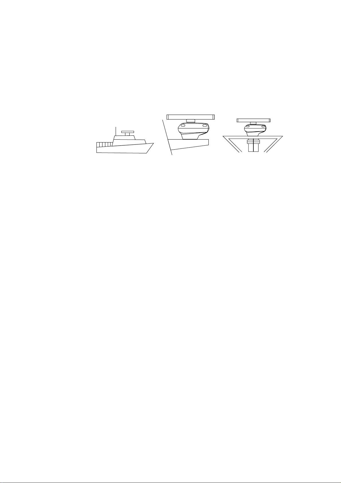
1.1 Antenna Unit
Mounting considerations
• The antenna unit is generally installed either on top of the wheelhouse or on
the radar mast, on a suitable platform. Locate the antenna unit where there is a
good all-round view.
(a) On bridge (b) Common mast (c) Radar mast
• No funnel, mast or derrick should be within the vertical beamwidth of the antenna in the bow direction, especially zero degrees ±5°, to prevent blind sectors and false echoes on the radar picture.
MOUNTING
Figure 1-1 Mounting methods
• It is rarely possible to place the antenna unit where a completely clear view in
all directions is available. Thus, you should determine the angular width and
relative bearing of any shadow sectors for their influence on the radar at the
first opportunity after fitting.
• Locate the antenna of a direction finder clear of the antenna unit to prevent
interference to the direction finder. A separation of more than two meters is
recommended.
• T o lessen the chance of picking up electrical interference, avoid where possible
routing the signal cable near other onboard electrical equipment. Also avoid
running the cable in parallel with power cables.
• A magnetic compass will be affected if placed too close to the antenna unit.
Observe the following compass safe distances to prevent deviation of a magnetic compass: Standard compass, 2.15 m, Steering compass, 1.60 m.
• Do not paint the radiator aperture, to ensure proper emission of the radar waves.
• The signal cable run between the antenna and the display unit is available in
lengths of 15 m (standard), 20 m, and 30 m. Whatever length is used it must be
unbroken; namely, no splicing allowed.
• The antenna base is made of cast aluminum. To prevent electrolytic corrosion
of the antenna base, use the seal washers and corrosion-proof rubber mat.
• Deposits and fumes from a funnel or other exhaust vent can adversely affect
the aerial performance and hot gases may distort the radiator portion. The antenna unit must not be mounted where the temperature is more than 70°C.
• Leave sufficient space around the unit for maintenance and servicing. See the
antenna unit outline drawing for recommended maintenance space.
1-1
Page 9
Assembling the antenna unit
The antenna unit consists of the antenna radiator and the antenna unit chassis,
and they are packed separately. Fasten the antenna radiator to the antenna unit
chassis as follows:
1. For the XN20AF, XN24AF, attach two guide pins to the underside of the an-
tenna radiator.
2. Remove the waveguide cap from the radiator bracket. The cap may be discarded.
3. Coat the waveguide flange with anticorrosive sealant as shown in Figure 1-2.
10 mm
Hole for
guide pin
5 mm
O-ring
Hole for
guide pin
Anticorrosive sealant
Figure 1-2 Coating the waveguide flange with anticorrosive sealant
4. Coat fixing holes for the antenna radiator with anticorrosive sealant.
5. Grease the O-ring and set it to the O-ring groove of the radiator flange.
6. Set the antenna radiator to the radiator bracket.
7. For the XN20AF, XH24AF, coat hex bolts (M8X40, slotted washer head, 8
pcs.) with anticorrosive sealant and use them to loosely fasten the antenna
radiator to the antenna unit chassis. For the XN12AF , coat hex bolts, flat washers and spring washers with anticorrosive sealant and use them to loosely fasten the antenna radiator to the antenna unit chassis.
8. For the XN20AF, XN24AF, remove two guide pins (inserted at step 1), and
then tighten fixing bolts.
CAUTION
Be sure to remove the guide pins.
Injury may result if the guide pins loosen
and fall.
1-2
Page 10
Antenna radiator
Waveguide
Radiator bracket
Guide pin
(XN20AF,
XN24AF
only)
O-ring
Hex bolt (M8X40), 8 pcs.
(XN20AF, XN24AF only)
Hex bolt (M8X35), 8 pcs.
Flat washer
Spring washer
(XN12AF only)
Figure 1-3 Fastening the radiator to the radiator bracket
Fastening the antenna unit to the mounting platform
The antenna unit may be assembled before hoisting it to the mounting platform.
However, do not hoist the antenna unit by the radiator. Always hoist the unit by its
housing. When using a crane or hoist, hoist the unit by the hoist rings which should
be fastened to the bolt fixing covers of the antenna housing.
CAUTION
DO NOT hoist the antenna unit by the
radiator; lift it by the hoist rings. (Be sure to
remove rings after hoisting the antenna unit.)
Hoist
ring
1. Construct a suitable mounting platform referring to the outline drawing at the
back of the manual.
2. Drill four mounting holes of 15 mm diameter and one cable entry hole of about
50 mm diameter in the mounting platform.
NO!
3. Lay the rubber mat (supplied) on the mounting platform.
1-3
Page 11
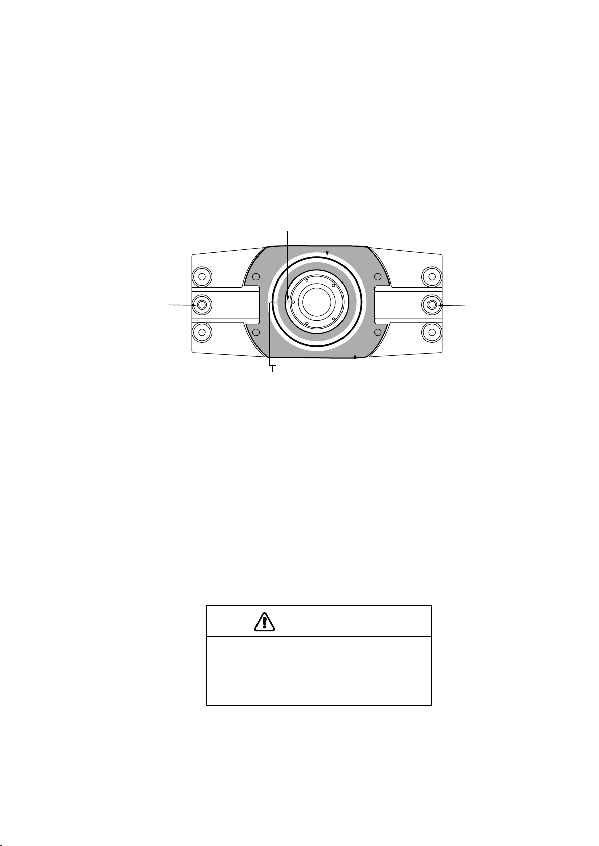
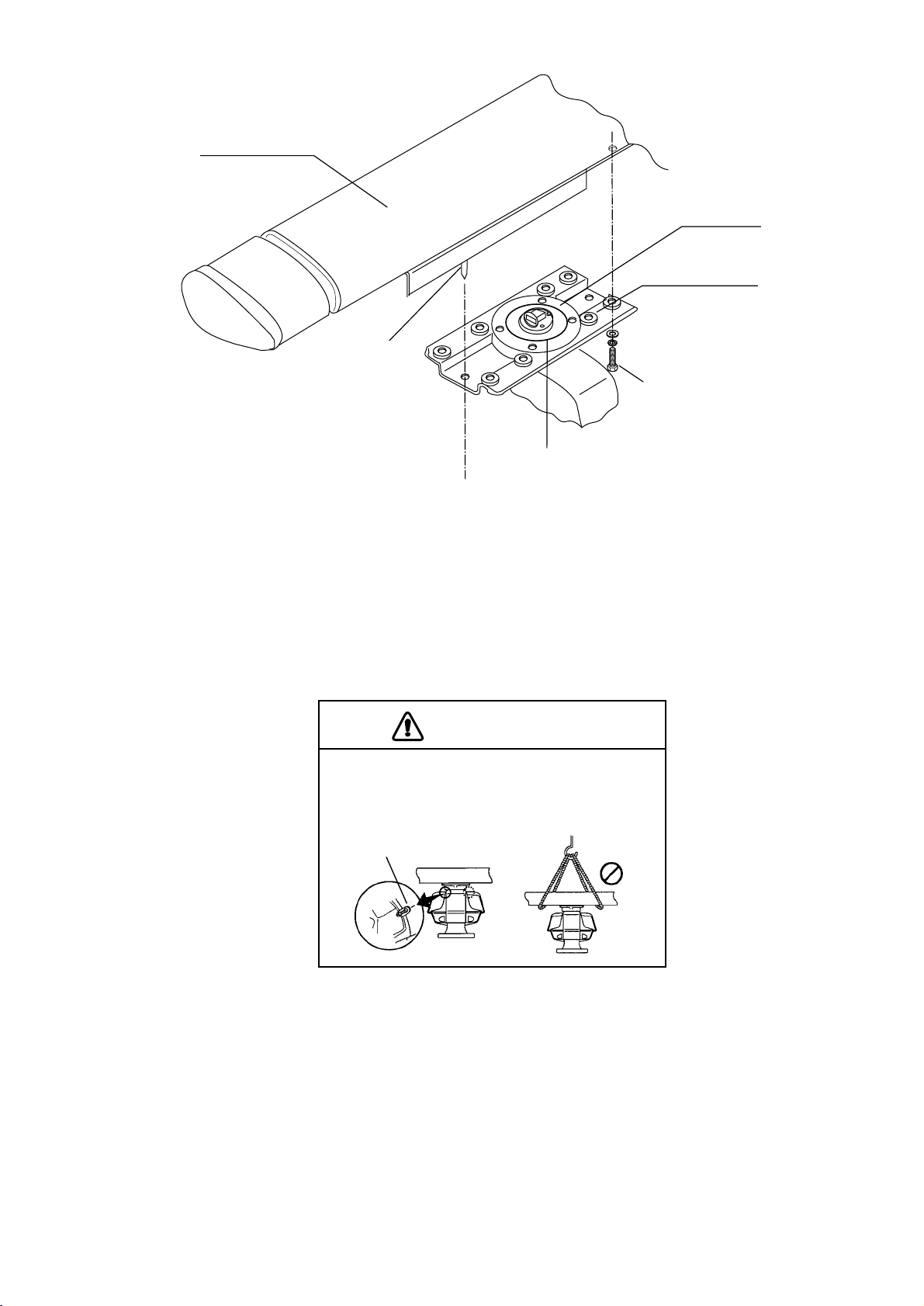
4. Place the antenna unit on the rubber mat orienting the unit so the bow mark on
its base is facing the ship’s bow.
Ground
terminal
Rubber
mat
Bow mark
Figure 1-4 Antenna unit, front view
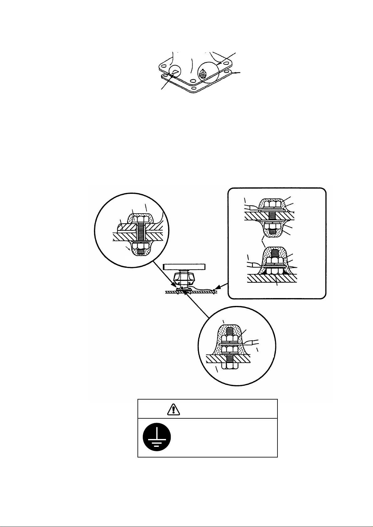
5. Fasten the antenna unit to the mounting platform with M12X60 hex bolts, nuts,
flat washers and seal washers.
6. Using hex bolt (M6X25), nut (M6) and flat washer (M6), establish the ground
system on the mounting platform as shown in Figure 1-5. Connect the ground
wire (RW-4747, 340 mm, supplied) between the grounding point and ground
terminal on the antenna unit. Coat the entire ground system with silicone sealant (supplied).
Anticorrosive sealant
Seal washer
Rubber mat
Anticorrosive
sealant
Ground wire
Anticorrosive
sealant
Ground wire
Anticorrosive sealant
Ground
terminal
Antenna base
Hex bolt
Spring washer
Spring washer
Hex nut
OR
Hex nut
Spring washer
Flat washer
Hex bolt welded to
ship's superstructure
Ground
wire
CAUTION
Ground the equipment to
prevent electrical shock
and mutual interference.
Figure 1-5 How to mount the antenna unit
1-4
Page 12
1.2 Display Unit
Before mounting the display unit
If Gyro Converter GC-8 (option) is to be used, install and setup the GYRO CONVERTER Board before mounting the display unit, because of the difficulty involved
in doing it after the display unit is installed. Instructions for installation and setup of
the board are in Chapter 4.
Mounting considerations
When selecting a mounting location, keep in mind the following points:
• Select a location where the display unit can be viewed and operated conveniently and where the screen can be viewed while facing towards the bow.
• Locate the unit out of direct sunlight and away from heat sources because of
heat that can build up inside the cabinet.
• Locate the equipment away from places subject to water splash and rain.
• The display unit is very heavy. Be sure the mounting location is strong enough
to support the weight of the unit under the continued vibration which is normally
experienced on the ship. If necessary reinforce the mounting location.
• Determine the mounting location considering the length of the signal cable between the antenna unit and the display unit. (The signal cable comes in lengths
of 15, 20 or 30 meters; maximum 100 meters).
• Leave sufficient space on the sides and rear of the unit to facilitate maintenance. Also, leave a foot or so of “service loop” in cables behind the unit so it
can be pulled forward for servicing or easy removal of connectors.
• A magnetic compass will be affected if placed too close to the display unit.
Observe the following compass safe distances to prevent deviation of a magnetic compass: Standard compass, 1.40 m, Steering compass, 1.05 m.
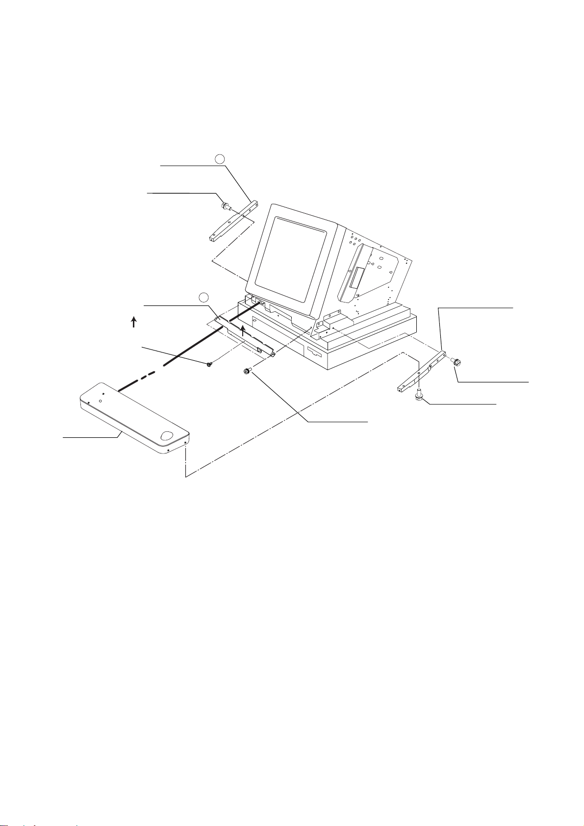
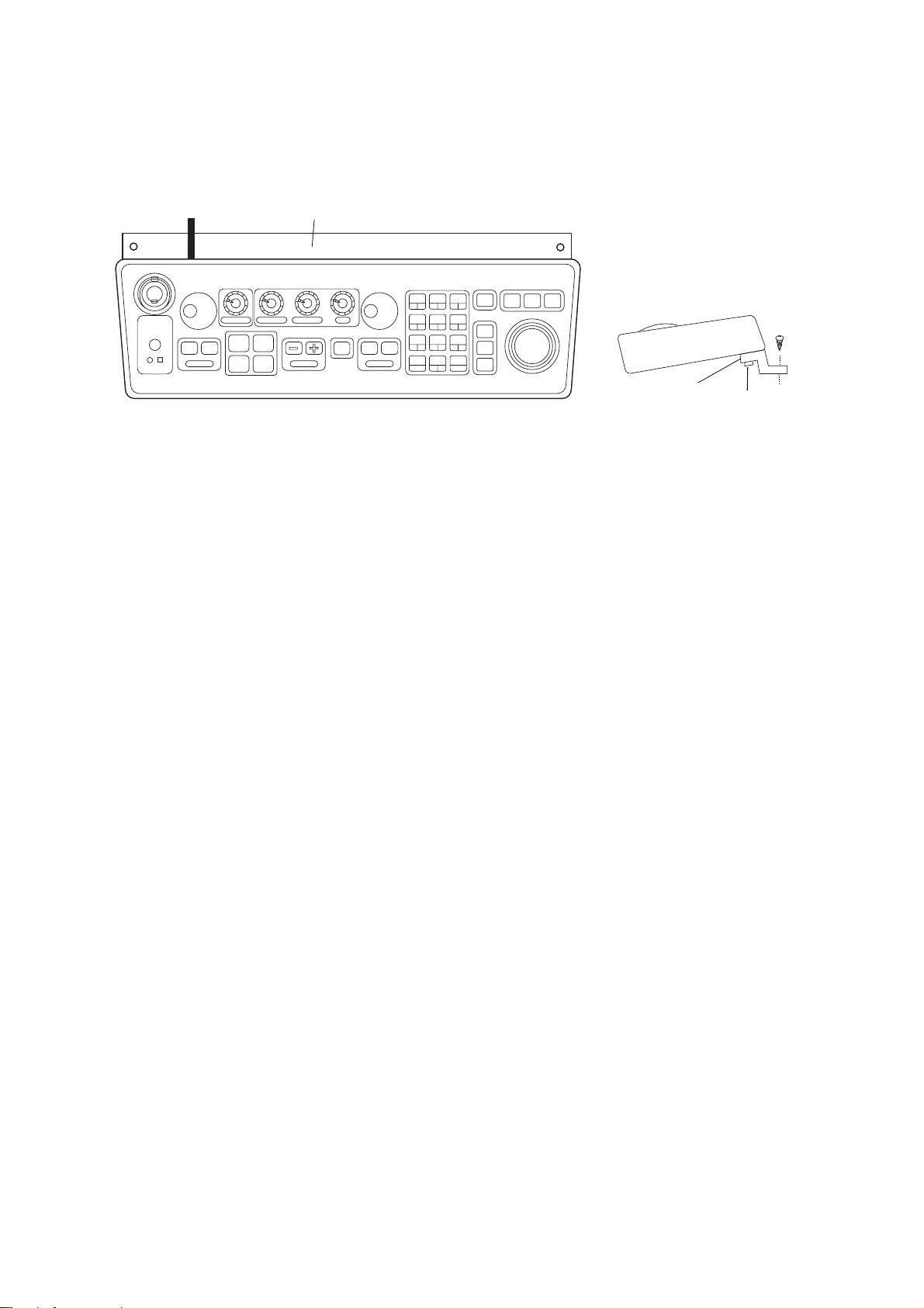
Mounting procedure
Control Head
Tabletop mounting
Two people are necessary to
complete this procedure.
1. Make four holes of 12 mm diameter in the mounting location
referring to the outline drawing
at end of this manual.
Left and right
arm covers
2. Unfasten the screws fixing the
right and left arm covers on the
control head.
3. Unfasten four M10 bolts hidden
by the arm covers.
M4X10
Figure 1-6 Control head
1-5
Page 13
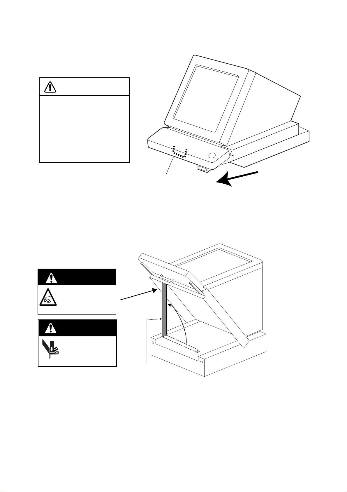
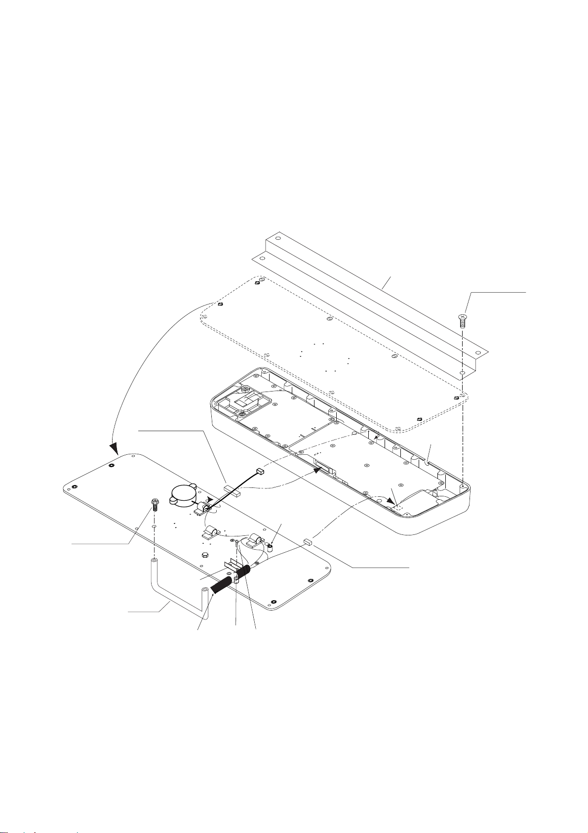
4. While one person is holding the mounting base at the sides, pull the handle on
the underside of the control head to draw the display unit toward you until you
hear a click.
CAUTION
Use two people to complete
this step.
The display unit may fall to
the deck when it is pulled
forward, since the mounting
base is not yet fastened to
the mounting location.
Handle
Pull
Figure 1-7 Display unit
5. This step requires two people to complete. While raising the monitor until the
CRT is horizontal, fix the stay as follows:
a)Raise the stay as shown below.
Two warning labels on
the underside of monitor
HORIZONTAL
WARNING
Possibility of injury.
Hold handle when
mounting display unit.
WARNING
Display unit may fall.
Lock stay before
servicing.
Stay
Figure 1-8 Display unit, inside view
1-6
Page 14
b)While pushing the stopper, set the catch on the display unit in the hole at the
front edge of the stay.
Stopper
Catch
Stay
Figure 1-9 Setting catch to hole in stay
c)Release hand from stopper.
Release stopper;
fix stay.
Figure 1-10 Stay fixed
6. Fasten the display unit to the mounting location at front fixing holes (2 points)
with M10 bolts, nuts and flat washers, using the pipe box spanner (supplied).
You cannot fasten the display unit at the rear fixing holes while the monitor is
raised.
7. Retract the stay and lower the monitor. Pull the monitor toward you by the
handle at the front of the display unit until you hear a click.
8. The rear left fixing hole is hidden under the PTU board cover. Remove the
cover as follows:
(1) Unfasten three M4X8 screws to remove the lead-in cover (V) which hides
the PTU section. Slide the cover to remove it.
REAR SIDE
Pan-head Screw
M4X8, 4 pcs.
Lead-in Cover (V)
Figure 1-11 How to remove the lead-in cover
1-7
Page 15
(2) Unfasten five M3X8 screws at the top of the PTU board cover and two
M4X8 screws at the front of the PTU cover. Slide the PTU board cover
forward.
Fixing hole (rear)
*Screw
(M3X8, 5 pcs.)
Slide forward
J106
J105
J104
J103
*
Knob
Screw (M4X8, 2 pcs.)
Fixing hole (front)
J446
J466
J462
J465
*
*
*
Figure 1-12 How to dismount the PTU cover
(3) Remove the cover by grasping the knob on the top of the cover.
10.Use M10 bolts, nuts and flat washers to fix the display unit at the rear mounting
holes, using the pipe box spanner (supplied).
11.Close the PTU board cover.
12.Push the monitor forward until you hear a click.
13.Refasten the bolts removed at step 3.
14. Fasten the left and right arm covers with M4X10 screws.
Console type mounting
1. Make six holes of 15 mm diameter and a cable entrance hole through the deck
referring to the outline drawing at end of this manual.
2. Open the front cover.
3. Fix the equipment by using M12 bolts, nuts and washers.
4. Hoist the console to the deck by using the eye bolts attached to the console.
Remove the eye bolts and set the cosmetic caps (w/washers) to the eye bolt
holes.
1-8
Page 16
Separating the control head
The control head connects to the display unit with a connection cable, thus it can
be located where desired, using the separate control head kit (option).
Separate type control head kit (Type: OP03-157, Code No.: 008-500-630)
emaNepyTytQ.oNedoCskrameR
.yssAelbaCP1/P02BS4642LU1218-041-0002249S30,m01
teeFrebbuRpilsnoN3005-JS4787-108-000epatdedis-elbuodhtiW
)V(revoCtnorFrotinoM1371-441-301065-472-001
etalPgnixiFBK1961-441-301049-362-001
)V(etalPeldnaH2371-441-301075-472-001eldnahgnixifroF
BKrevoCtsuD3961-441-301067-172-001
wercStespU403SUS01X5M2882-208-000
wercSgnidniB0072C8X4M2704-608-000
Display unit modification procedure
1. Raise the monitor unit and fix it with the stay. Refer to procedure for tabletop
mounting on page 1-5.
2. Inside the display pedestal, unplug two connectors from the control head cable
(P412 from MOTHER Board and J583) and unfasten two earth wires.
PTU COVER
Control Head
Cable
P412
J583
J418
Earth Wire
MB 03P9251
INT
03P9252
Figure 1-12 Display unit, inside view
1-9
Page 17
3. Retract the stay to lower the monitor.
4. Unfasten eight binding screws (M4X8) to dismount the top cover 1, right cover
2 and left cover 3.
5. Loosen three screws (M4X10) fixing the left maintenance cover (4). Slide the
cover to dismount it.
6. Loosen four screws (M4X10) fixing the lead-in cover (5) at the rear of the
display pedestal. Slide the cover to dismount it.
Top Cover (1)
Binding Screw
M4X8, 2 pcs.
Left Cover (3)
Push in direction
of arrow
Pan-head Screw
M4X10, 3 pcs.
Touching inside
of CRT panel
A
Left Maintenance Cover (4)
A EXPLODED VIEW
Binding Screw
M4X8, 4 pcs.
Lead-in Cover (5)
Pan-head Screw
M4X10, 4 pcs.
Push in
direction of
arrow.
(Do same on
other side.)
Left Cover (2)
Binding Screw
M4X8, 2 pcs.
Figure 1-13 How to dismount covers
7. At the left side of the monitor, unfasten the clamp which fixes the control head
cable.
8. At the rear of the display pedestal, fasten the clamp which fixes the control
head cable.
1-10
Page 18
Monitor
Control Head Cable
J582
J581
Remove clamp from rear side
Remove clamp
from left side
Figure 1-14 Clamp position
11.Unfasten four upset screws (6) at the bottom of the right and left KB arms to
dismount the control head.
12.Unfasten three screws (M4X10) and two screws (M4X8) to remove the right
lower cover (7) and the left lower cover (8).
Pan-head Screw (M4X10, 3 pcs., upper)
Binding Screw (M4X8, 2 pcs., lower)
Clamp
Left Lower Cover (8)
Control Head
Upset Screw (6)
(M5X25, 4 pcs.,
including those on
opposite side)
Right KB Arm
Right Lower Cover (7)
Pan-head Screw (M4X10, 3 pcs., upper)
Binding Screw (M4X8, 2 pcs., lower)
Figure 1-15 Display unit, front view
1-11
Page 19
13.Unfasten three screws (M5X25) to remove the right KB arm (9) and the left KB
arm (q0).
14.Unfasten one screw (M4X10), two screws (M5X12) to dismount the panel cover
(q1).
15.Fasten the two upset screws (M5X12) unfastened at step 14 at the front bottom
of the control head.
Left KB Arm (11)
Screw
M5X25, 3 pcs.
Pan-head Screw
M4X10
Control Head
Panel Cover (10)
Push up
to fix
Figure 1-15 Detaching the control head
Screw
M5X12, 2 pcs.
Right KB Arm (9)
Screw
M5X25, 3 pcs.
Screw
M5X25 (4 pcs.,
incl. those on
opposite side)
1-12
Page 20
Control head modification procedure
1. Unfasten eight screws (M4X8) on the underside of the control head. Unplug
connectors P314, P312 and P317 from the control head. Separate the KB bottom plate from the control head.
2. Unfasten the screw (M4) fixing the ground terminal and two screws (M4X8)
fixing the clamp. Remove the connection cable assy.
3. Unfasten two screws (M6X12) from the inside of the bottom plate of the control
head to dismount the handle.
4. Replace the cable assy. with cable assy. UL2464SB2-0P/1P (10 m, supplied)
as below and reassemble the control head.
KB Fixing Plate
Screw
M4X8 (8 pcs.)
P312 FX Connector
KB BOTTOM
PLATE
Upset Screw
M6X12 (2 pcs.)
Handle
KB Clamp
Replace with
cable assy. in
kit.
J314 (underside)
J312 (underside)
Earth Wire
Spacer
Pan-head Screw M4X8 (2 pcs.)
Be careful not to pinch cable between
KB clamp and spacer.
Figure 1-16 Control head
J317 (underside)
P314 XH3P
Lay cable in slot.
1-13
Page 21
Wiring between display unit and control head
1. Fasten the handle to the supplied handle plate (V), using the screws formerly
used to fixed the handle.
2. Using two upset screws (M5X10, supplied), fasten the handle plate (V) to the
location shown in Figure 1-17.
Handle Plate (V)
DOWN
Handle
Upset Screw
2 pcs.
Insert handle
plate (V) here.
Figure 1-17 Attaching the handle plate (V)
3. Pull the monitor forward.
4. Lead in the control head cable through the cable clamp at the rear of the display unit. See pages 2-9 and 2-10 for location of cable clamp.
5. Raise the monitor and fix it with the stay. (See page 1-5 for instructions.) Inside
the display unit, plug in two connectors and fasten two ground wires. See Figure 1-12 for location.
6. Retract the stay to lower the monitor.
7. Fasten two bolts (M10) at the front of the display unit. For location see step 3 on
page 1-5.
8. Attach the monitor cover (supplied) to the handle plate with two M4X8 binding
screws (supplied).
9. Attach right and left lower covers, left maintenance cover , right and left covers,
lead-in cover, top cover, and right and left arm covers in that order.
1-14
Page 22
10.Attach rubber to feet to the bottom of the keyboard if the keyboard is not going
to be permanently fixed. To fix the keyboard to a desired location, fasten the KB
fixing plate to the keyboard and desired location with two upset screws (M5X25,
formerly used to fasten KB arms) and two tapping screws (φ6.5, local supply)
as below.
KB Fixing Plate
CONTROL HEAD TOP VIEW
Figure 1-18 How to attach KB fixing plate
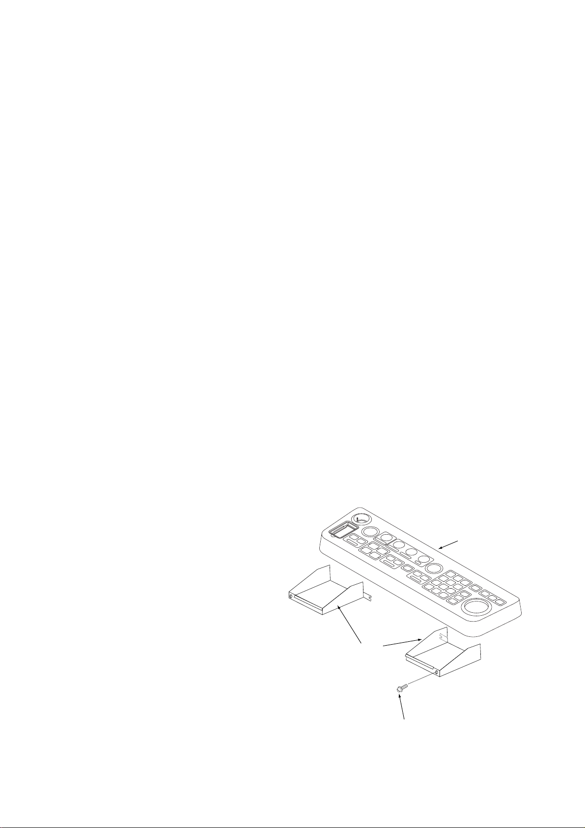
11.Set dust cover KB (supplied) on the control head.
CONTROL HEAD
SIDE VIEW
KB Fixing
Plate
φ6.5
Tapping
Screw
M5X25
Upset
Screw
1-15
Page 23
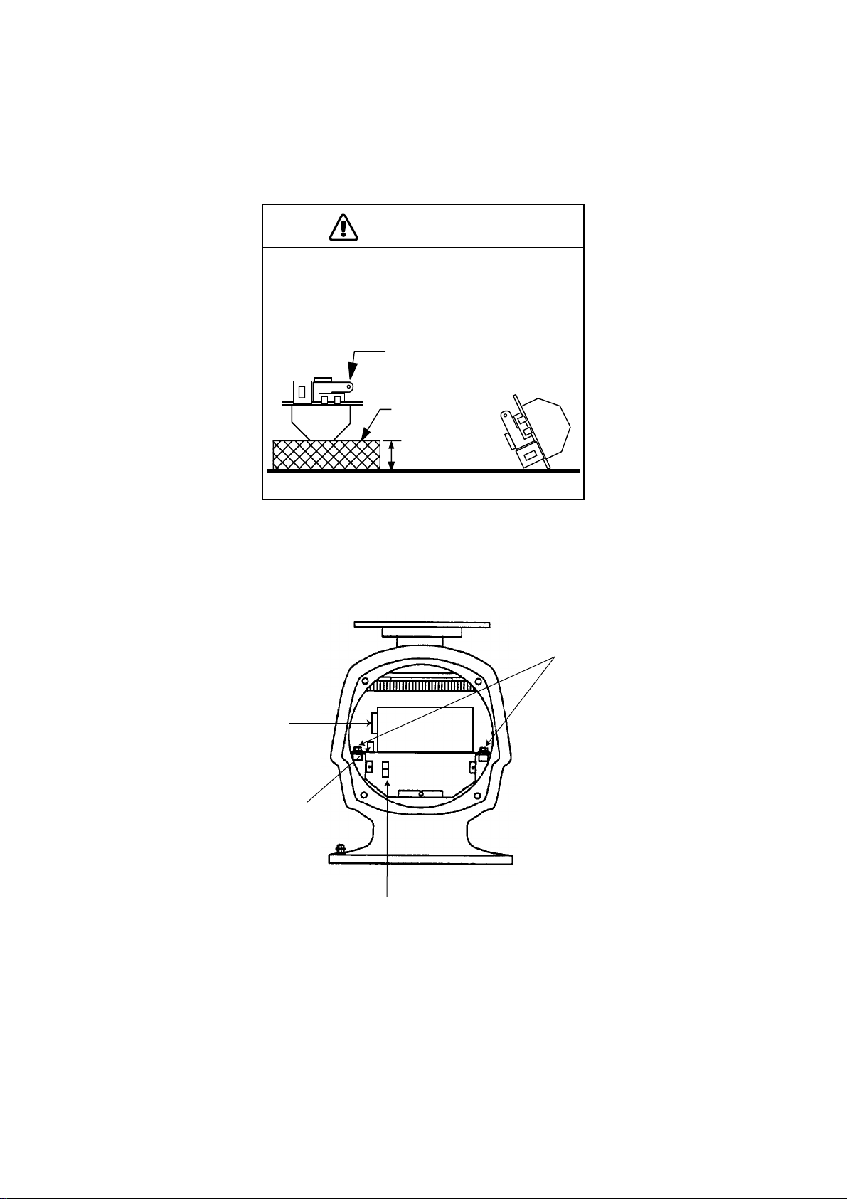
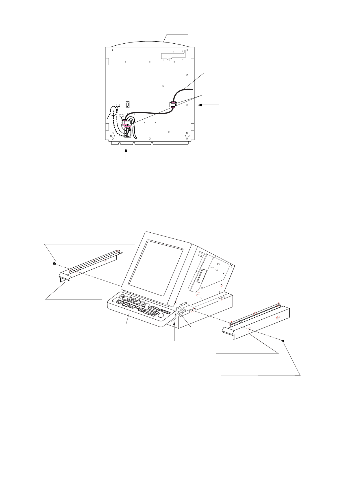
2.1 Antenna Unit
The magnetron in the transceiver module will demagnetize if it contacts ferrous material. When
dismounting the transceiver module, lay it on its
side or on top of non-ferrous material as shown
below.
WIRING
CAUTION
Transceiver module
(magnetron inside)
Non-ferrous
block
Height more
than 5 cm
1. Open the antenna unit cover.
2. Disconnect plugs P611, P801 and P821.
3. Unfasten the transceiver module (two bolts). Remove the transceiver module.
Fixing
bolts
J611
J801
J821
Figure 2-1 Antenna unit, front view
2-1
Page 24
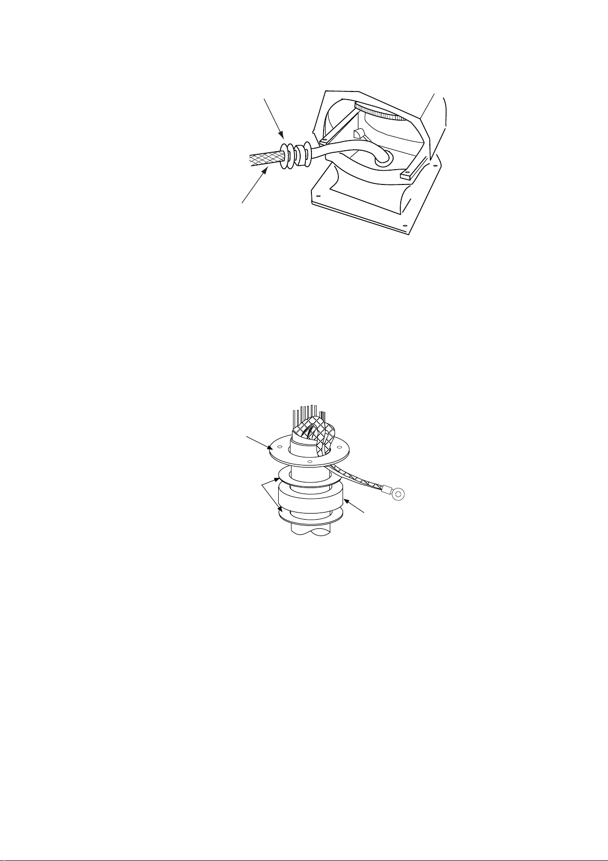
4. Unfasten the four fixing bolts on the cable gland at the base of the antenna unit.
Remove clamping ring, rubber gasket and washers.
From left: Clamping ring,
washer, rubber gasket
and washer
Signal cable
Figure 2-2 Antenna unit, front view, cover removed
5. Pass the signal cable through the cable entry hole in the antenna unit mounting
platform. Trim the cable so about 80 cm of it protrudes past the cable gland.
6. Slide the clamping ring, washer, rubber gasket and washer onto the cable in
that order.
7. Fabricate the signal cable as shown on page 2-4.
8. Referring to Figure 2-3, pass the outer and inner shields between the signal
cable and the clamping ring. Fasten the cable gland.
Clamping
ring
Washers
Rubber
gasket
Figure 2-3 Passing cable shields between cable and clamping ring
9. Connect the signal cable to the terminal board RTB801 by referring to the interconnection diagram. Leave “slack” in the coaxial wire to prevent breakage.
10.Bind cores of cables with cable ties.
11.Mount the transceiver module. Connect plugs P611, P801 and P821. Fasten
shield to ground terminal in the transceiver module.
2-2
Page 25
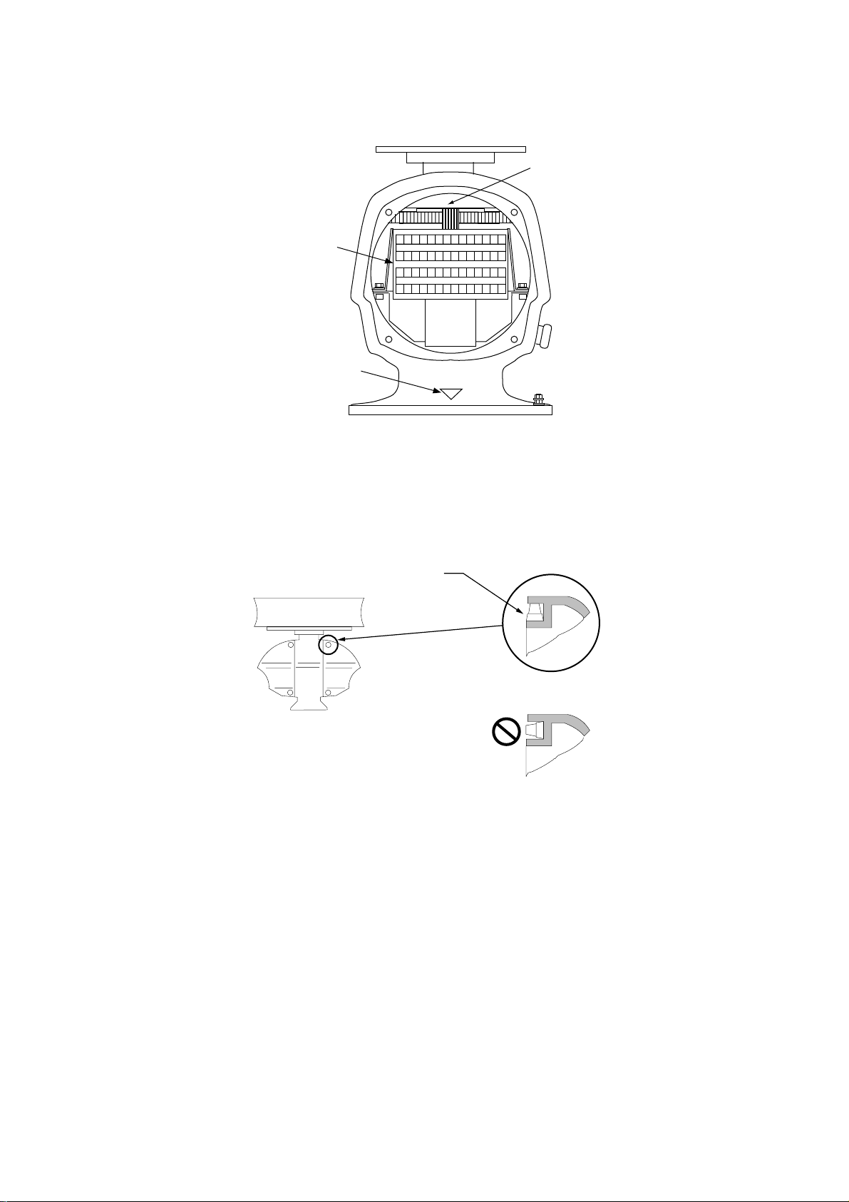
12.If the antenna unit is mounted 2° or more left of ship’s bow, adjust the position
of S901 so it becomes “on” (contact between #1 and #2 on pcb MP-3795). To
access S901, open the bow side cover; S901 is above the drive gear.
S901
RTB801
Bow mark
1 2 345 67891011121314
15 16171819 20 212223 24 25 26 2728
Figure 2-4 Antenna unit, front view
13.Confirm that all screws are tightened and all wiring is properly made. Coat
waterproofing gasket, bolts and tapping holes of antenna unit with silicone
grease. Check that the waterproofing gasket is seated as shown in Figure 2-5.
Close the antenna unit cover.
Coat gasket with silicone grease.
DO NOT use silicone sealant.
CORRECT
WRONG
Figure 2-5 Correct seating of waterproofing gasket
2-3
Page 26
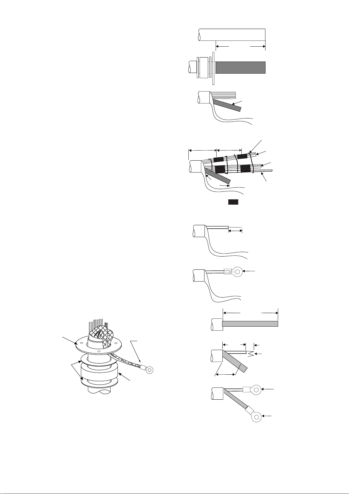
Fabricating signal cable S03-75
VINYL SHEATH
1. Remove the vinyl sheath by 450 mm.
2. Slide the clamping ring, washer, rubber gasket and washer onto the signal cable in that
order.
3. Unravel the outer shield to expose the cores
in the outer layer. Then, unravel the inner
shield to expose the cores in the inner layer.
Label all inner cores to aid in identification.
4. Attach EMI cores to all inner cores and all
outer cores, and tie cables with cable ties.
Note: There are two types of EMI cores, thick
and thin.
5. Trim each core (except coaxial wire) considering its location on the terminal board.
6. Trim the inner and outer shields leaving 500
mm each. Twist shields together and attach
crimp-on lug FV5.5-4 (Blue, ø4).
7. Remove insulation of each core by about 6
mm. Fix crimp-on lug FV1.25-M3 (Red, ø3)
to each core.
8. Fabricate the coaxial cable. Make the length
10 mm longer than the shield to prevent wire
strain. Attach crimp-on lug FVD1.25-3 (Red,
ø3) to coaxial cable.
Less than
100 mm
500mm
450 mm
70-130 mm
6 mm
Inner shield
Cable tie
Outer cores
Inner cores
Coax cable
= EMI cores
Outer cores: (RFC-13) thick
Inner cores: (RFC-10) thin
Crimp-on lug
(FV1.25-M3,
Red, φ3)
Clamping
ring
Washers
Crimp-on lug
(FV5.5-5, Blue, φ4)
Rubber
gasket
Figure 2-7 How to ground
signal cable S03-75
2-4
2C-2V
75 mm
50 mm
45 mm
Cut here
6 mm
Fold four times
Crimp-on lug
(FVD1.25-3,
Red, φ3)
Crimp-on lug
(FV1.25-3,
Red, φ3)
Figure 2-6 How to fabricate
signal cable S03-75
Page 27

2.2 Display Unit
Two cables are terminated at the display unit: the signal cable S03-75 and the
power cable. The signal cable comes with a connector preattached to it for connection to the display unit. Fabricate the power cable as shown on the next page.
The display unit designed to run on AC
power has a power switch inside its
base which cuts off 100/200 VAC power
to the display unit. Pull the display unit
forward several centimeters to access
the switch. TURN THE SWITCH OFF
(as well as the main POWER switch)
WHENEVER ACCESSING INSIDE THE
DISPLAY UNIT.
POWER Switch in AC
Powered Display Unit
POWER Switch
J106
J105
J104
J103
J446
J466
J462
J465
Display unit, inside view
2-5
Page 28
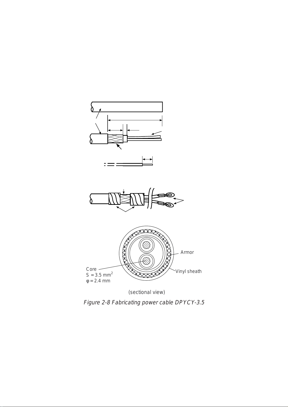
Fabricating the AC power cable (supplied)
1. Remove the vinyl sheath by 80 mm.
2. Cut off jute tape wrapped around the armor.
3. Unravel the armor to expose the cores by about 35 mm.
4. Remove insulation of cores by about 10 mm. Fix crimp-on lugs type FV5.5-4 to
the cores.
5. Cover the armor with vinyl tape, leaving the portion which will lie inside the
cable clamp untaped.
(a)
Vinyl sheath
(b)
(c)
(d)
DPYCY-3.5
Approx. 80 mm
40 mm
Clamp here.
5 mm
Armor
Taping
Core
10 mm
Crimp-on lug
FV5.5-4
Armor
Core
S = 3.5 mm
φ = 2.4 mm
2
(sectional view)
Vinyl sheath
Figure 2-8 Fabricating power cable DPYCY-3.5
2-6
Page 29
Fabricating the DC power cable (CVV-S 8X2C, option)
1. Remove the vinyl sheath by 100 mm.
2. Unravel the braided shield 60 mm from end of cable.
3. Remove the jute tape and inclusion from cable.
4. Expose the cores by 50 mm.
5. Expose the shield by 60 mm. Tape 10 mm of the shield tip.
6. Remove the sheath of cores by 10 mm. Attach crimp-on lugs type 8NK4 to the
cores and crimp-on lug type FV5.5-4 (yellow) to the shield.
7. Tape the cable as shown in the figure below. Fasten the shield to screw (M4) on
the cable clamp.
100 mm
CVV-S 8X2C
Braided Shield
Taping
Fasten cable
clamp here.
Taping
60 mm
Core
Jute Tape
Inclusion
50 mm
10 mm
60 mm
Crimp-on Lug
8NK4
Crimp-on Lug
FV5.5-4
Figure 2-9 Fabricating power cable CVV-S 8X2C
2-7
Page 30

Leading cables into the display unit
The cable clamp may be positioned within the display unit (default arrangement),
outside the display unit or at the bottom of the display unit (when using console
mount, for example). When the cable clamp is located outside or beneath the display unit, use the bottom clamp front plate and bottom clamp rear plate (supplied
with installation materials).
Also, use the shielding foam (supplied) to guard against noise.
Cable fed from rear of display unit (Default method)
Nav equipment
(Gyrocompass)
Keyboard
Log
PWR
Cable position in clamp
(Display unit, rear view)
ANT
Slave display
Navigation
External CRT
Hex bolt
M5X12 SUS,
2 pcs
Hex bolt
M5X35 SUS,
2 pcs
Hex bolt
M5X35 SUS,
2 pcs
Pan-head screw
M4X8
(D) Rear clamp
plate
(C) Signal clamp
(Aluminum)
(B) Power clamp
(Aluminum)
(D) Rear clamp plate
(C) Signal cable
(Aluminum)
(B) Power clamp
(Aluminum)
(A) Rear clamp base
(Display unit, right-hand side view)
Figure 2-10 Default cable clamp position
• Place shielding foam between cables, and then attach foam to aluminum clamps.
• Fill unused clamp holes with shielding foam.
(Construction of
cable clamp)
Make sure foam contacts rear chassis.
Rear cable entrance
Cable
Shielding foam
(Display unit, rear view)
(A) Rear clamp
base
2-8
Page 31

Cable fed from outside display unit
Shielding foam
(D) Rear clamp plate
(C) Signal clamp
(Aluminum)
(B) Power clamp
(A) Rear clamp base
M5X10 (2 pcs)
(Installation materials)
Bottom clamp front plate
(Installation materials)
(Aluminum)
Rear cable entrance
Figure 2-11 Clamp position outside display unit (display unit right side view)
• Place shielding foam between cables inside of display unit, and then attach
foam to chassis.
• Fill unused clamp holes with shielding foam.
Cables fed from bottom of display unit (for console mount)
Lead in cables through the cable clamp at the rear of the console and ground their
shields in the cable clamp. For signal cable, remove vinyl sheath where cable lies
in cable clamp. Fasten cables with cable ties.
Seventh hole
from the top
Power Cable
(For display unit)
Close shutter door and cover
Close shutter and cover
with aluminum tape to
it with aluminum tape to keep
keep foreign objects out
foreign objects out of the
of the display unit.
display unit.
Performance
Monitor
Cable Arrangement in the Console (Top view)
SIGNAL CABLE:
Remove the vinyl sheath here.
(1300 mm from display unit end
of cable remove sheath by 70 mm.)
Gyrocompass
Power Cable
(For PM)
Log
NAV
Signal Cable
ARPA
Slave Display
Figure 2-12 Clamp position at bottom of display unit
2-9
Page 32

Connections
Raise the monitor and fix it with the stay. (For procedure see page 1-5.) Remove
the shield cover from the INT Board. Connect signal, power, gyro and log cables
as shown below. Optional equipment are connected to the INT Board. Be sure to
ground the display unit.
PTU BOARD
03P9245
MOTHER BOARD
03P9251
J448
Antenna
Unit
Fasten shield here.
(Tabletop type)
Connect coax
cable here.
DJ1
J5
J4
Gyro
Log
Ship’s
mains
Ground terminal
(Tabletop type)
Fasten shields
together here.
(Console type)
Terminal
board
POWER switch (AC only)
(Turn off before accessing
inside the display unit.)
Signal cable should
1
touch edge of
partition board.
Fasten TX-HV
line to #1 terminal.
To fasten;
1. Unfasten screws.
2. Slide terminal forward.
3. Lift terminal to remove it.
J442
J443
J444
J463
J457
J458
J453
J451
J452
INT BOARD
03P9252
J450
J454
J455
J466
J462
J456
GYRO CONVERTER
BOARD 64P1106
Fix the DJ1 connector with
two M3X8 screws (supplied).
J445
Location of connectors
on the INT Board. See
next page for connector
J448
J446
J467
J449
J465
description.
Bind the cables so as not to pinch them
between the monitor and mounting base.
Take special care with the high voltage
line.
M4X8 (2 pcs.)
CAUTION
Ground the equipment to
prevent electrical shock
and mutual interference.
3
2
1
2
3
4
5
6
7
8
Figure 2-13 Display unit, inside view
2-10
Page 33

Connectors on the INT Board
Table 2-1 Connectors on the INT Board
emanlangiSnoemaN
bcp
langiStupnI
langisoryG4Jnip3,HVbcpnO:*
goldeepS
langis
youbradaR
langis
etomeR
lanretxE
APRA
langis
langis
GOL844Jnip3,HN .cte,mn/seslup002
RADAR
YOUB
RADAR-TXE
langisyalpsid
langiStuptuO
yalpsidevalS
7-JRro
APRA-TXE444Jnip8,HN,gniraeb,gnidaeH
EVALS244J
.on
5Jnip5,HV
rotcennoC
544Jnip4,HN
854Jnip8,HN
344J
rotcennoC
epyt
nip8,HN,141-DC,041-DC
elbacilppA
tnempiuqe
,005-DG
,2KM005-DG
,008-DMF
08-DMF11*0
skrameR
)noitpo(6011P46A
reggirtxT
,gniraeb,gnidaeH
reggirtxT,oediv
roftinuyalpsiD:1*
ebnacV5212-RF
evalssadesu
.tinuyalpsid
langisrezzuBZUB-TXE154Jnip9,HNpma/wrekaepSlangisrekaepS
langisrotinoM944Jnip01,HN,suonorhcnysREV
,suonorhcnysROH
oediv
)tamrofCSTN(
C232-SRC232-SR654Jnip4,HX
golanAGOLANA354Jnip3,HNlangisTOR
lanretxE
rezzub
atadSNIATAD.SNI554Jnip5,HN
7-JR7-JR754Jnip51,HN
8-JR8-JR614Jnip4,HNdraoBrehtoMnO
atadvaNATADVAN054Jnip5,HN
atadAPRAATADAPRA454Jnip5,HN
MRALATXE
)CA(
langiStuptuO/tupnI
254Jnip3,HN
1529P30
FFO_NO_MPTNIRP_MP114Jnip3,HXdraoBrehtoMnO
1529P30
Note: How to attach NH connector is shown on the next page.
2-11
Page 34

How to attach NH connector
HOW TO ATTACH NH CONNECTOR TO SIGNAL CABLE
NH connector wire
NH connector
housing
1
Insert NH connector
wire into NH connector
housing.
Shrink tubing
20mm
2
Cut shrink tubing
in 20 mm lengths and
slip onto each wire.
Solder
3 Solder connector
to signal cable.
Figure 2-14 How to attach NH connector
2.3 Changing AC Power Specification
For 100 V AC or 220 V AC power , add or delete jumper wires on the PTU Board and
change the power fuses inside the display unit as shown in the table below according to ship’s mains. The figure below shows the location of the power fuses and the
jumper wires on the PTU Board.
4
Heat shrink
tubing with soldering iron.
Table 2-2 Jumper wire setting on the PTU board, fuse rating and power specification
BCP.cepSrewoP
annetnA
mpr
1PJ2PJ3PJ4PJ19PJ29PJ
A5429P30CAV511/011/001mpr42SEYSEYSEYONONON
C5429P30CAV511/011/001mpr24SEYSEYSEYONSEYSEY
D5429P30CAV032/022mpr42ONONONSEYONON
F5429P30CAV032/022mpr24ONONONSEYSEYSEY
Jumper wire to use:
JP1: 0.8 dia. gilded wire
JP2, JP3, JP4, JP91, JP92: type ERD-S2TCOV
03P9245
C11
C12
Fuse
JP1
JP2
T21
T1
JP92
JP3
JP4
U92
JP91
rewoP
sesuF
A01
A5
PTU Board
Figure 2-15 Display unit, inside view
2-12
Page 35

INITIALIZATION AND ADJUSTMENT
3
.1 Tuning Initialization
Tune the radar as follows: Press [RADAR MENU] [0] [0] [2] [0] [0] [0] (TUNE
INITIALIZE on the RADAR 3 menu) and press the [ENTER] key.
3.2 Accessing Menus for Initialization and Adjustment
To access them do the following:
1. T urn on the power.
2. Press the [RADAR MENU] key five times while pressing and holding down
the [HL OFF] key. A beep sounds to confirm operation.
Restoring default settings
1. Press [RADAR MENU] [0] [0] [0] [2] [0] [0] [0] to display the INITIAL SETTING
4 menu.
2. Press the [0] key to select FACTORY DEFAULT.
3. Press the [ENTER] key five times, and turn the power off and on again.
4. "Initializing" appears during restoring. It takes about 90 seconds to restore the
default settings, after which the normal display appears.
3.3 Adjusting Video Signal Level
When the signal cable is very long, the video amplifier input level decreases,
shrinking target echoes. To prevent this, confirm (and adjust if necessary) video
amplifier input level.
1. Connect an oscilloscope to TP6 on the INT Board (03P9252) in the display
unit.
2. Transmit on the 12 nm range.
3. Adjust R21 on the INT Board so the value of TP6 is 4 Vpp. (For remote display, adjust R134 on the INT Board.)
TP1
R134
R21
INT Board
(03P9252)
Figure 3-1 Display pedestal
3-1
TP6
Page 36

3.4 Heading Alignment
You have mounted the antenna unit facing straight ahead in the direction of the
bow. Therefore, a small but conspicuous target dead ahead visually should appear on the heading line (zero degrees).
In practice, you will probably observe some small bearing error on the display
because of the difficulty in achieving accurate initial positioning of the antenna
unit. The following adjustment will compensate for this error.
Correct bearing
relative to heading
Target
a
270
Antenna mounted
error to port
(HDG SW advanced)
000
010
350
020
340
330
320
310
300
290
280
260
250
240
230
220
210
200
030
040
140
150
160
190
170
180
Picture appears
deviated clockwise.
a
050
060
070
080
090
100
110
120
130
Apparent
position
of target
Antenna mounted
error to starboard
(HDG SW delayed)
Apparent position
of target
Target
b
b
000
010
350
020
340
330
320
310
300
290
280
270
260
250
240
230
220
210
200
030
040
050
060
070
080
090
Correct
100
110
bearing
120
130
relative to
140
150
160
190
170
180
heading
Picture appears
deviated counterclockwise.
Figure 3-2 Heading alignment
1. Press [RADAR MENU] [0] [0] [0] [2] [2] to select HL ALIGN on the INITIAL
SETTING1 menu.
2. Select a target echo (by gyrocompass, for example) at a range between 0.125
and 0.25 nm, preferably near the heading line.
3. Operate the EBL control to bisect the target echo with the heading line. (The
value shown on the display is antenna position in relation to ship's bow.)
4. Press the [ENTER] key to finish.
3-2
Page 37

3.5 Adjusting Sweep Timing
Sweep timing differs with respect to the length of the signal cable between the
antenna unit and the display unit. Adjust sweep timing at installation to prevent
the following symptoms:
• The echo of a "straight" target (for example, pier), on the 0.25 nm range, will
appear on the display as being pulled inward or pushed outward. See Figure
3-3.
• The range of target echoes will also be incorrectly shown.
(1) Correct
Figure 3-3 Examples of correct and incorrect sweep timings
1. Press [RADAR MENU] [0] [0] [0] [2] [3] to select TIMING ADJ on the INITIAL
SETTING1 menu.
2. Transmit on the 0.25 nm range.
3. Adjust radar picture controls to display picture properly.
4. Select a target echo which should be displayed straightly.
5. Adjust the VRM control to straighten the target echo.
6. Press the [ENTER] key.
(2) Target pushed
inward
3.6 Suppressing Main Bang
If main bang appears at the screen center, suppress it as follows.
1. Transmit on a long range about ten minutes.
(3) Target pushed
outward
2. Adjust the [GAIN] control to show a slight amount of noise on the display.
3. Select the 0.25 nm range. Adjust the [A/C SEA] control to suppress sea clutter.
4. Press [RADAR MENU] [0] [0] [0] [2] to open the INITIAL SETTING1 menu.
5. Press the [7] key to select 7. MBS.
6. Adjust the VRM control to adjust timing; the EBL control to adjust level.
7. Press the [ENTER] key.
3-3
Page 38

3.7 Confirming Magnetron Heater Voltage
PM
ON
OFF
TUNE
DEGAUSS ERROR
ANTENNA
switch
ANTENNA
Magnetron heater voltage is adjusted at the factory. However, confirm that it is
within the prescribed rating.
Table 3-1 Magnetron heater voltage rating
gnitaR)Wk52(V5212-RF
mn521.0,YB-TSV4.8-V2.8
egnarxam,XTV5.7-V5.6
1. Press [RADAR MENU] [0] [0] [0] [2] [0] to open the INITIAL SETTING2 menu.
2. Press [5] to select the 5. SCANNER STOPPED field and the TX option.
3. Disconnect connector P821 from the antenna unit.
4. Turn off the ANTENNA switch in the tuning compartment in the display unit.
Figure 3-4 Antenna switch in tuning compartment
5. Turn off screen brilliance.
6. Measure voltage between pins #12(+) and #5(-) on connector P801 on the
RFC Board (03P9243) in the antenna unit.
7. If the voltage is not within the rating shown in Table 3-1, adjust potentiometer
VR1 on the RFC Board.
J611
03P9243
J801
VR1
J821
Figure 3-5 RFC Board
8. Set 5. SCANNER STOPPED on the INITIAL SETTING2 menu to ST-BY.
3-4
Page 39

3.8 Initial Setting Menus
The INITIAL SETTING menus (four menus) and the OWN SHIP INFORMA TION
menu setup the radar according to expected usage, authorities specification, ship's
characteristics, operator's preference, etc. Set items on each menu in accordance with regulations/operator's preference. After entering initial settings, reset
the power.
Press [RADAR MENU] [0] [0] [0] [2]
[OWN SHIP INFORMATION]
1 [INITIAL SETTING(1)]
2 SHIP'S LENGTH 000m
3 SHIP'S WIDTH 00m
4 RADAR POSN FOR BOW 000m
FOR PORT 00m
5 NAV ANT POSN FOR BOW 000m
FOR PORT 00m
6 TURN RATE 00KT 00.0° / s
00KT 00.0° / s
7 SPEED RATE 00KT 0.00KT/s
00KT 0.00KT/s
Press [0]
[INITIAL SETTING 4]
1 [INITIAL SETTING(3)]
2 MODEL FR-2115V, 2125V/
OTHER X-BND/
FR-2165DSV , 2135SWV/
OTHER S-BND
3 TYPE R/N/G/D
4 CTR STC CURVE L/M/H
5 RJ-7 OFF/ON
6 RJ-8 OFF/ON
ANT A FR-2115V, 2125V/
OTHER X-BND/
FR-2165DSV , 2135SWV/
OTHER S-BND
ANT B FR-2115V, 2125V/
OTHER X-BND/
FR-2165DSV , 2135SWV/
OTHER S-BND
7 SHIP'S TYPE DEEP SEA/FISHING/
LONG LINE FISHING
9 CABLE LENGTH 500m/5000m
0 FACTORY DEFAULT
Press [6]
[INITIAL SETTING 1]
1 [FUNCTIONS(4)]
2 HL ALIGN EBL 0.0°
3 TIMING ADJ VRM 00.00
4 ANT HGT 5m/7m/10m/15m/
20m/30mMORE
5 LOG PULSE 200P/NM
6 [OWN SHIP INFORMATION]
7 MBS MBS TIMING VRM 0
MBS LEVEL EBL 0
8 ON TIME 000000.0H
9 TX TIME 000000.0H
0 [INITIAL SETTING(2)]
Press [0]
[INITIAL SETTING 2]
1 [INITIAL SETTING(1)]
2 LOG GYRO INPUT
LOG PULSE/SERIAL DATA
GYRO AD-10/SERIAL DATA
3 OWN SHIP VECTOR COMPASS/COURSE
4 KEY BEEP ON/OFF
5 SCANNER STOPPED ST-BY/TX
6 VIDEO SIG ANALOG/DIGITAL
7 ALARM LEVEL 4/5/6/7
8 DISPLAY MAIN/SUB
9 SECTOR BLKG OFF/ON
000° → 000°
000° → 000°
0 [INITIAL SETTING(3)]
Press [0]
[INITIAL SETTING 3]
1 [INITIAL SETTING(2)]
2 TRAILS RESTART OFF/ON
3 ECHO AVG W/O GYRO OFF/ON
4 HEAD UP TB SCALE DEG/16POINT
5 CTR ECHO STRETCH OFF/ON
6 VIDEO CONTRAST 1/2/3
7 MAXIMUM RANGE 72/96/120
8 ECHO FULL COLOR OFF/ON
9 INDEX LINES 2/3/6
0 [INITIAL SETTING(4)]
Figure 3-6 Initial settings menu
3-5
Page 40

INITIAL SETTING1 menu
Keying sequence: [RADAR MENU] [0] [0] [0] [2]
HL ALIGN: Aligns heading.
TIMING ADJ: Adjusts sweep timing.
ANT HGT: Enter height of antenna above water. Select from 5 m, 7 m, 10 m, 15
m, 20 m, or more than 30 m.
LOG PULSE: Enter speed log's pulse rate.
OWN SHIP INFORMATION: Enter ship's characteristics; length, width, radar
antenna position, navigation antenna position, turn rate, and speed rate. See the
description on the next page for further details.
MBS: Suppresses main bang.
ON TIME, TX TIME: Shows number of hours the radar has been turned on and
transmitted, respectively. Value can be changed.
INITIAL SETTING2 menu
Keying sequence: [RADAR MENU] [0] [0] [0] [2] [0]
LOG GYRO INPUT : Select LOG or GYRO input type. LOG: Select pulse or serial
data. GYRO: Digital from A/D converter or serial data.
OWN SHIP VECTOR: Select reference for own ship vector; compass or course.
KEY BEEP: Turns key response beep on or off.
SCANNER STOPPED: Set to ST-BY in normal use. TX enables transmission
state without antenna rotation.
VIDEO SIG: Set to ANLG (analog) for normal use. Select DIGITAL to adjust QV
(Quantized Video).
ALARM LEVEL: Sets echo strength which triggers guard alarm. "7" is strongest
echo; "4" is medium strength echo.
DISPLAY: Select radar display function; main or sub (slave).
SECTOR BLKG: Sets area (up to 2) where no radar pulses will be transmitted.
For example, set the area where an interfering object at the rear of the antenna
would produce a dead sector (area where no echoes appear) on the display. To
enter an area, select ON and enter relative bearing range of the area.
INITIAL SETTING3 menu
Keying sequence: [RADAR MENU] [0] [0] [0] [2] [0] [0]
TRAILS RESTART: Selects whether to restart or discontinue target trails when
changing the range. ON restarts trailing on newly selected range; OFF discontinues trails.
ECHO A VG W/O GYRO: Echo averaging can be turned on without gyrocompass
connection.
3-6
Page 41

HEAD UP TB SCALE: Bearing scale may be shown in degrees or compass
points in the head-up mode.
CTR ECHO STRETCH: Turn on to enlarge echoes in the range up to the first
range ring.
VIDEO CONTRAST: For factory use. Do not change setting.
MAXIMUM RANGE: For factory use. Do not change setting.
ECHO FULL COLOR: Echoes may be displayed in one color or multi-color. Se-
lect ON for multi-color display.
INDEX LINES: Selects the number of index lines to display; 2, 3, or 6.
INITIAL SETTING4 menu
Keying sequence: [RADAR MENU] [0] [0] [0] [2] [0] [0] [0]
MODEL: Selects radar model.
TYPE: Selects specification of radar.
CTR STC CURVE: Selects level of STC affect; Low, Medium or High.
RJ-7, RJ-8: Selects which Interswitch unit to use.
SHIP'S TYPE: Select class of vessel; deep sea, fishing, long line fishing.
CABLE LENGTH: Set for "500."
FACTORY DEFAULT: Restores all menus' default settings.
OWN SHIP INFORMATION menu
Keying sequence: [RADAR MENU] [0] [0] [0] [2] [6]
SHIP'S LENGTH: Enter ship's length.
SHIP'S WIDTH: Enter ship's width.
RADAR POSN: Enter distance from both bow and port to the radar antenna
location.
NAV ANT POSN: Enter distance from both bow and port to the navigation an-
tenna location.
TURN RATE: Enter ship's turn rate.
SPEED RATE: Enter ship's speed rate.
I/O Data Sentences
Input: GGA, RMA, RMB, RMC, GLL, ZDA, VBW, VHW, VTG, MWV, VWT,
Output: RAOSD, RARSD, RATTM
VWR, VDR, DPT, DBT, DBS, MTW, BWR, BWC, WPL, RTE
Note: Unit of Range Measurement
The default unit of range measurement is NM (nautical miles). To switch to SM, press [4],
[5], [6] while pressing the [HL OFF] key. Then, reset the power.
3-7
Page 42

INSTALLATION OF OPTIONAL EQUIPMENT
4.1 Gyro Converter GC-8
The Gyro Converter GC-8, incorporated inside the radar display unit, converts
analog gyrocompass reading into digital coded bearing data for display on the
radar display.
This section explains how to install and the GC-8 (mainly consisting of the GYRO
CONVERTER Board) and set it up according to the gyrocompass connected.
Installation and connection of the GYRO
CONVERTER Board
Necessary Parts: GC-8 (Code No. 008-446-520)
emaNepyTytQ.oNedoC
draoBretrevnoCoryG6011P461022-214-400
swercSW0072C,8X3M5404-188-000
rekcitS11202-410-461107-231-001
1. Turn off the main POWER switch.
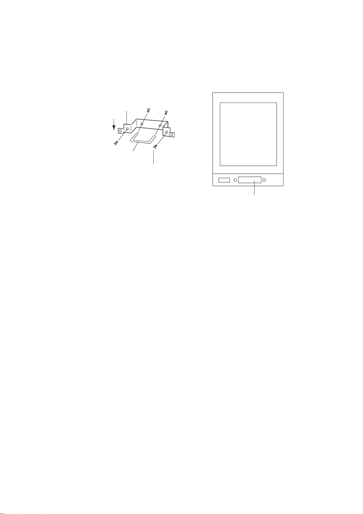
2. Open the monitor and fix it with the stay. (See Chapter 1 for instructions.) Turn
off the internal power switch if so equipped. Unfasten four screws to remove
the shield cover for the INT Board.
3. Fasten the GYRO CONVERTER Board inside the display unit with four washerhead screws (supplied).
PTU BOARD
03P9245A(-F)
MB BOARD
03P9251
GYRO
CONVERTER
BOARD
64P1106
INT BOARD
03P9252
Figure 4-1 Display unit, inside view
4-1
Page 43

4. Connect the GYRO CONVERTER Board to the INT Board (cables supplied
with GC-8) as shown below.
INT Board GYRO CONVERTER Board
J446 (4P) J7 (5P)
J465 (6P) J1 (14P)
J5
To gyro
J4
J446
J465
INT BOARD
03P9252
J7
J1
Fix cable to chassis
with cable tie.
GYRO CONVERTER
BOARD 64P1106
Figure 4-2 Display unit, inside view
5. Confirm gyrocompass specifications and set the DIP switches and jumper wires
on the GYRO CONVERTER Board according to the gyrocompass connected:
• Setting jumper wires and DIP switches by gyrocompass specifications:
page 4-4
• Setting jumper wires and DIP switches by make and model of gyrocompass: page 4-5
• Location of jumper wires and DIP switches: page 4-6
6. Solder the gyrocompass cable to the VH connector assemblies (supplied).
4-2
Page 44

7. Attach instruction label (supplied) to shield cover for the INT and GYRO CONVERTER boards.
8. Close the monitor.
9. Turn the power off and on again to reset the CPU.
Connection of external power supply
An external power supply is necessary when the repeater signal is step-by-step
type and the step voltage is below 20 V or output voltage is less than 5 W.
1. Cut the jumper wire JP1 on the GYRO CONVERTER Board when an external
power supply is used.
2. Connect the gyro cable and power cable as shown below.
GYRO CONVERTER Board
[A] 64P1106
External Power Supply
20 - 135 VAC
20 - 100 VDC
Gyrocompass
(Step type)
S1
S2
S3
COM
F.G.
J5
1 R2
2 R1/COM
Either connection
in case of DC
polarity.
J4
1S1
2 S2
3 S3
4 T
5 F.G.
Figure 4-3 Connection of external power supply to GYRO CONVERTER Board
DIP switch, jumper wire settings
Default setting
The default setting of all DIP switches is off and all jumpers wire are set to “#1.”
(Note that the jumper wire JP1 is set at #1, #2, and #3.) In those settings the
gyrocompass having the following characteristics can be directly connected; modification of the GYRO CONVERTER Board is not necessary.
AC synchronous signal: 50/60 Hz
Rotor voltage: 60 V to 135 V AC
Stator voltage: 60 V to 135 V AC
Gear ratio: 360X
Supply voltage: 30 V to 135 V AC
4-3
Page 45

If the specifications of the gyrocompass differ from those mentioned above, change
jumper wire and DIP switch settings on the GYRO CONVERTER Board as appropriate. Settings may be changed according to gyrocompass specifications (page
4-4) or make and model of gyrocompass (page 4-5). For the location of DIP switches
and jumper wires, see page 4-6.
Setting method 1: DIP switch settings by gyrocompass specifications
epytssapmocoryG)1ycneuqerF)2
ssapmocoryG
epyt
suonorhcnysCAFFOFFOFFO,2#,1#
suonorhcnysCDFFOFFOFFO,3#,2#
petsCDNOFFOFFO,5#,4#
evaw-lluF
evaw-flaH
WS
WS
4-1
FFONOFFO,5#,4#
tnerrucgnitaslup
NONOFFO,5#,4#
tnerrucgnitaslup
egatlovrotoR)3
WS
5-1
6-1
1PJycneuqerFWS
3#
4#
6#
CDNONOsuonorhcnysCD
6#
6#
egatlovrotatS)4
)2R&1Rneewteb(
egatlovrotoR1-2WS3PJegatlovrotatS2-2WS3-2WS2PJ
CAV54otV02NO2#ro,CAV54otV02
CAV07otV03FFO2#
CAV09otV04NO1#ro,CAV54otV02
CAV531otV06FFO1#
CDV06otV02
CDV06otV02
CAV09otV04NOFFO1#
CAV531otV06FFOFFO1#
WS
7-1
zH06/05FFOFFOsuonorhcnysCA
zH004NOFFOsuonorhcnysCA
zH005FFONOsuonorhcnysCA
8-1
skrameR
tnerrucgnitaslup
tnerrucgnitaslup
tnerrucgnitaslup
petsCD
)2Sdna1Sneewteb(
NOFFO2#
FFOFFO2#
oitaR)5egatlovylppuS)6
oitaR1-1WS2-1WS3-1WSegatlovylppuS4PJ5PJ
x063FFOFFOFFOro,CAV54otV02
x081NOFFOFFO
X09FFONOFFOro,CAV531otV03
X63NONOFFO
CDV06otV02
CDV001otV04
2#2#
1#1#
4-4
Page 46

atadtamrof01-DA)7
lavretnixT
3810-AEMN)8
lavretnixT
:etoN sm52.sm002rosm52nielbaliavasilavretnixTehT
seriwrepmujyb6ot1stroproflavretnignittimsnartatadtceleS
.7PJdna6PJ
.tnempiuqerehtollarofsism002;radarrofsi
xT
lavretni
sdnoces2NO
dnoces1FFO
4-2WS
4-5
Page 47

Setting method 2: DIP switch/jumper settings by make and model of gyrocompass
rekaMsledoMnoitacificepSWS
ONURUF007-YGpetsCD
ztuhcsnA3,2dradnatSsuonorhcnysCA
6,4dradnatSsuonorhcnysCA
02dradnatSpetsCD
awagokoY
cetvaN
htialP(
)epyt
htialPIII/IITAGVANsuonorhcnysCA
cemikoT
yrrepS(
)epyt
ikasawaK18-XGsuonorhcnysCA
nworbamrA1-LKM,01-KM
nostreboR08-RKSpetsCD
3/2/A1/1-C
55-B,55-A
007-ZMCpetsCD
005/X003
3/2-SPI
05-ZMC
etoN
11/2/1-SE
002-GT
H/L732RP
12MG
41-KM
T/2/1-DOM
71-SE,041
302/
0006-GTpetsCD
11-MGsuonorhcnysCA
02-KM
4-DOM
/X052-ZMC
/002/001-ZMC
3/1/Z1-D,RJ-C
/201/101-TLG
701/K601/301
011/A11-SE
0002/R222RP
1E-KN,NE-KN
041/031-RSpetsCD
0005/001-GT
/031/753-RP
202/102-TLG
61-SE,021-RS
,1531SEIRES
x081V001
zH06/05
x063
zH06/05
x063
x081V53
zH06/05
x063
x081V42
petsCD
x081V53
zH06/05
x063
pets
x081V53
zH06/05
x063
zH06/05
x63
zH06/05
x09
petsCD
x081V07
x081V07
petsCD
x081V07
x081V42
zH06/05
x09
petsCD
x081V53
zH06/05
x09
petsCD
x081V05
x081V53
rotcellocnepo,eriw-5
V06/05:egatlovrotoR
V22:egatlovrotatS
V06/05:egatlovrotoR
V09:egatlovrotatS
)+(eriw-3,)-(MOC
suonorhcnysCA
V06/05:egatlovrotoR
V22:egatlovrotatS
)-(eriw-3,)+(MOC
x063suonorhcnysCDFFOFFOFFOFFOFFOFFONONO-NOFFO-omeR
)-(eriw-3,)+(MOC
suonorhcnysCA
V001:egatlovrotoR
V09:egatlovrotatS
)-(eriw-3,)+(MOC
V06/05:egatlovrotoR
V86:egatlovrotatS
suonorhcnysCA
V011/001:egatlovrotoR
V09:egatlovrotatS
suonorhcnysCA
V011/001:egatlovrotoR
V22:egatlovrotatS
)-(eriw-3,)+(MOC
rotcellocnepo,eriw-5
)-(eriw-3,)+(MOC
V001:egatlovrotoR
V09:egatlovrotatS
V001:egatlovrotoR
V09:egatlovrotatS
)-(eriw-3,)+(MOC
)+(eriw-3,)-(MOC
WS
WS
WS
WS
WS
WS
WS
WS
WS
1-1
2-1
3-1
4-1
5-1
6-1
7-1
8-1
1-2
NOFFOFFONOFFOFFONONO- FFOFFO,4#
FFOFFOFFOFFOFFOFFOFFOFFOFFONOFFO,1#
FFOFFOFFOFFOFFOFFOFFOFFOFFOFFOFFO,1#
NOFFOFFONOFFOFFONONO-NOFFO,4#
FFOFFOFFOFFOFFOFFOFFOFFOFFONOFFO,1#
NOFFOFFONOFFOFFONONO-NOFFO-omeR
NOFFOFFONOFFOFFONONO-NOFFO,4#
FFOFFOFFOFFOFFOFFOFFOFFOFFOFFOFFO,1#
NOFFOFFONOFFOFFONONO– NOFFO-omeR
FFOFFOFFOFFOFFOFFOFFOFFOFFOFFOFFO,1#
NONOFFOFFOFFOFFOFFOFFOFFOFFOFFO,1#
FFONOFFOFFOFFOFFOFFOFFOFFOFFOFFO,1#
NOFFOFFONOFFOFFONONO– FFOFFO,4#
NOFFOFFONOFFOFFONONO– FFOFFO,4#
NOFFOFFONOFFOFFONONO– FFOFFO,4#
NOFFOFFONOFFOFFONONO– NOFFO,4#
FFONOFFOFFOFFOFFOFFOFFOFFOFFOFFO,1#
NOFFOFFONOFFOFFONONO– NOFFO,4#
FFONOFFOFFOFFOFFOFFOFFOFFOFFOFFO,1#
NOFFOFFONOFFOFFONONO– FFOFFO,4#
NOFFOFFONOFFOFFONONO– NOFFO,4#
WS
2-2
3-2
1PJ2PJ3PJ4PJ5PJ
2#-1#1#
6#,5#
2#2#1#1#
3#,2#
2#1#1#1#
3#,2#
2#– 2#2#
6#,5#
2#2#1#1#
3#,2#
2#–
ev
2#–
ev
2#– 2#2#
6#,5#
1#1#1#1#
3#,2#
2#–
ev
2#2#1#1#
3#,2#
1#1#1#1#
3#,2#
1#1#1#1#
3#,2#
2#– 1#1#
6#,5#
2#– 1#1#
6#,5#
2#– 1#1#
6#,5#
2#– 2#2#
6#,5#
1#1#1#1#
3#,2#
2#– 2#2#
6#,5#
1#1#1#1#
3#,2#
2#– 1#1#
6#,5#
2#– 2#2#
6#,5#
∗∗
∗∗
∗∗
*: Set JP4 and JP5 according to the voltage of the external power supply.
Note: If CMZ-50 has 35VDC, set JP1 to #4, #5, #6.
4-6
Page 48

Location of DIP switches, jumper wires on the GYRO CONVERTER
Board
JP2
(Rotor voltage)
JP3
(Stator voltage)
JP5, JP4
(Supply voltage)
JP1
(Gyro type)
Fuse
(2A)
J5
(Rotor signal input,
external power input)
J4
(Stator signal input)
SW1
DIP switch
(IEC-61162-1 output port)
64P1106
J6
J7
(Data output port #1)
Figure 4-4 GYRO CONVERTER Board
Setting the heading readout on the radar display
J12
(Data output
port #6)
J11
(Data output
port #5)
J10
(Data output
port #4)
SW2
DIP switch
JP6, JP7
(AD formal
data Tx interval)
J9
(Data output port #3)
J8
(Data output port #2)
Confirm that the gyrocompass is giving a reliable readout. Then, set the heading
readout on the radar display as follows:
1. Press the [RADAR MENU] key to display the FUNCTIONS 1 menu.
2. Press the [0] key twice to display the FUNCTIONS 3 menu.
3. Press the [9] key to select the GYRO SETTING option.
4. Rotate the EBL control to align the radar’s HDG readout with the gyrocompass
heading.
5. Press the [ENTER] key to finish.
4-7
Page 49

4.2 ARP Board ARP-26
The ARP Board ARP-26, which provides ARPA functions, is an optional circuit
board which is accommodated in the display unit. Note that the ARP-26 is not
available with the statute mile-type radar.
Necessary Parts: ARP-26-2E (008-485-500)
emaNepyTytQ.oNedoC
draoBPRAB2009P811056-374-800
Installation of the ARP board
1. T urn of f the power . Remove the front panel from the display pedestal by unfastening four screws.
2. Set the ARP Board in the center slot of the PCB card case.
Display pedestal
Top: RP Board (Option)
Middle: ARP Board (Option)
Bottom: SPU Board
Figure 4-5 Display pedestal, inside view
3. Adjust the ARP Board referring to the procedure below.
ARP board adjustment
1. Turn the GAIN, A/C SEA and A/C RAIN controls fully counterclockwise (OFF).
Transmit on the 12 nm range.
2. Connect a digital multimeter between TP7(+) and TP6(-) on the ARP Board.
4-8
Page 50

TP7
TP6
R104
R103
Figure 4-6 ARP Board (18P9002B)
3. Adjust R104 on the ARP Board so the multimeter reads between 0.09 and 0.14
VDC.
4. Set controls and switches as below.
GAIN: fully clockwise (max.)
Interference rejector: OFF
Range: 24 nm
Echo stretch: OFF
5. Press [RADAR MENU] [0] [0] [0] [0] to open the INITIAL SETTING3 menu.
6. Set the VIDEO SIG field to DIGITAL and press the [ENTER] key.
7. Adjust R103 on the ARP Board so noise just appears on the display.
Too little noise
Proper noise
Too much noise
Figure 4-7 How to adjust noise
8. Set VIDEO SIG to ANALOG and press the [ENTER] key.
Final check
Connect a gyrocompass and a log to the radar and place the radar under transmit
state. Confirm that LEDs CR9, CR10, CR11, CR12, CR15 and CR16 on the ARP
Board are off. If ship's speed is zero, or other signal is not being input, corresponding LED will light.
4-9
Page 51

CR16 LOG
CR15 GYRO
CR12 TRG
CR11 VID
CR10 BRG
CR9 HDG
S1
4#3#2#1#
FFOFFOFFOFFO
Figure 4-8 ARP Board (18P9002B)
4.3 RP Board RP-26
The RP Board RP-26, which provides video plotter functions, consists of a circuit
board and a card drive, both of which are accommodated in the display unit. Note
that the RP-26 is not available with the statute mile-type radar.
Table top/console type
Necessary Parts: RP-26-T-2E (Code No. 008-485-520)
emaNepyTytQ.oNedoCskrameR
.yssAesaBdraC-M—1—
draoBPR8920P411046-784-800
BwercSdaeh-naPW0072C8X4M4544-188-000
BwercSdaeh-naPW0072C8X3M2404-188-000desutoN
,.yssaelbaC,draoBFI
,.yssaesabdrac-M
,esacdrac-M,dildrac-M
revocdrac-M
AwercSdaeh-naPW0072C5X6.2M2379-008-000desutoN
AwercSdaeh-naPW0072C8X3M1401-188-000desutoN
rehsawkcoldehteeTW1915C4M1605-468-000
rehsawkcoldehteeTW1915C3M1405-468-000desutoN
1. Open the monitor and fix it with the stay. See page 1-5 for instructions
4-10
Page 52

2. Remove the right arm cover from the control head. Fasten the M-card base
assy. to the right arm cover as follows:
a) Fasten the ground wire with the M4X8 pan-head screw and the M4 teethed
locked washer as shown below.
b) Fasten the right arm cover to the card case with three M4X8 pan-head screws
(supplied).
Pan-head screw
M4X8
Right arm cover
Ground wire
Pan-head screw
M4X8 (3 pcs.)
FRONT
Card slot
Toothed lock
washer M4
M-card base assy.
Figure 4-9 Fastening the M-card base assy. to the right arm cover
3. Unfasten four M4X8 screws from the PCB card case cover from the display
pedestal.
4. Pass the connector from the M-card base assy. through the hole in the display
pedestal.
PCB card slot
PCB card
case cover
Display pedestal
Figure 4-10 Display pedestal
5. Set the RP Board (14P0298) in the top slot of the PCB card case.
4-11
Page 53

6. Run the connector from the M-card base assy. in front of the GYRO CONVERTER Board as in Figure 4-11.
7. Plug the connector from the M-card base assy. in J1 on the RP Board.
8. Fasten the ground wire from the connector at the location shown in Figure 4-
11.
RP connector
INT Board
Fasten ground wire from connector to this screw.
RP Board
ARP Board
SPU Board
Route cable between ARP and SPU Boards.
GYRO
CONVERTER
Board
(TOP VIEW)
J1
(FRONT VIEW)
FRONT
Figure 4-11 Display pedestal, front and top views
9. Fasten the PCB card case cover to the display pedestal.
10.Close the monitor, and then fasten the right arm cover.
Separate type control head
Necessary parts: RP-26-Z-2E (Code no. 008-491-400)
emaNepyTytQ.oNedoCskrameR
.yssAesaBdraC-M—1—
draoBPR8920P411046-784-800
BwercSdaeh-naPW0072C8X4M4544-188-000
BwercSdaeh-naPW0072C8X3M2404-188-000desutoN
AwercSdaeh-naPW0072C5X6.2M2379-008-000desutoN
AwercSdaeh-naPW0072C8X3M1401-188-000desutoN
rehsawkcoldehteeTW1915C4M1605-468-000
rehsawkcoldehteeTW1915C3M1405-468-000desutoN
,.yssaelbaC,draoBFI
.yssaesabdrac-M
4-12
Page 54

1. Open the monitor and fix it with the stay. See page 1-5 for instructions.
2. Fasten the M-card base assy. with one M4X8 pan-head screw as below.
Fasten with
M4 x 8 screws.
Fasten with M3 x 8
screws (2 pcs.)
Figure 4-12 Display unit, inside view
3. Fasten the ground wire with the M3X8 pan-head screw and M3 teethed lock
washer.
4. Fix the M-card case assy. with two M3X8 pan-head screws.
5. Set the M-card case cover to the hole in the front panel and fix with two M2.6X5
pan-head screws.
Pan-head screw B
Pan-head screw A
M3X8
Teethed lock washer
M3
M4X8
M-card base assy.
1
2
3
4
5
6
7
8
8
1
Pan-head screw
M2.6X5, 2 pcs.
Pull forward
and fix.
M-card case cover
Pan-head screw B
M3X8, 2 pcs.
Figure 4-13 Display pedestal, front view
4-13
Page 55

6. Unfasten four M4X8 screws to remove the PCB card case cover at the front of
the display pedestal.
7. Set the RP Board (14P0298) in the top slot of the PCB card case.
8. Run the connector from the card case in front of the GYRO CONVERTER
Board as shown in Figure 4-14.
9. Plug the connector from the M-card base assy . in J1 on the RP Board as shown
in Figure 4-14.
RP connector
INT Board
Fasten ground wire from connector to this screw.
RP Board
ARP Board
SPU Board
Route cable between ARP and SPU Boards.
GYRO
CONVERTER
Board
(TOP VIEW)
J1
(FRONT VIEW)
FRONT
Figure 4-14 Display pedestal, front and top views
10.Fasten the ground wire from the connector at the location shown in Figure 4-
14.
11.Fasten the PCB card case cover to the display pedestal.
12.Close the monitor.
4-14
Page 56

4.4 Performance Monitor PM-30
Necessary parts: PM-30 and OP03-150 (Code no. 008-485-490)
Contents of Performance Monitor Kit OP03-150
emaNepyTytQ.oNedoC
draoBNI-MP5229P301026-784-800
BwercSdaeh-naPW0072C8X3M3404-188-000
.yssArotcennoCAA-003L-P3HV2410-141-000
1. Open the monitor and fix it with the stay. See Chapter 1 for instructions.
2. Fasten the PM Board 03P9225 to the location shown below with three screws
(M3X8).
J403
PM Board
03P9225
J401
J411
J402
Figure 4-15 Display unit, inside view
3. Connect J411 to J401 on the PM Board.
4. Connect two connector assemblies (VH3P-L300-AA) to J402 and J403.
5. Solder the other end of the connector assemblies with external cables, one
from ship’s mains and one from the PM-30.
6. Close the monitor.
4-15
Page 57

4.5 Alarm Kit
Necessary parts: OP03-156 (Code no. 008-500-650)
The alarm kit mainly consists of a circuit board and connection cables, and provides alarm output to ship’s bridge alarm system.
Contents of Alarm Kit OP03-156
emaNepyT.oNedoCytQ
draoBMRALA2629P30086-005-8001
.yssArotcennoCHN)P9-9(0991-30007-005-8001
.yssArotcennoCHN)P3(1991-30017-005-8004
dnaBelbaCN3-PH100-075-0001
eiTelbaC001-VC223-075-0003
BwercSdaeh-naPW0072C8X3M404-188-0004
BwercSdaeh-naPW0072C21X4M744-188-0001
Procedure
Refer to the figure below for parts locations.
1. Raise the monitor and fix it with the stay. (See page 1-5 for instructions.)
2. Unfasten four screws to dismount the shield cover for the INT Board.
3. Fasten the ALARM Board to the display unit with four pan-head screws (M3X8,
supplied).
4. Connect the NH connector (9-9P, supplied) between J471 on the ALARM Board
and J451 (EXT-BUZ) on the INT Board, passing it through the cable band and
binding it with existing cable tie.
5. Fasten the cable band (supplied) with a pan-head screw (M4X12, supplied)
and attach two cable ties (CV-100, supplied).
6. Connect an NH connector (3P, supplied) to each of J472, J473, J474 and J475
on the ALARM Board.
7. Route the NH connectors along the cables ties and pass them through the
cable clamp. Fasten the shield cover removed at step 1.
8. Close the INT board cover.
9. Close the monitor.
10.Connect NH connectors to ship’s bridge alarm system:
J472: ARPA guard zone; target alarm
J473: SYSTEM FAILURE (HP, BP, TRIG, VIDEO, GYRO, AZI)
J474: ARP A CP A/TCP A
J475: Spare
4-16
Page 58

A
A
Pass cable
through here.
Cable Tie CV -100,
2 pcs.
J451
INT Board
03P9252
Existing cable tie
Figure 4-16 Display unit, inside view
HOW TO INSULATE THE POWER CABLE
Shrink Tubing
Solder
20 mm
J475
J474
J473
J471
J472
Pan-head Screw
M3X8, 4 pcs.
NH Connector
03-1991(3P), 4 pcs.
ALARM Board
03P9262
NH Connector
03-1990(9-9P)
Pan-head screw
M4X12
Cable Band
HP-3N
1 Make length of
shrink tubing 20 mm;
slip tubing onto wiring.
2 Solder power
cable to signal cable.
4-17
Heat shrink
3
tubing with soldering iron.
Page 59

4.6 AC-DC Conversion Kit
The AC-DC Conversion Kit enables conversion from AC power to DC power, and
mainly consists of a circuit board and filter.
)annetnampr42rof(tiKnoisrevnoCCD-CA
067-994-800:.oNedoC,42-161-30PO:epyT
emaNepyT.oNedoCytQemaNepyT.oNedoCytQ
REWOP
draoB
retliF)CD(421-PDR064-294-8001retliF)CD(421-PDR064-294-8001
A6429P30044-784-8001REWOP
draoB
C6429P30007-394-8001
)annetnampr24rof(tiKnoisrevnoCCD-CA
77-994-800:.oNedoC,24-161-30PO:epyT
1. Slide the monitor forward until the PTU Board and filter are in view and easily
accessed.
2. Follow (2) and (3) on page 1-8 to remove the PTU Board cover.
3. Unplug all connectors from the PTU Board.
4. Loosen the screws fixing the PTU Board, and then remove the PTU Board.
5. Fasten new PTU Board with screws removed in step 4.
6. Plug in six connectors to their proper locations on the PTU Board. Do not connect J101.
7. Loosen four screws fixing the AC filter.
8. Fasten new filter.
9. Connect cable from filter to J101 on the PTU Board.
10.Fasten the PTU board cover.
11.Connect power cable from ship’s mains.
12. Close the monitor.
PTU Board (behind shield cover)
J106
(M3X8, 5 pcs.)
Screw
Slide forward
h
Knob
J105
*
J104
J103
*
J446
Screw (M4X8, 2 pcs.)
J466
J462
J465
*
*
*
Power cable
leads
Unfasten
screws.
Filter
(Shown:
AC type)
Figure 4-17 Display unit, inside view
4-18
Page 60

4.7 Connection of Rate-of-Turn Signal
Connection
1. Connect cable DPYC-1.25 or equivalent to the ROT device.
2. Raise the monitor and fix it with the stay. See page 1-5 for procedure.
3. Remove the INT board shield cover by loosening four screws.
4. Connect the DPYC-1.25 to J453 on the INT Board.
Checking operation
1. Turn on both the ROT device and the radar . Confirm that both the radar and the
ROT device are showing the same ROT indication.
2. If the indications are the same close the INT board shield cover and monitor. If
the indications are different do the following:
a) Adjust R151 on the INT Board so that R150 reads 0 ±0.1 V. Adjust R153 to
show the same indication as the ROT device.
b) Close the INT board shield cover. Retract the stay to lower the monitor.
PTU Board
Cover
MOTHER BOARD
03P9251
INT BOARD
03P9252
J453
J463
R153
R151
R150
Figure 4-18 Display unit, inside view
4-19
Page 61

4.8 V-Console Kit
Display unit
Hex Bolt
M10X30, 4 pcs.
Spring Washer
M10, 4 pcs.
Console
The V-console kit mounts the display unit atop a console.
Necessary parts: OP03-164 (Code no. 000-089-762)
1. Fasten the console to the deck as shown on page 1-8.
Contents of V-Console Kit OP03-164
emaNepyT.oNedoCytQ
elosnoC--1
tloBeyE01-CB-03-PC804-808-0004
drauGegdE0-6181-441-30039-172-0011
tloBxeH03x01M281-208-0004
wercSgnidniB0072C8x4M704-608-0006
rehsaWgnirpS01M162-468-0004
revoCraeR0-1971-441-30085-472-0011
2. Set the display on the top of the console and fasten it with four hex bolts (M10X30)
and four spring washers (M10).
Figure 4-19 Fastening the display unit to the console
4-20
Page 62

3. Unfasten the cable clamp at the rear of the display unit.
REAR VIEW
Rear Cover
03-144-1791-0
Binding Screw
M4X8, 6 pcs.
4. Using the bolts used to fix the cable clamp fasten the edge guard to the cable
entrance as shown below. (The edge guard protects cables from damage.)
Edge Guard
03-144-1816-0
J106
J105
*
J104
J103
*
J446
J466
J462
J465
*
*
*
Figure 4-20 How to fasten the edge guard
5. Wire the display unit, referring to page 2-9.
6. Fasten the rear cover (supplied) at the rear of the display unit with six binding
screws (M4X8).
Figure 4-21 How to fasten rear cover
4-21
Page 63

Page 64

Page 65

Page 66

Page 67

Page 68

Page 69

Page 70
Page 71

Page 72

Page 73

Page 74

Page 75

Page 76
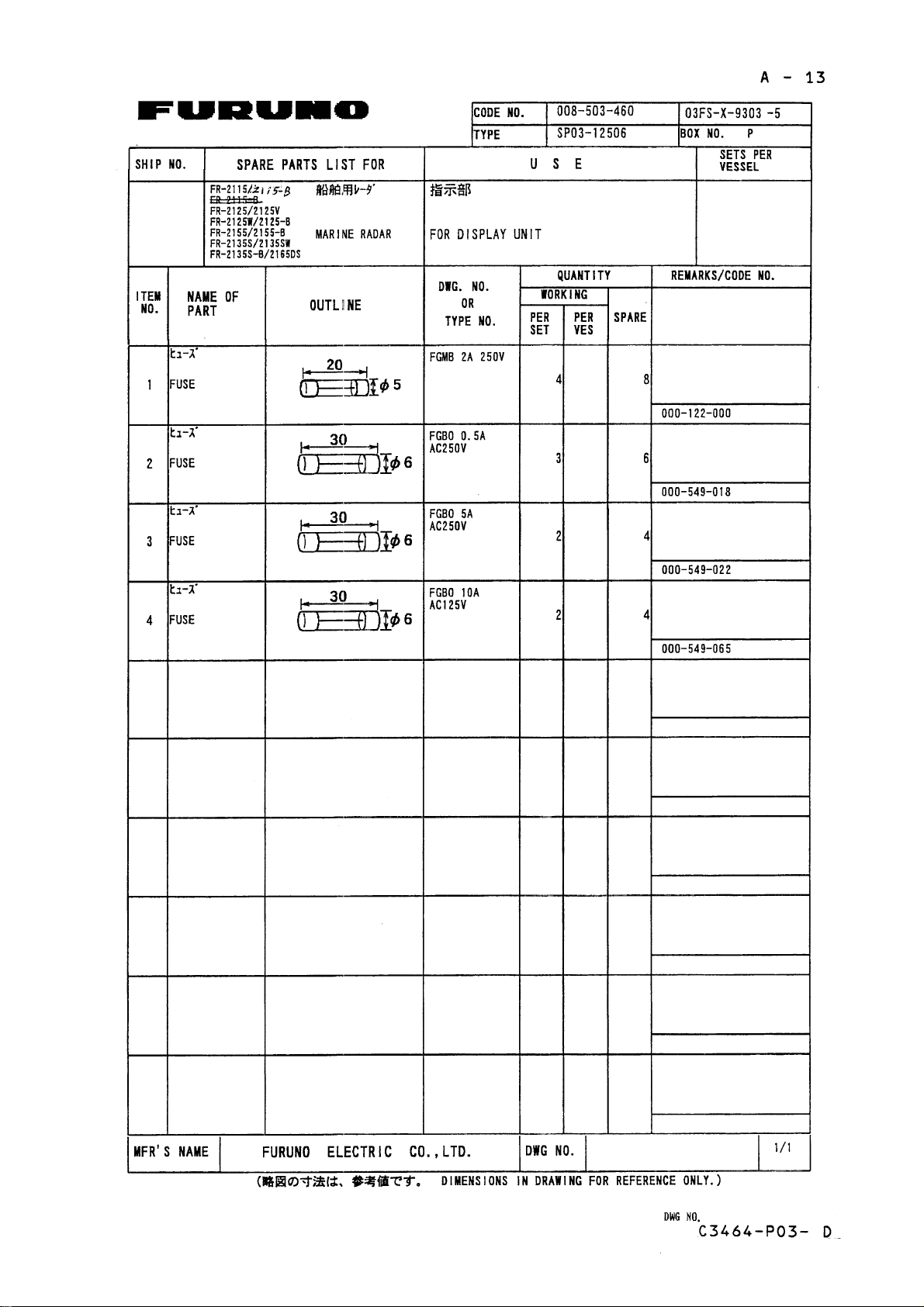
Page 77

Page 78

Page 79

Page 80

Page 81

Page 82

Page 83

Page 84

Page 85

Page 86

Page 87

Page 88

Page 89

Page 90

 Loading...