

Page 1

New standard of marine radar technology through
50 years of FURUNO’s marine electronics activit ies
21” MULTI-COLOR HIGH-PERFORMANCE
SHIPBORNE RADAR AND ARPA
MODEL
FR-2105/2105-B SERIES
FURUNO ELECTRI C CO. , LTD.
NISHINOMIYA, JAPAN
Page 2

A
(
C
9-52, Ashihara-cho,
Nishinomiya, Japan
Telephone: 0798-65-2111
Telefax: 0798-65-4200
ll rights reserved.
Printed in Japan
Your Local Agent/Dealer
FIRST EDITION : JUL. 1998
U : JUN. 6, 2001
PUB. No. OME-34640
TATA)
FR-2105/2105-B SERIES
Page 3
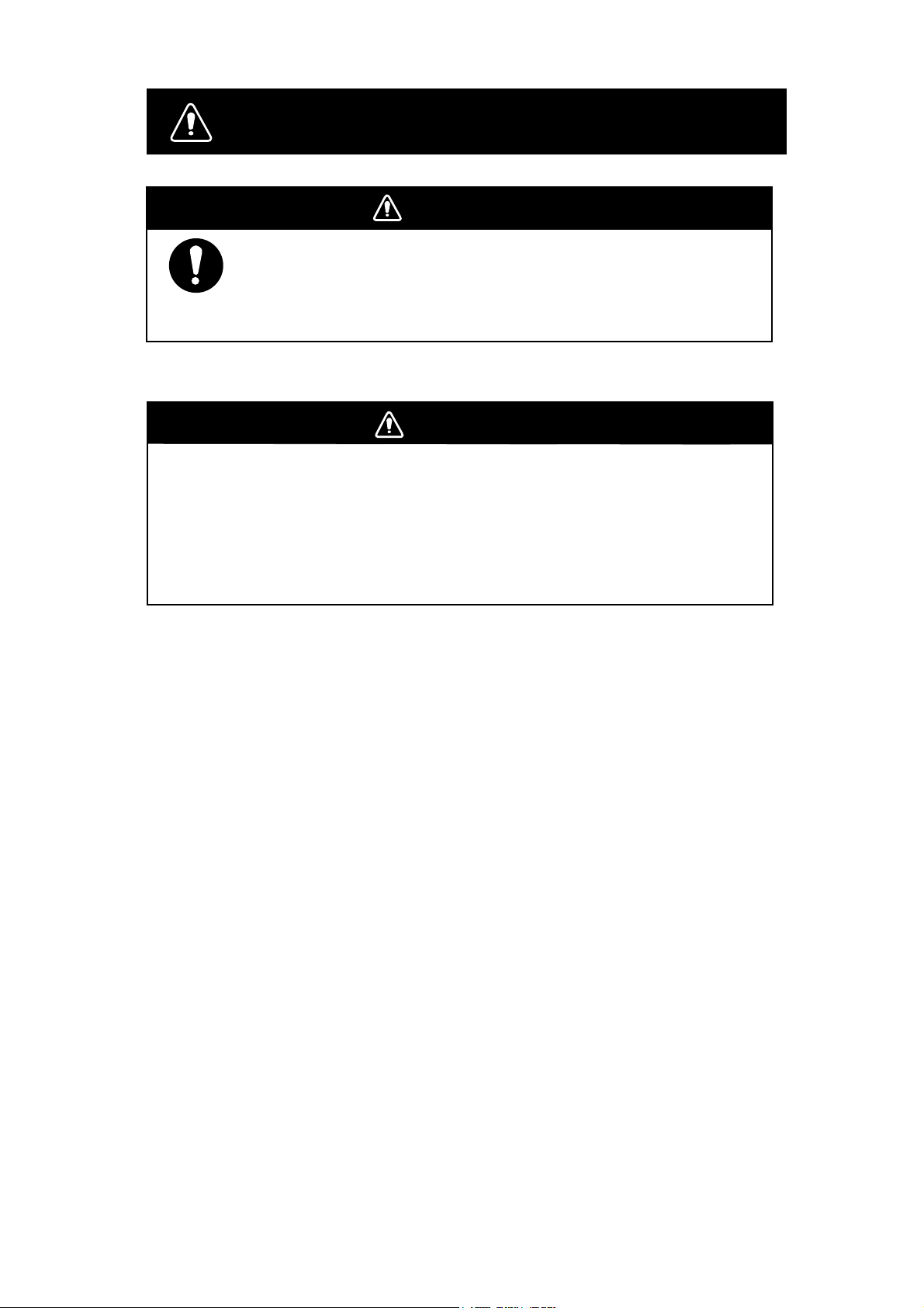
SAFETY INSTRUCTIONS
DANGER
Before turning on the radar, make sure that there is no one near the
scanner unit.
Serious injury or even death may result if a rotating antenna strikes
someone standing nearby.
WARNING
Radio Frequency Radiation Hazard
The radar antenna emits electromagnetic radio frequency (RF) energy which can be
harmful, particularly to your eyes. Never look directly into the antenna aperture from a
close distance while the radar is in operation or expose yourself to the transmitting
antenna at a close distance.
i
Page 4
WARNING
WARNING
ELECTRICAL SHOCK HAZARD
Do not open the equipment.
Only qualified personnel
should work inside the
equipment.
Turn off the radar power
switch before servicing the
scanner unit. Post a warning sign near the switch
indicating it should not be
turned on while the scanner
unit is being serviced.
Prevent the potential risk of
being struck by the rotating
scanner and exposure to
RF radiation hazard.
Wear a safety belt and hard
hat when working on the
scanner unit.
Serious injury or death can
result if someone falls from
the radar scanner mast.
Do not disassemble or modify the
equipment.
Do not place liquid-filled containers on
the top of the equipment.
Fire or electrical shock can result if a liquid
spills into the equipment.
Do not operate the equipment with wet
hands.
Electrical shock can result.
Keep heater away from equipment.
Heat can alter equipment shape and melt
the power cord, which can cause fire or
electrical shock.
CAUTION
Do not use the equipment for other than
its intended purpose.
Use of the equipment as a stepping stool,
for example, can result in personal injury
or equipment damage.
Fire, electrical shock or serious injury can
result.
Turn off the power immediately if water
leaks into the equipment or the equipment is emitting smoke or fire.
Continued use of the equipment can cause
fire or electrical shock.
No one navigation device should ever be
solely replied upon for the navigation of
a vessel.
Always confirm position against all available
aids to navigation, for safety of vessel and
crew.
ii
Page 5

ARPA Safety Instructions
WARNING
No one navigational aid should be relied
upon for the safety of vessel and crew.
The navigator has the responsibility to
check all aids available to confirm
position. Electronic aids are not
a substitute for basic navigational
principles and common sense.
• This auto plotter automatically tracks an
automatically or manually acquired radar
target and calculates its course and
speed, indicating them by a vector. Since
the data generated by the auto plotter
are based on what radar targets are
selected, the radar must always be
optimally tuned for use with the auto
plotter, to ensure required targets will not
be lost or unwanted targets such as sea
returns and noise will not be acquired
and tracked.
• A target does not always mean a land mass, reef, ships or other surface vessels
but can imply returns from sea surface
and clutter. As the level of clutter changes
with environment, the operator should
properly adjust the A/C SEA, A/C RAIN
and GAIN controls to be sure target
echoes are not eliminated from the
radar screen.
CAUTION
The plotting accuracy and response of
this auto plotter meets IMO standards.
Tracking accuracy is affected by the
following:
• Tracking accuracy is affected by course
change. One to two minutes is required to
restore vectors to full accuracy after an
abrupt course change. (The actual
amount depends on gyrocompass
specifications.)
• The amount of tracking delay is inversely
proportional to the relative speed of the
target. Delay is on the order of 15—30
seconds for high relative speed; 30—60
seconds for low relative speed.
Display accuracy is affected by the
following:
• Echo intensity
• Radar transmission pulsewidth
• Radar bearing error
• Gyrocompass error
• Course change (own ship or target)
iii
Page 6
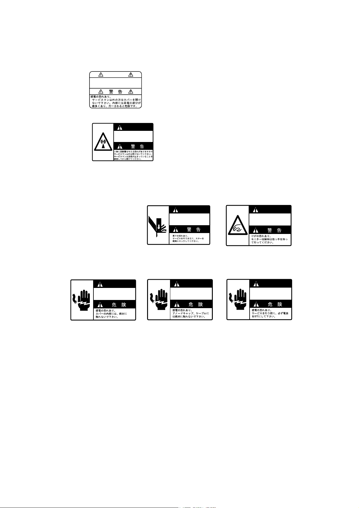
Several labels are attached to the display
unit and scanner unit.Do not remove these labels.
If a label is peeling off or is illegible, contact a
FURUNO agent or dealer.
<Display Unit>
Name: Warning Label (1)
Type: 86-003-1011-0
Code no.: 100-236-230
<Scanner Unit>
Name: Radiation Warning
Label
Type: 03-142-3201-0
Code no.: 100-266-890
WARNING
To avoid electrical shock, do not
remove cover. No user-serviceable
parts inside.
WARNING
Radiation hazard. Only qualified
personnel should work inside scanner.
Confirm that TX has stopped before
opening scanner.
<Inside of the Display Unit>
WARNING
Display unit may fall.
Lock stay before
servicing.
ARNING
WARNING
Possibility of injuly.
Hold handle when
mounting display unit.
ANGER
DANGER
Electrical shock hazard.
Do not touch parts inside
this cover.
Name : Danger Label
Type : 14-055-4202
Code No. : 100-245-220
Name : Warning Label
Type : 03-144-1332
Code No. : 100-266-290
ANGER
DANGER
Electrical shock hazard.
Do not touch anode cap
or its cable.
Name : Danger Label
Type : 14-055-4201
Code No. : 100-243-450
Name : Warning Label
Type : 03-144-1333
Code No. : 100-266-300
ANGER
DANGER
Electrical shock hazard.
Turn off power before
servicing.
Name : Danger Label
Type : 66-022-2012
Code No. : 100-237-730
iv
Page 7

TABLE OF CONTENTS
INTRODUCTION ...........................................................................................................................................viii
A W
ORD TO THE OWNER OF
S
PECIFICATIONS OF
FURUNO R
FR-2105/2105-B S
.................................................................................................
ADAR
ERIES RADAR AND
ARPA.......................................................................XI
VIII
CHAPTER 1 OPERATION............................................................................................................................1.1
URNING ON THE POWER
1.1 T
1.2 T
RANSMITTER
1.3 C
ONTROL HEAD
1.4 CRT B
1.5 T
1.6 O
1.7 D
1.8 I
1.9 P
1.10 S
1.11 S
1.12 A
1.13 S
1.14 S
RILLIANCE
UNING THE RECEIVER
N-SCREEN LEGENDS AND MARKERS
EGAUSSING THE
NITIALIZING THE GYRO READOUT
RESENTATION MODES
ELECTING THE RANGE SCALE
ELECTING THE PULSELENGTH
DJUSTING THE SENSITIVITY
UPPRESSING SEA CLUTTER
UPPRESSING PRECIPITATION CLUTTER
ON.........................................................................................................................................2
............................................................................................................................................3
..........................................................................................................................................5
CRT S
..............................................................................................................................1
.................................................................................................................................5
............................................................................................................7
....................................................................................................................9
CREEN
..................................................................................................................9
...............................................................................................................................10
..................................................................................................................13
..................................................................................................................13
.....................................................................................................................16
.....................................................................................................................16
....................................................................................................18
1.15 I
NTERFERENCE REJECTOR
1.16 M
1.17 M
1.18 C
1.19 M
1.20 S
1.21 O
1.22 E
1.23 E
1.24 E
1.25 E
1.26 T
1.27 P
1.28 O
1.29 Z
1.30 M
1.31 M
EASURING THE RANGE
EASURING THE BEARING
OLLISION ASSESSMENT BY OFFSET
EASURING RANGE AND BEARING BETWEEN TWO TARGETS
ETTING A TARGET ALARM ZONE
FF-CENTERING
CHO STRETCH
CHO AVERAGING
LECTRONIC PLOTTING AID
NTERING OWN SHIP'S SPEED
ARGET TRAILS (ECHO TRAILS
ARALLEL INDEX LINES
RIGIN MARK
.......................................................................................................................................................41
OOM
ARKERS
ENU KEYS
.......................................................................................................................................25
........................................................................................................................................26
.....................................................................................................................................27
...........................................................................................................................................40
.................................................................................................................................................42
..............................................................................................................................................43
........................................................................................................................18
...........................................................................................................................19
.........................................................................................................................21
EBL .................................................................................................22
......................................................................23
..............................................................................................................23
(EPA) ............................................................................................................29
....................................................................................................................33
).................................................................................................................35
.............................................................................................................................38
1.32 RADAR 1, 2
1.33 F
UNCTION KEYS
AND
3 M
ENU SETTINGS
........................................................................................................44
.......................................................................................................................................46
v
Page 8

1.34 B
ARGE INFORMATION
................................................................................................................................52
1.35 R
ADAR MAP
1.36 S
UPPRESSING SECOND-TRACE ECHOES
1.37 D
ISPLAYING EXTERNAL WAYPOINT AND NAVIGATION LINE
1.38 A
DJUSTING BRILLIANCE OF SCREEN DATA
1.39 D
ISPLAY OF WIND/TIDE/DEPTH INFORMATION
1.40 A
LARMS
..............................................................................................................................................52
....................................................................................................57
..........................................................................57
.................................................................................................58
............................................................................................59
....................................................................................................................................................61
CHAPTER 2 OPERATION OF ARPA (OPTION) .........................................................................................2.1
ENERAL
2.1 G
2.2 K
EYPADS FOR
2.3 ARPA M
2.4 S
TART-UP PROCEDURE
2.5 A
UTOMATIC ACQUISITION
2.6 M
ANUAL ACQUISITION
2.7 C
HANGING PLOT SYMBOL SIZE
2.8 A
DJUSTING BRILLIANCE OF PLOT MARKS
2.9 D
ISPLAYING TARGET DATA
2.10 V
ECTOR MODES
.....................................................................................................................................................1
ARPA....................................................................................................................................2
ENU OPERATION
.............................................................................................................................3
.................................................................................................................................4
..............................................................................................................................6
.................................................................................................................................10
....................................................................................................................11
.....................................................................................................14
..........................................................................................................................14
........................................................................................................................................15
2.11 P
AST POSITION DISPLAY
2.12 S
ET AND DRIFT (SET AND RATE
2.13 S
ETTING
2.14 S
ETTING A GUARD ZONE
2.15 O
PERATIONAL WARNINGS
2.16 T
RIAL MANEUVER
2.17 ARPA P
2.18 C
RITERIA FOR SELECTING TARGETS FOR TRACKING
2.19 F
ACTORS AFFECTING
CPA/TCPA A
ERFORMANCE TEST
...........................................................................................................................16
) ...............................................................................................................17
LARM RANGES
.......................................................................................................18
...........................................................................................................................19
.........................................................................................................................21
.....................................................................................................................................23
.....................................................................................................................25
...................................................................................26
ARPA F
UNCTIONS
...................................................................................................28
CHAPTER 3 RADAR OBSERVATION.........................................................................................................3.1
ENERAL
3.1 G
3.2 F
ALSE ECHOES
3.3 SART (S
3.4
RACON (R
.....................................................................................................................................................1
.............................................................................................................................................3
EARCH AND RESCUE TRANSPONDER
ADAR BEACON
)............................................................................................................................7
) ..............................................................................................3
CHAPTER 4 OPERATION OF VIDEO PLOTTER .....................................................................................4.1
4.1 G
ENERAL
4.2 T
HE VIDEO PLOTTER DISPLAY
.....................................................................................................................................................1
.......................................................................................................................2
4.3 D
ISPLAY MODES
4.4 S
ET- UP OF VIDEO PLOTTER DISPLAY
4.5 T
..........................................................................................................................................................5
RACK
...........................................................................................................................................2
............................................................................................................4
vi
Page 9

4.6 MARKS, LINES ..............................................................................................................................................8
4.7 W
AYPOINTS..................................................................................................................................................9
4.8 N
AVIGATION LINES......................................................................................................................................12
4.9 R
ECORDING & REPLAYING DATA .................................................................................................................14
4.10 P
LOTTER PRESENTATION MODE ................................................................................................................16
4.11 I
NITIAL SETTINGS ......................................................................................................................................17
LATITUDE ERROR TABLE (ON 96 NM RANGE SCALR).........................................................17
4.12
CHAPTER 5 MAINTENANCE..................................................................................................................5.1
5.1 P
ERIODIC MAINTENANCE SCHEDULE..............................................................................................................1
5.2 L
IFE EXPECTANCY OF MAJOR PARTS .............................................................................................................2
5.3 R
EPLACEMENT OF BATTERY ..........................................................................................................................2
CHAPTER 6 TROUBLESHOOTING........................................................................................................6.1
6.1 E
ASY TROUBLESHOOTING .............................................................................................................................1
6.2 A
DVANCED-LEVEL TROUBLESHOOTING...........................................................................................................2
6.3 D
IAGNOSTIC TEST .........................................................................................................................................4
CHAPTER 7 MENU OVERVIEW..............................................................................................................7.1
CHAPTER 8 ANLILLARY EQUIPMENT..................................................................................................8.1
8.1
PERFORMANCE MONITOR..............................................................................................................................1
8.2
INTERSWITCHING UNIT...................................................................................................................................3
8.3 F
OR FISHING VESSEL....................................................................................................................................4
CHAPTER 9 DIGITAL INTERFACE (IEC61162-1)..................................................................................9.1
CHAPTER 10 PARTS LIST AND MAJOR PARTS LOCATION .............................................................10.1
Declaration of Conformity to Type (FR-21X5 series)
Declaration of Conformity (FR-2155, FR-2165DS)
vii
Page 10

INTRODUCTION
A Word to the Owner of FURUNO Radar
Thank you for purchasing this FURUNO radar. We are confident you will discover why
FURUNO has become synonymous with quality and reliability.
Dedicated in the design and manufacture of marine electronics equipment for half a century,
FURUNO Electric Company has gained an unrivaled reputation as a world leader in the
industry. This is the result of our technical excellence as well as our worldwide distribution and
service network.
Please carefully read and follow the safety information and operating and maintenance
instructions set forth in this manual before attempting to operate the equipment and conduct
any maintenance. Your radar set will perform to the utmost of its ability only if it is operated
and maintained in accordance with the correct procedures.
FEATURES OF THIS SERIES OF RADARS AND ARPAs
■
Daylight-bright rasterscan 21-inch multi-color, high-resolution display
■
New microprocessing technology with high-speed high-density gate array and softwar e
expertise
■
New cast aluminum scanner gearbox and new series of radiators
■
Easy operation by combination of discrete keys, rotary contr ols, and menu operation, all
logically arranged and configured
■
Electronic Plotting Aid (EPA) fitted standard, Automatic Radar Plotting Aid (ARPA) option
exceeding IMO and IEC standards .
■
Reliable CPA and T CPA war n ing in any plott ing m ode, accur ate tar get dat a.
■
Stand-alone or integr ated conf iguration
■
Meets IMO MSC.64 (61) and IE C A.823 : 1996 as a shipborne radar , high speed craf t r adar
A.820 (19), and ARPA A.823 (19).
viii
Page 11

FR-2105/2105-B Series of Radars and ARPAs
The FURUNO FR-2105/2105-B Series of radars and ARPAs are designed to meet various
customers’ needs and the exacting requirements of international and national standards and
regulations including:
- IMO A.477(XII): Performance Standards for Radar Equipment (up to 31.12.1998)
- IMO MSC.64(67) Annex 4: Performance Standar ds for Radar E quipment (1.1.1999 and after)
- IEC 60936-1: Shipborne Radar Operational and Performance Requirement (1.1. 1999 and
after)
- IMO A.823(19): Performance standards for Automatic Radar Plotting Aids (ARPAs) (1.1.1997
and after)
- IEC 60872-1: Automatic Radar Plotting Aids (ARPAs) (1.1.1997 and after)
- IEC 60945: 1996-11(3rd Ed) Marine Navigational E quipment Gener al Requirements
- IMO A.820(19): Performance standards for navigational radar equipment for high speed craf t
(1.1.1996 and after)
- IEC 60936-2: Performance standards for navigational radar equipment f or high speed craf t
Models
This series of radar and ARPA is available in the following models:
Model
Freq Band Output Transceiver configuration
FR-2115,FR-2115-B X-band 12 kW TR-up
FR-2125, FR-2125-B X-band 25 kW TR-up
FR-2125W, FR-2125W-B X-band 25 kW TR-down
FR-2155, FR-2155-B X-band 50 kW TR-up
FR-2135S, FR-2135S-B S-band 30 kW TR-up
FR-2135SW, FR-2135SW-B S-band 30 kW TR-down
FR-2165DS S-band 60 kW TR-up
Note: FR-2155, FR-2155-B, FR-2165DS are not IMO type-approved models.
All comes with the EPA (Electronic Plotting Aid) standard fitted. An optional ARP-26 board is
available to provide the full functionality of ARPA (Automatic Radar Plotting Aid). Also with
an optional Video Plotter RP-26 board.
Besides the choice of the above models, the FR-2105/2105-B Series is available in the Regular
type (R-type) and IMO type. The IMO type is designed as a primary radar under the 1974
SOLAS Convention on ships below 10,000 GT and also as a high speed craft radar when fitted
with ARPA function (at least ATA by IEC 60936-2). The R-type satisfies the IMO and IEC
standards but includes more flexibility of functionality to meet the fishing boats particularly
(thus, this is an expanded type in other word).
ix
Page 12

The table below shows the differences between R-type and IMO type radars. Other functions
and specifications are common. The operator cannot navigate between these two types. Your
radar is factory set for IMO type. If you want an R-type, please ask your service representative.
Function IMO type Regular type (R-type), Japanese
version
Range scales 0.125, 0.25, 0.5, 0. 75, 1. 5, 3, 6, 12,
24, 48, 96 nm
Alarm zones Radar: Target Alarm Z one:
1st TAZ between 3 and 6 nm, 2nd
TAZ anywhere provided the 1st TAZ
is valid.
ARPA: Guard Zones:
1st GZ - between 3 and 6 nm, in 0.5
nm range depth
2nd GZ - Anywhere in 0.5 nm range
depth, but needs 1st GZ operative
x2 Zoom Not available Available on menu
Echo colors Monochrome yellow or green in 16
tones
FR-2115/2115-B:
0.125, 0.25, 0.5, 0. 75, 1. 5, 3, 6, 12,
24, 48, 72 nm
Other models:
0.125, 0.25, 0.5, 0. 75, 1. 5, 3, 6, 12,
24, 48, 120 nm
Radar: Target Alarm Zone:
1st and 2nd TAZs anywhere. Alarm
can be selected for inside (as TAZ) or
outside (as off-zone watch) mode.
ARPA: Guard Zones:
1st GZ - Anywhere in 0.5 nm depth
2nd GZ - Anywhere in 0.5 nm depth
Choice of monochrome in 16 tones or
3 colors depending on echo strengths
Progra m num be r
MAIN 0359149103
ARPA 1859038103
DISP 1859039101
RP 0359150102
(See page 6.6 to confirm this on the screen.)
x
Page 13
Specifications of FR-2105/2105-B Series Radar and ARPA
ANTENNA RADIATOR
1. Type Slotted waveguide array
2. Beamwidth and sidelobe attenuation
Radiator
Type
Length (mm) 1260 2040 2550 3090 3765
Beamwidth
(H)
Beamwidth
(V)
Sidelobe att.
Within ±10°
Sidelobe att.
Outside ±10°
XN12AF XN20AF XN24AF SN30AF SN36AF
1.8° 1.23° 0.95° 2.5° 2.1°
28 dB 28 dB 28 dB 24dB 24 dB
32dB 32 dB 32dB 30 dB 30 dB
X-band S-band
20° 20° 20° 25° 25°
* SN30AF is available for non-SOLAS ship or for HSC
radar (FR-2135S)
3. Rotation
. FR-2115/2125/2115-B/2125-B: 24/42 rpm
. FR-2125W/2135SW/2125W-B/2135SW-B:
26 rpm (60 Hz), 21 rpm (50 Hz)
. FR-2135S/2135S-B:
26 rpm (60 Hz), 21 rpm (50Hz), 45 rpm (for HSC)
. FR-2155/2155-B: 20 rpm (DC and 60 Hz),
16 rpm (50 Hz)
. FR-2165DS: 24 rpm
RF TRANSCEIVER
1. Frequency
X-band 9410 MHz ± 30 MHz (12, 25 kW)
9415 MHz ± 30 MHz (50 kW)
S-band 3050 MHz ± 30 MHz (35, 60 kW)
2. Output power
FR-2115/2115-B : 12 kW,
FR-2125/2125W/2125-B/2125W-B: 25 kW,
FR-2155/2155-B: 50 kW
FR-2165DS: 60 kW,
FR-2135S/2135SW/2135S-B/2135SW-B: 30 kW
3. Pulselengths and PRR
<FR-2115/2125/2115-B/2125-B>
Range scales P/L (µs) PRR (Hz)
0.125, 0.25 0.07 3000
0.5 0.07.0.15 3000
0.75, 1.5 2 from 0.07/0.15/0.3 3000/1500
3 2 from 0.15/0.3/0.5/0.7 3000/1500
6 2 from 0.3/0.5/0.7/1.2 1500/1000
12, 24 2 from 0.5/0.7/1.2 1000/600
48, 96 1.2 600/500
<FR-2155/2125W/2135S/2135SW/2165DS/
2155-B/2125W-B/2135S-B/2135SW-B>
Range scales P/L (µs) PRR (Hz)
0.125, 0.25, 0.5 0.08 2200
0.75, 1.5 0.08/0.3* 2200/1100
3 2 from 0.08/0.3*/0.6 2200/1100
6 2 from 0.08/0.3*/0.6 2200/1100
12, 24 0.6/1.2 1100/600
48, 96 1.2 600/500
*: In case of FR-2155/2165DS/2155-B, 0.3 is replaced
with 0.2.
4. IF 60 MHz, Logarithmic. BW 28/3 MHz
5. Noise figure 6 dB
6. Duplexer Ferrite circulator with diode limiter for
FR-2115/2125/2135S/2135SW/
2115-B/2125-B/2135S-B/
2135SW-B/2165DS.
Ferrite circulator with TR limiter for
FR-2155/2155-B/2125W/2125W-B.
DISPLAY
1. Picture tube 21” multi-color, 1280 x 1024 pixels,
Rasterscan non-interlace at 61.44
kHz hor, 60 Hz vert.
Effective display diameter 275 mm
IMO type Yellow or green echoes in 16 levels.
Echoes in the same color in 16
graduation for smooth display.
Different colors for marks, legends,
alarms to ensure easy observation.
Regular type Yellow or green echoes in 16 levels
or 3 colors depending on echo
strengths
2. Minimum range and discrimination
Meets 35 m HSC requirements
3. Range scales 0.125, 0.25, 0.5, 0.75, 1.5, 3, 6, 12,24,
48, 96
Max. range for Japanese version is
Note:
FR-2115/2115-B: 72 nm, Other: 120 nm
4. Range accuracy 1% of range or 15 m, whichever is
the greater
5. Bearing discrimination Better than 2.5° except 9 ft
S-band radiator. Accuracy ±1°
6. Presentation Head-up, Head-up TB, North-up, TM
Sea or ground stabilization
7. Plotting facilities
EPA 10 targets manual plotting (standard).
Not operational in ARPA mode.
ARPA Automatic Radar Plotting Aid for 30
targets automatically or manually
acquired, dynamic and static trial
maneuver, complies with A.823(19).
Common features Sea and ground stabilized vectors
and target trails, 3 target data readout
at a time
8. Radar map Nav lines, coastlines, buoys, etc.
produced by operator as required by
IMO and IEC standards. 150 points x
10 areas stored in EEROM.
9. Guard zone 2 GZs at 3 and 6 nm in width of 0.5
nm, any sector, in ARPA mode.
10. Target alarm zone 1st zone within 3-6 nm, 2nd zone
anywhere
11. Target trails Plotted in light blue not to interfere
with radar picture, intervals 15, 30 s,
1, 3, 6, 15, 30 min, true or relative on
RM mode; true only in TM mode.
xi
Page 14

12. Parallel index line Choice of 2, 3 or 6 lines
INTERFACE
IEC 61162-1 OSD, RSD, TTM, etc.
(LISTENER 2 mA at 2 V, TALKER
60 mA max.)
Analog RGB video, H/V sync for VDR with
optional interface board
Gyrocompass Built-in interface for sync signal
20-50 V, 50-400 Hz, or stepper
20-50 V
Speed log IEC 61162-1, contact closure or
200/400/500 pulses/nm
EQUIPMENT LIST
Standard
1 Display unit (Separated to Monitor, Processor unit and
Control unit for –B type model)
2 Antenna unit
3 Transceiver unit for TR down version;
FR-2125W/2135SW/2125W -B/2135SW-B
4 Power supply unit for
FR-2155/2135S/2135SW/2165DS/2155-B/
2135S-B/2135SW-B/2165DS-B
Option
1 Waveguide for TR down version
2 Gyro interface GC-8 (built-in type)
3 Interswitch box RJ-7, RJ-8
4 Performance monitor PM-30 (X), PM-50 (S)
5 42 rpm scanner motor for HSC
(FR-2115/2115B, 2125/2125B only)
6 45 rpm scanner motor for HSC
(FR-2135S/2135S-B only)
7 Interface unit IF-2300 (Mandatory for IMO radar)
8 ARPA board ARP-26 (Mandatory on HSC)
9 Video plotter board RP-26
10 ROM card (for digital charts), RAM card (for custom
data) for RP-26, expanded radar map
11 Sub display FMD-8001 (R-type)
POWER SUPPLY
FR-2115/2115-B:
24 V, 9.6 A; 32 V, 7.2 A; 230 VAC, 2.4 A
FR-2125/2125-B:
24 V, 10.8 A; 32 V, 8.2 A; 230 VAC, 2.7 A
FR-2135S/2135S-B:
Display/Transceiver unit 230 VAC, 2.1 A
Antenna unit 200/220/380/440 VAC, 3ø,
1.4 A
FR-2155/2155-B:
Display/Transceiver unit 230 VAC, 5.7 A
Antenna unit 200/220 VAC, 0.7A;
24 VDC, 0.6 A
FR-2165DS:
Display/Transceiver unit 115 VAC, 5.7 A
Antenna unit 24 VDC, 10.9A
FR-2125W/2125W-B:
Display/Transceiver unit 230 VAC, 2.1 A
Antenna unit 200/220/380/440 VAC, 3ø,
0.7 A
FR-2135SW/2135SW-B:
Display/Transceiver unit 115 VAC, 5.7 A
Antenna unit 200/220/380/440 VAC, 3ø,
1.4 A
X-Radiation
None of the equipment or any device used in
it will not give rise to dose rate > 5 µJ/kgh (0.5
mrem/h) at 50 mm.
Electromagnetic radiofrequency radiation
MODEL RADIATOR TYPE Distance to 100 W /cm
FR-2115 XN12AF (4’) 0.1 m worst case 3.5 m 150 W/cm2
FR-2115-B XN20AF (6.5’)
(X, 12 kW) XN24AF (8’) 1.4 m 70 W/cm2
FR-2125/2125W XN12AF (4’) 1.1 m worst case 10.0 m worst case 200 W/cm2 worst case
FR-2125-B XN20AF (6.5’)
FR-2125W-B (X, 25 kW) XN24AF (8’)
SN30AF (10)
FR-2135S-B
FR-2135SW-B
(S, 30 kW)
FR-2165DS SN4A (8’) - 1.2 m
(S, 60 kW) SN5A (9’) 1.0 m
FR-2155 XN4A (8’) - 0.7 m
FR-2155-B (X, 50 kW) XN5A (10’) 1.6 m
SN36AF (12) 0.5 m
2
Distance to 10 W/cm2
- 0.7 m FR-2135S/2135SW
FR-2135S/2135SW SN-30AF: Not available in Japan.
RF power density on
antenna aperture
xii
Page 15

Category of Equipment Units
Display unit (Monitor, Processor unit, Control unit)
To be installed in a Protected area
Power supply unit To be installed in a Protected area
RF Transceiver unit To be installed in a Protected area
Antenna unit To be installed in an Exposed area
Performance Monitor To be installed in an Exposed area
Precautions for high speed targets
! Assume your ship is making 40 kt and a target ship is approaching at 40 kt right toward you.
Then the relative speed is 80 kt. With the antenna revolving at 42 rpm, the target blip
appears jumping to a new location 59 m nearer. This jump corresponds to 19 mm on the
300 mm display using the 0.25 nm range scale. On such a short range you may lose the
track of target in the midst of sea clutter, random noise or other targets. Use one step larger
range scale.
! ARPA can fail to track a target when the relative speed exceeds 100 kt.
xiii
Page 16
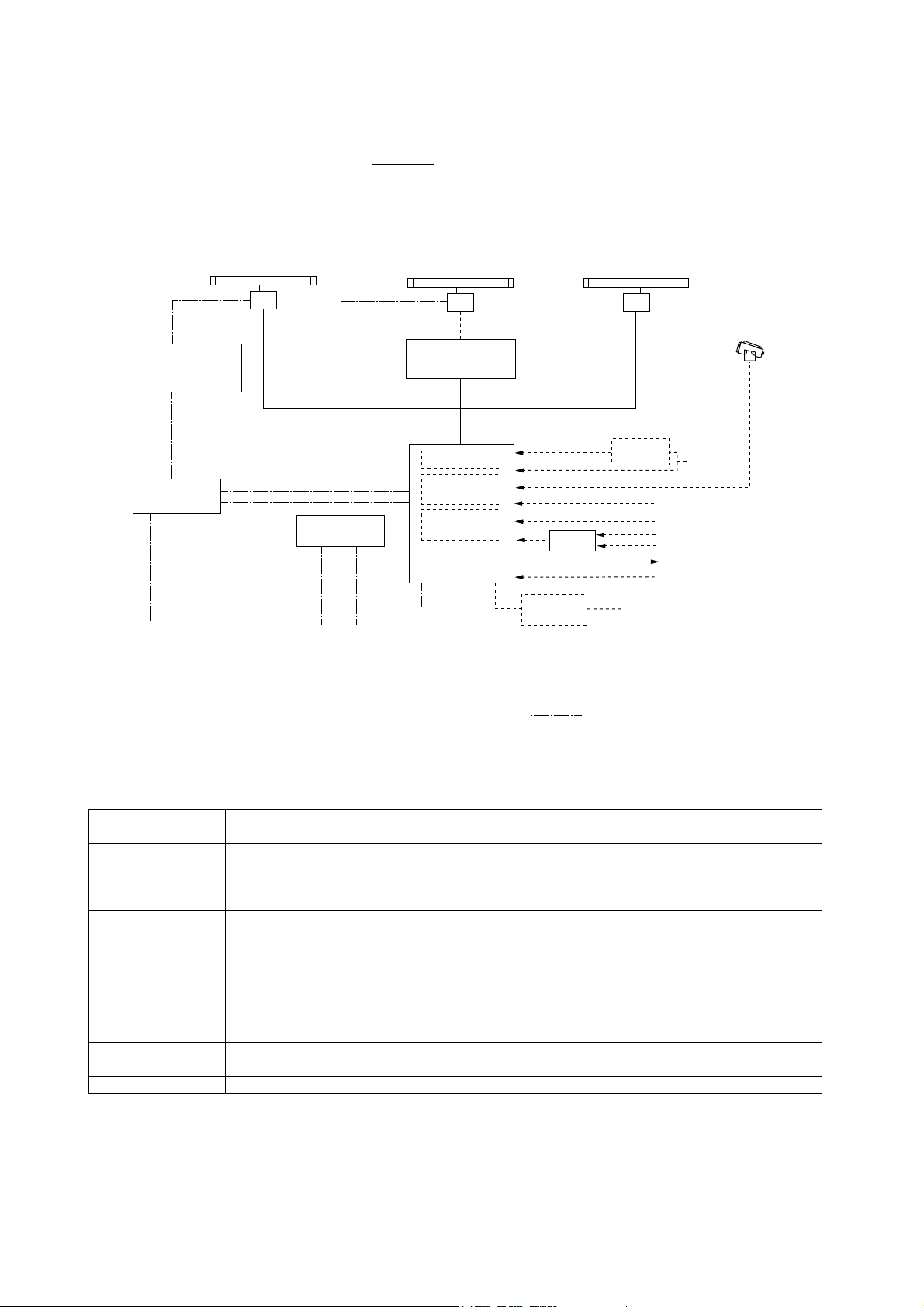
CONFIGURATION OF FR-2105 SERIES RADAR AND ARPA
Your RADAR or ARPA is model FR-21xx
consisting of checked component units. (Check by yourself or your service representative)
FR-2155/2135S/2165DS
ANTENNA UNIT
Power Supply
Unit PSU-001
(For FR-2155/2165DS)
Power Supply
Unit PSU-004
For antenna unit
For display unit
(FR-2155/2165DS)
Display unit
115/230 VAC , 1φ, 50/60Hz
115 VAC , 1φ, 50/60 Hz (FR-2155/2165DS)
Antenna unit
See the table in below
FR-2125W/2135SW
ANTENNA UNIT
Waveguide or
Coax cable
TRANSCEIVER UNIT
For FR-2125W/2135SW
DISPLAY UNIT
RDP-124
Power Supply
Unit PSU-004
For display unit
For antenna unit
115/230 VAC , 1φ, 50/60 Hz
Display unit
115/230 VAC , 1φ, 50/60 Hz (FR-2125W/2135SW)
Antenna unit
See the table in below
(Ant and disp for FR-2115/2125)
Gyro Interface
ARPA board
ARP-26
Video Plotter
RP-26
Please specify power supply when ordering.
Optional transformer is required for other mains.
Interface
IF-2300
Interswitch
FR-2115/2125
ANTENNA UNIT
Gyro
Converter
Other Radar system
Optional Supply
Power
Performance Monitor (option)
PM-30 for X-band
PM-50 for S-band
Gyro
SDME (pulse)
EPFS
SDME (VBW)
GYRO (HDT)
ARPA data (TTM)
External Buzzer
115/230 VAC ,
1φ, 50/60 Hz
ANTENNA UNIT
FR-2115
FR-2115-B
FR-2125
FR-2125-B
FR--2155
FR-2155-B
FR-2125W
FR-2125W-B
FR-2135S
FR-2135S-B
FR-2135SW
FR-2135SW-B
FR-2165DS RSB0051 (21 rpm, 24 VDC): Motor RM-6585
RSB-0074 (24 rpm, 24VDC): Motor D8G-516
RSB-0075 (42 rpm, 24VDC): Motor D8G-571 --- HSC X-band
RSB-0074 (24 rpm, 24VDC): Motor D8G-516
RSB-0075 (42 rpm, 24VDC): Motor D8G-571571 --- HSC X-band
RSB-0049 (16 rpm (50Hz)/20 rpm (60 Hz), 200/220 VAC, 3ø: Motor GOB-8222
RSB-0050 (20 rpm, 24VDC): Motor RM-6585
RSB0076 (21 rpm (50Hz)/26 rpm (60Hz), 200/220 VAC, 3ø): Motor RM-8123
RSB0077 (21 rpm (50Hz)/26 rpm (60Hz), 380/440 VAC, 3ø): Motor RM-8124
RSB0078 (21 rpm (50Hz)/26 rpm (60Hz), 100 VAC, 1ø): Motor RM-8247
RSB0026 (21 rpm (50Hz)/26 rpm (60Hz), 200/220 VAC, 3ø): Motor RM-7398
RSB0031 (21 rpm (50Hz)/26 rpm (60Hz), 380/440 VAC, 3ø): Motor RM-7435
RSB0088(45 rpm, 220 VAC, 3ø 50Hz): Motor RM-9519 --- HSC S-band
RSB0089 (45 rpm, 220 VAC, 3ø 60Hz): Motor RM-9520 --- HSC S-band
RSB0090 (45 rpm, 440 VAC, 3ø 60Hz): Motor RM-9521 --- HSC S-band
RSB0027 (21 rpm (50Hz)/26 rpm (60Hz), 200/220 VAC, 3ø: Motor RM-7398
RSB0032 (21 rpm (50Hz)/26 rpm (60Hz), 380/440 VAC, 3ø: Motor RM-7435
xiv
Page 17
CONFIGURATION OF FR-2105-B SERIES RADAR AND ARPA
Your RADAR or ARPA is model FR-21xx -B
consisting of checked component units. (Check by yourself or your service representative)
FR-2155-B/2135S-B
ANTENNA UNIT
Power Supply
Unit PSU-001
(For FR-2155-B)
Power Supply
Unit PSU-004
For antenna unit
For display unit
(FR-2155-B)
Display unit
115/230 VAC , 1φ, 50/60Hz
115 VAC , 1φ, 50/60 Hz (FR-2155-B)
Antenna unit
200 VAC , 3φ, 50 Hz (FR-2135S-B)
220 VAC , 3φ, 60 Hz (FR-2155-B/2135S-B)
380 VAC , 3φ, 50 Hz (FR-2135S-B)
440 VAC , 3φ, 60 Hz (FR-2135S-B)
FR-2125W-B/2135SW-B
ANTENNA UNIT
Waveguide or
Coax cable
TRANSCEIVER UNIT
For FR-2125W/2135SW
Processor unit
RPU-011
Power Supply
Unit PSU-004
For display unit
For antenna unit
115/230 VAC , 1φ, 50/60 Hz
Display unit
115/230 VAC , 1φ, 50/60 Hz (FR-2125W-B/2135SW-B)
Antenna unit
230 VAC , 1φ, 50/60 Hz (FR-2125W-B)
220 VAC , 3φ, 60 Hz (FR-2135SW-B)
380 VAC , 3φ, 50 Hz (FR-2125W-B/2135SW-B)
440 VAC , 3φ, 60 Hz (FR-2125W-B/2135SW-B)
(Ant and disp for FR-2115-B/2125-B)
Gyro Interface
ARPA board
ARP-26
Video Plotter
RP-26
Please specify power supply when ordering.
Optional transformer is required for other mains.
MONITOR
RDP-124-M-ES
Interface
IF-2300
Interswitch
RJ-7/RJ-8
FR-2115-B/2125-B
ANTENNA UNIT
CONTROL UNIT
RCU-011
Gyro
Converter
SDME (pulse)
EPFS
SDME (VBW)
GYRO (HDT)
ARPA data (TTM)
External Buzzer
Other Radar system
Optional Supply
Power
Performance Monitor (option)
PM-30 for X-band
PM-50 for S-band
Gyro
115/230 VAC ,
1φ, 50/60 Hz
Note: The Display unit RDP-124 for FR-2105 series radar is separated into the Monitor
RDP-124-M-ES, the Processor unit RPU-011 and the Control unit RCU-011 for FR-2105-B
series radar.
xv
Page 18
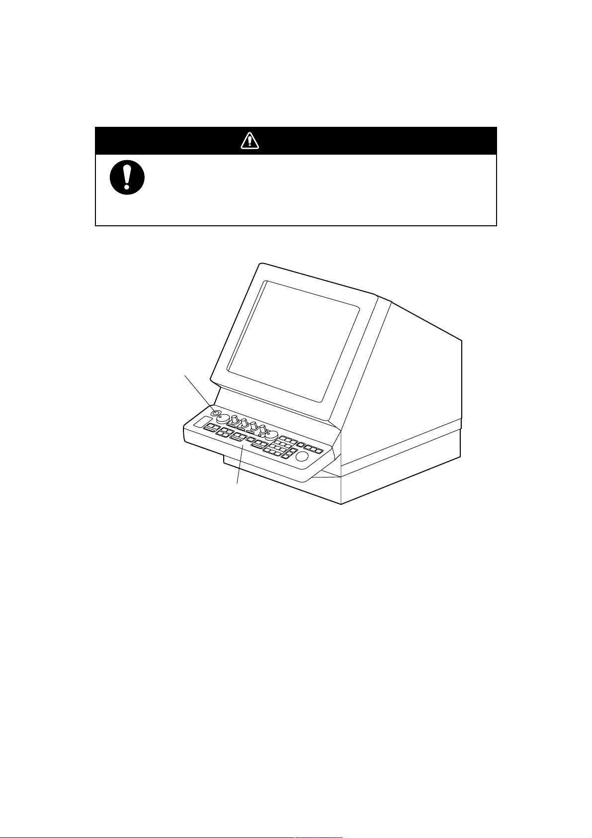
Chapter 1 OPERATION
DANGERDANGER
Before turning on the radar, make sure that there is no one near the
antenna unit.
Serious injury or even death may result if a rotating antenna strikes
someone standing nearby.
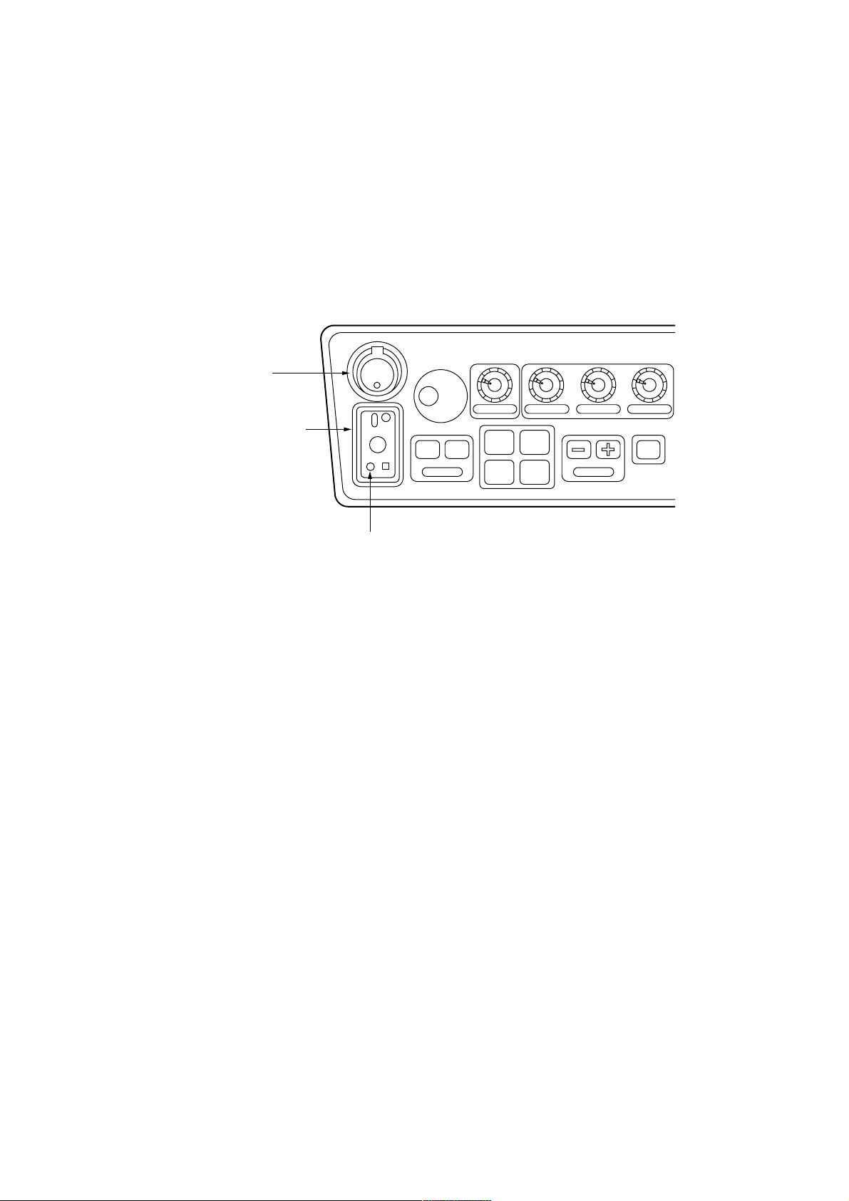
Power switch
Control head
1.1 Turning on the Power
The POWER switch is located at the left corner of the control head. Push it to switch on the
radar system. To turn off the radar, push it again. The screen shows the bearing scale and
digital timer in approximately 15 seconds after power-on. The
minutes of warm-up time. During this period the magnetron, i.e., transmitter tube, is warmed
for transmission. When the timer has reached 0:00, the indication STBY appears indicating
that the radar is now ready to transmit pulses.
In warm-up and standby condition, you will see the message BRG SIG MISSING. This is
normal because a bearing (azimuth) signal is not yet generated when the antenna is not
rotating. ON TIME and TX TIME values shown at the bottom of the screen are the time
counts in hours and tenths of hour when the radar has been powered.
timer counts
down three
-1.
1-
Page 19

1.2 Transmitter ON
When the STANDBY status is displayed on the screen, press the transmit switch labeled
STBY/TX on the control panel of the display unit.
The radar is initially set to previously used range and pulsewidth. Other settings such as
brilliance levels, VRMs, EBLs and menu option selections are also set to previous settings.
The transmit switch toggles the radar between STANDBY and TRANSMIT status. The
antenna stops in STANDBY status and rotates in TRANSMIT status.
Quick Start
Provided that the radar was once in use with the transmitter tube (magnetron) still warm, you
can turn the radar into TRANSMIT condition without 3-minutes standby. If the Power Switch
has been turned off by mistake or the like and you wish to restart the radar promptly, turn on
the Power Switch not later than 10 seconds after power-off.
Notes:
1) If the antenna does not rotate in TRANSMIT status, check whether the antenna switch in
the tuning compartment is in the OFF position.
2) The magnetron ages with time resulting in a reduction of output power. It is highly
recommended that the radar be set to STANDBY status when not used for an extended
period of time.
-1.
2-
Page 20
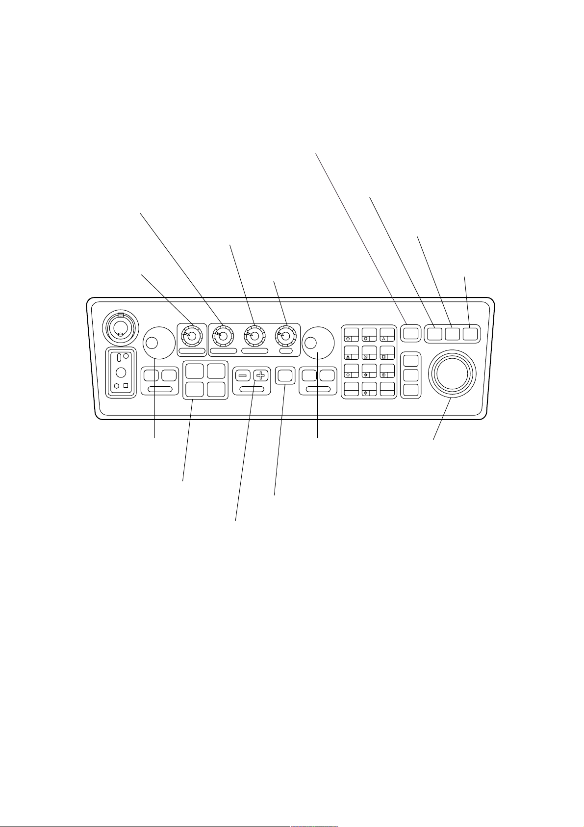
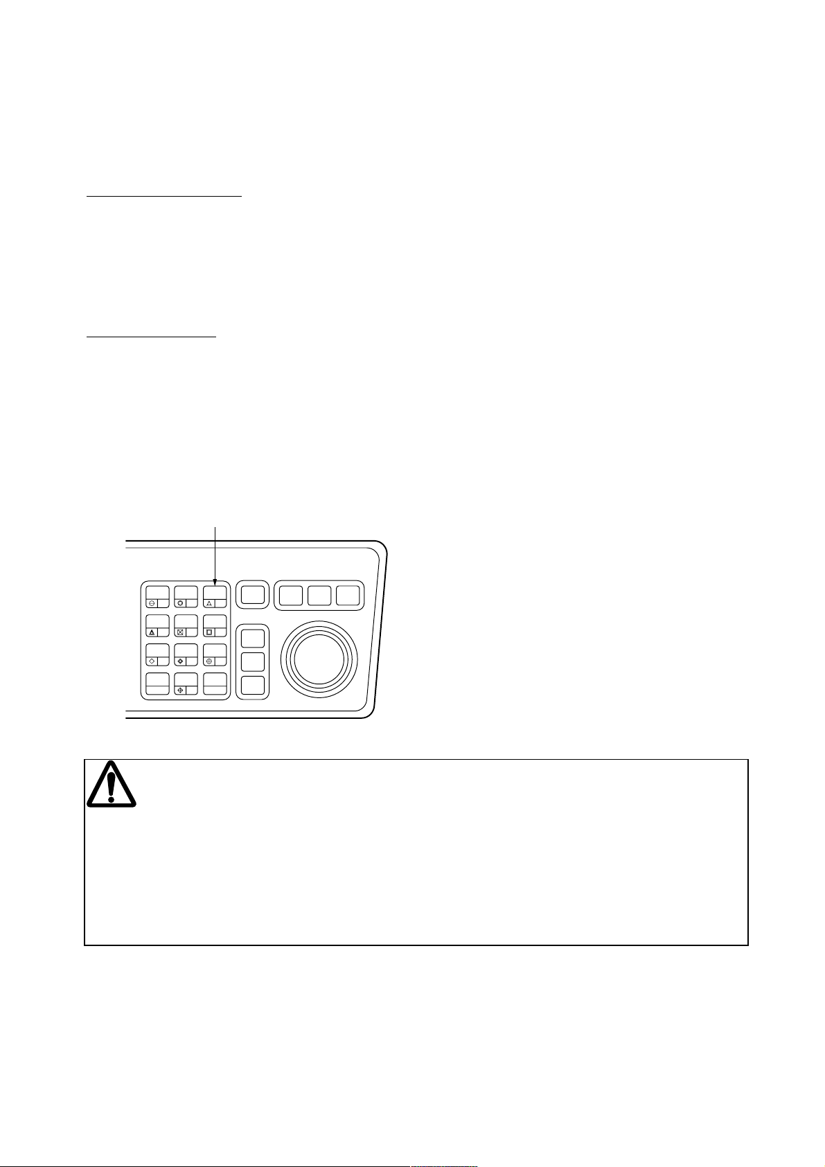
1.3 Control Head
A/C RAIN
Suppresses clutter from
rain, snow, clouds.
BRILLIANCE
Adjusts the brightness
of entire screen.
A/C SEA
Suppresses sea clutter to
improve the short range
discrimination.
GAIN
Adjusts the radar sensitivity.
AUDIO OFF
Acknowledges audible alarms, no effect on
visual alarms.
RADAR MENU
for setting various parameters for
radar operation and radar map.
NAV MENU
Sets parameters for nav info.
PLOT MENU
for plotting
POWER
ON
OFF
PM
ANTENNA
TUNE
DEGAUSS ERROR
OFF ON
EBL
EBL control and on/off keys
Pressing ON key toggles
between NO.1 and NO.2
EBLs.
FUNCTION Keys
#1: Set-up 1
#2: Set-up 2
#3: Set-up 3
#4: Set-up 4
BRILLIANCE A/C RAIN A/C SEA GAIN
#1 #2
#3 #4
RANGE
STBY
TRANSMIT/STANDBY
RANGE Keys
Select the range scales.
HL
PANEL
OFF
BRILL
2
1
OFF
VECTOR
CENTER
4
5
CHART
EBL
ALIGN
7
OFF ON
TX
VRM
TARGET
TRAILS
CANCEL
CU, TM
RESET
8
0
VRM control and on/off keys
Pressing ON key toggles
between NO.1 and NO.2
VRMs.
MODE
AUDIO
RADAR
MENU
PLOT
MENU
LOST
TARGET
MARK
A/C
AUTO
ENTER
OFF
3
6
ACQ
TARGET
9
DATA
TARGET
CANCEL
TRACKBALL
Shifts the cursor for plotting,
entering reference points,
etc.
NAV
MENU
-1.
3-
Page 21
(3)
(2)
(1)
(12)
(4)
(5)
HL
OFF
OFF
CENTER
EBL
OFFSET
TARGET
TRAILS
CANCEL
(11) (6)
1
4
7
PANEL
BRILL
VECTOR
CHART
ALIGN
CU, TM
RESET
2
5
8
0
(14)
MODE
LOST
TARGET
MARK
A/C
AUTO
ENTER
(7),
AUDIO
3
OFF
RADAR
MENU
PLOT
MENU
NAV
MENU
(13)
6
ACQ
9
TARGET
DATA
TARGET
CANCEL
(8)
(9)
(10)
(15)
(16)
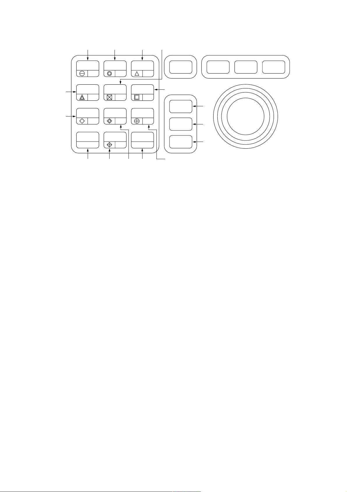
1 MODE Selects presentation modes: Head-up, Head-up TB, North-up, Course-up and True
Motion.
2 PANEL BRILL Adjusts brightness of control panel.
3 HL OFF Temporarily erases the heading line.
4 OFF-CENTER Activates and deactivates off-centering of the own ship position.
5 EBL OFFSET Activates and deactivates off-centering of the EBL origin.
6 C U, TM RESET Resets the heading line to 000° in course-up mode; moves own ship
position to 75% radius in stern direction in the True Motion mode.
7 A/C AUTO Reduces sea clutter at preset level. Permits manual override by A/C SEA and
A/C RAIN controls.
11 TARGET TRAILS CANCEL Erases target trails.
Keys for EPA or ARPA (optional)
8 ACQ key Acquires a target after selecting it by trackball.
9 TARGET DATA Displays the acquired target data for 2 or 3 targets at a time.
10 TARGET CANCEL Terminates plotting of a specified target or all tracked targets.
12 VECTOR Select vector mode; true or relative.
13 LOST TARGET Silences the lost target audible alarm and erases the lost target symbol.
14 CHART ALIGN Aligns chart with the radar display.
15 MARK Enters/erases mark.
16 ENTER Used to save settings on menu screen.
Keys 0-9 Select video plotting symbols. Also used for entering numeric data in any mode as
applicable.
-1.
4-
Page 22
1.4 CRT Brilliance
The BRILLIANCE control on the control head of the display unit adjusts the entire screen
brightness. Note that the optimum point of adjustment varies with ambient light conditions,
especially between daytime and nighttime.
Brilliance
control
BRILLIANCE
A/C RAIN GAINA/C SEA
Note: The CRT brilliance should be adjusted before adjusting relative brilliance levels on the
BRILLIANCE menu to be explained later.
1.5 Tuning the Receiver
Tuning method can be selected at RADAR 3 menu; auto or manual.
1. Press the RADAR MENU key.
2. Press [0], [0], [2], [0] and [0] in sequence to reach the RADAR 3 menu item.
3. Press the [9] key twice to change between Auto and Manual.
4. Press the ENTER key to confirm your selection.
5. Press the RADAR MENU key to close the menu.
Automatic tuning
The radar receiver is tuned automatically each time the power is turned on; thus, there is no
front panel control for tuning. The tuning indicator and the label AUTO TUNE at the top right
corner of the display unit show the tuning circuit is working.
Manual tuning
If you are not satisfied w it h the curr ent tune setti ng, fol l ow these steps to fine-t une the recei ver :
TUNE control
ERROR lamp (See next page.)
1. Set the tuning method to manual as described above.
2. While observing the picture on the 48 mile scale, slowly adjust the TUNE control in the
tune compartment and find the best tuning point.
3. Make sure that the radar has been set to the best tuning point. This condition is where the
tuning indicator lights to about 80% of its total length. Note that the tuning indicator will
never extend to full length.
-1.
5-
Page 23

Video Freeze-up Recovery
Video freeze-up or lock- up can occur unexpect edly on any di git al r aster scan r adar s. T hi s is mainly
caused by heavy spike noise in the power line and can be noticed by carefully watching the nearly
visible sweep line. If you suspect that the picture is not updated every scan of the antenna or no key
entry is accepted notwithstanding the apparently nor mal pi ctur es, do Quick S tar t to r estor e nor mal
operation.
1. Turn off the Power Switch and within 10 seconds turn it on again.
2. Press the Transmit switch labeled STBY/TX for transmit condition.
NOTE: This equipment has self-diagnostic function to check operational software periodically. If
any trouble has been found, the ERROR lamp lights. In this case, do the above procedure.
-1.
6-
Page 24
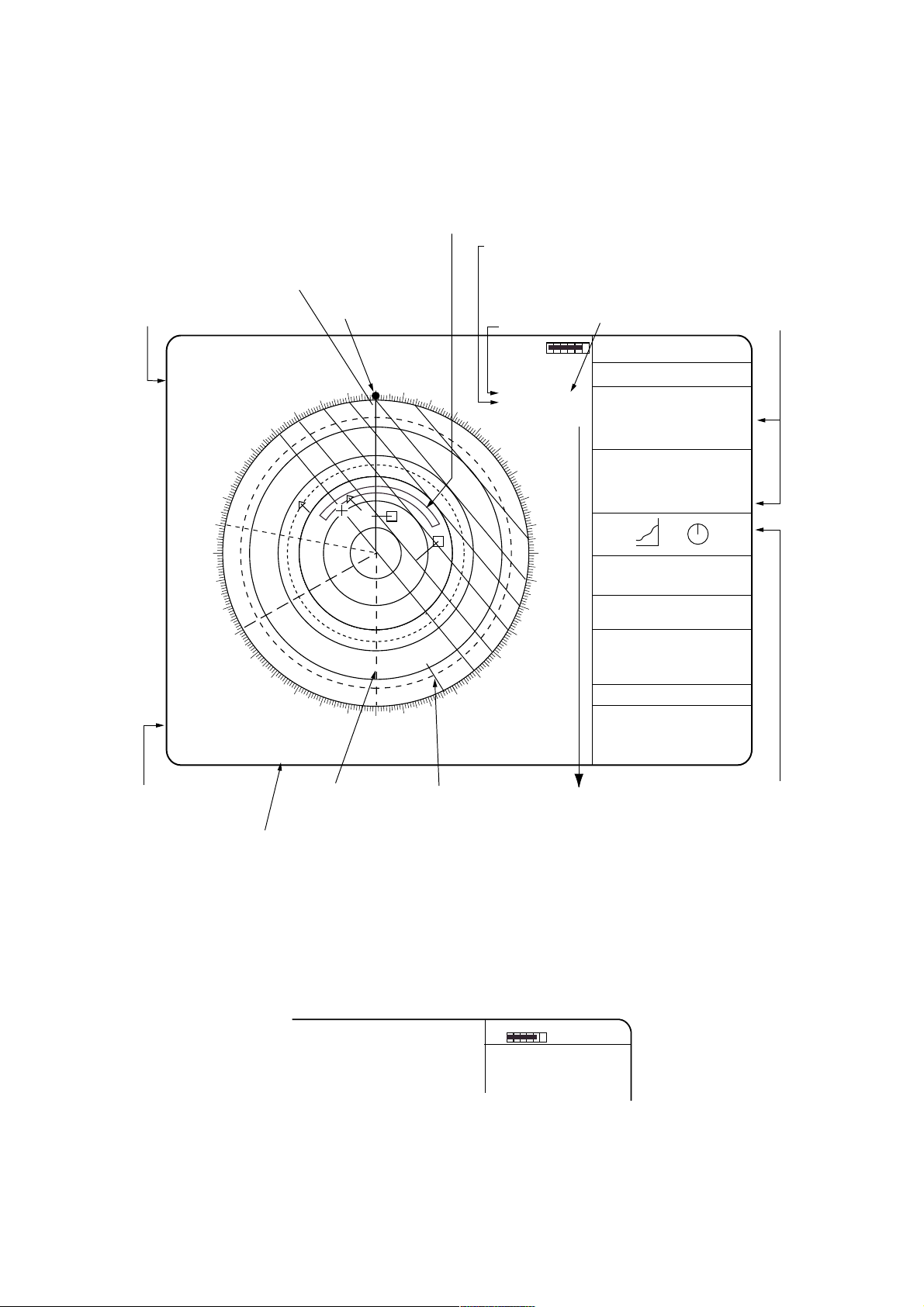
1.6 On-screen Legends and Markers
Target Alarm Zone (Radar) or Guard Zone (ARPA),
1st zone between 3 and 6 nm, 2nd zone anywhere.
Set & Drift values are
accessible on RADAR MENU.
Heading line
Cursor position
from OS
12/
2NM
+ 4.2NM
320.2° R
HEAD UP RM
PULSE 1 M1
EAV 1
IR3
300
ES1
290
280
270
260
250
240
X-Band
A/C AUTO
NOISE
REJ
OFFCENTER
Long-1
EBL
>287.2° R<
240.0° R
330
320
310
230
220
210
INDEX LINE
>140.9° <
Heading marker
000
350
340
200
190
180
010
1
170
020
030
2
150
160
WATCH 11:28
SOG*
AUTO TUNE
Disp 1
ANT 1 MAIN
LOG F 10.0 KT
SOG SB -1.0 KT
SET & DRIFT
MAN ALIGNED
040
050
060
120
130
140
070
110
TRUE TRAIL
3MIN 1:25
TGT ALARM 1
TGT ALARM 2
VRM
>10.75NM<
7.00NM
Dual-axis SDME
F: Fore/aft speed (- sign for reverse).
SB: Port/stbd (-sign for port)
HDG 155.0° T
SPD 12.0KT BT LOG
ARPA AUTO-MAN
TRUE VEC 6MIN GRD STAB
HISTORY 6MIN
RNG 3.5NM
BRG 25.5°R
01 CSE 264.0°T BT TRU
SPD 12.3K BT TRU
CPA 2.9NM
TCPA94MIN
BCR 2.9MIN
BCT 94MIN
RNG 4.7NM
BRG 78.5°R
CSE 264.0°T BT TRU
SPD 12.3K BT TRU
02 CPA 2.9NM
TCPA94MIN
BCR 2.9MIN
BCT 94MIN
0
080
090
100
13:28
20
40
60
80
100
-30 20 10
DEPTH 21.1m
CURRENT 1.2KT
105.7°R
11.3KT
285.6
WPT 2 150.8NM
155.0°T
01 → + 11.7NM
162.5°T
OWN SHIP GPS
34°40.849N
125°18.115E
+ CURSOR POSN
34°39.039N
135°18.303E
12MAR 1998
... SIGNAL MISSING ...
GYRO LOG EPFS TRIGGER
VIDEO AZIMUTH HEAD LINE
... ARPA ALARM ...
COLLISION GUARD LOST
TARGET FULL (AUTO + MAN)
Target Data
N
WE
S
Function key
selected
Stern marker
North marker
Manual chart
alignment
This cell indicates 3rd target
data or wind/depth data.
Orientation of Parallel Index Lines
*:With the serial speed inputs and SOG selection, if the type of data is changed from SOG to
STW, the label SOG appears in red at the upper right corner on the screen.
Note: For W-type (Washington Ferry), ship's heading and speed are indicated as follows.
HDG 18.5° GYRO
SPEED 3.5KT BT NAV
ANT 1 MAIN
AUTO TUNE
-1.
7-
Page 25
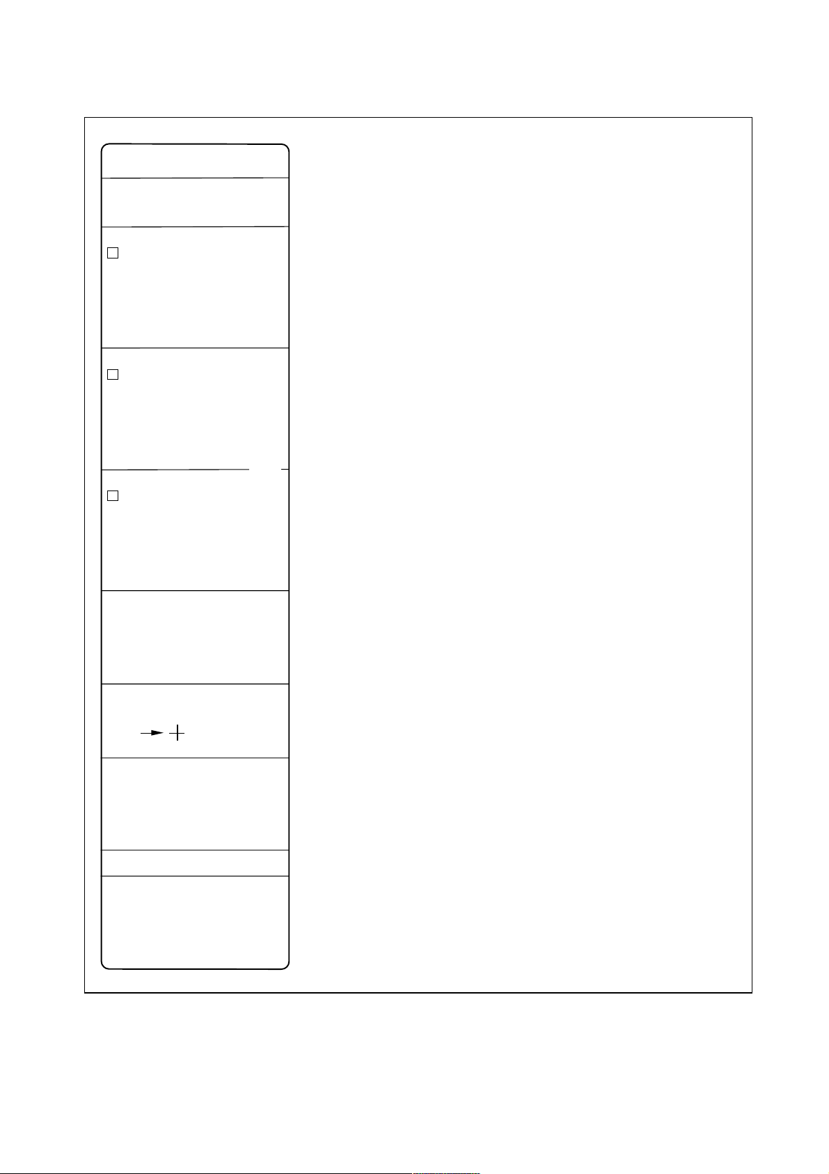
DATA DISPLAY
HDG 155.0 T
SPEED 12.0KT BT LOG
ARPA AUTO+MAN
*
TRUE VEC 6MIN GRD STAB
HISTORY 6MIN
RNG 4.7NM
01
BRG 25.5 T
CSE 264.0 T BT TRU
SPD 12.3KT BT TRU
CPA 3.4NM
TCPA 94MIN
BCR 2.9NM
BCT 94NM
RNG 2.0NM
02
BRG 180.0 T
CSE 200.0 T BT TRU
SPD 10.5KT BT TRU
CPA 1.3NM
TCPA 15.1MIN
BCR 3.0NM
BCT 25NM
RNG 2.0NM
03
BRG 180.0 T
CSE 200.0 T BT TRU
SPD 10.5KT BT TRU
CPA 1.3NM
TCPA 15.1MIN
BCR 3.0NM
BCT 25NM
1:23
HDG: Heading T (True = corrected gyro or magnetic heading)
Speed data is LOG, MAN etc. showing sensor and types.
When set/drift is manually applied, BT appears instead of WT.
(WT: Water tracking mode, BT: Bottom Tracking mode)
SEA STAB: Sea stabilization, displayed objects subject to water,
current.
GND STAB: Ground stabilization, compensated for the current;
stationary objects appear stationary on the display.
Target NO. 01 - 40 in ARPA, 01 - 10 in EPA, automatically assigned.
The numbers are left occupied if targets are lost or intentionally
removed until the full numbers are used up.
Interpreting Course Ex. 180.0 T BT TRU
T: True, referenced to True North
BT: Bottom tracking (referenced on the bottom)
TRU: Vector orientation
Numerals on division lines Ex. 1:23: Elapsed time since last plot (EPA
only)
This third target data area may be used to indicate the graphics of wind
and depth data if the third target data is not interested.
DEPTH 21.1m
CURRENT
WIND
WPT 2 150.8NM
155.0 T
01
OWN SHIP [GP]
34 40.849N
125 18.115E
+CURSOR POSN
34 39.039N
135 18.303E
12 MAR 1998 13:28 LOCAL
... SIGNAL MISSING ...
GYRO LOG EPFS TRIGGER
VIDEO AZIMUTH HEAD LINE
.... ARPA ALARM ....
COLLISION GUARD LOST
TARGET FULL (AUTO + MAN)
2.2KT
105.7 T
11.3KT
285.6 T
11.7NM
162.5 T
This display cell shows digital readouts of water depth, ocean currents,
wind if associated sensors are in use.
Bearing and range to waypoint
Bearing and range from origin mark to cursor.
Electronic Position-Fixing System, such as GPS, DGPS, DECCA,
LORAN C. Status (Healthy or invalid) will be indicated.
Date and time.
Warning and indications
*Note: When a presentation mode other than north-up true motion is
selected in true vector mode, TRUE VEC indication appears in
red to alert you.
-1.
8-
Page 26
1.7 Degaussing the CRT Screen
Each time the radar is turned on, the degaussing circuit automatically demagnetizes the CRT
screen to eliminate color contamination caused by earth's magnetism or magnetized ship
structure.
The screen is also degaussed automatically at certain time intervals. While being degaussed,
the screen may be disturbed momentarily with vertical lines. If you wish to degauss by manual
operation, open the tuning compartment and press the Degauss switch.
POWER switch
Tuning compartment
POWER
ON
PM
ANTENNA
TUNE
DEGAUSS ERR
OFF ON
EBL
BRILLIANCE
#1 #2
#3 #4
A/C RAIN A/C SEA GAIN
STBY
TX
RANGE
DEGAUSS SWITCH
1.8 Initializing the Gyro Readout
With a gyrocompass interfaced with the radar, ship's heading is displayed at the top of the
screen. Upon turning on the radar, align the on-screen GYRO readout with the gyrocompass
reading by the procedure shown below. Once you have set the initial heading correctly,
resetting is not usually required. However, if the GYRO readout goes wrong for some reason,
repeat the procedure to correct it.
1. Press the RADAR MENU key to display the FUNCTIONS 1 menu.
2. Press the [0] key twice to display the FUNCTIONS 3 menu.
3. Press the [9] key to select GYRO SETTING option.
4. Rotate the EBL control to adjust the gyrocompass reading.
5. Press the ENTER key to confirm the setting.
-1.
9-
Page 27
1.9 Presentation Modes
This radar has the following presentation modes:
Relative Motion (RM)
Head-up: Unstabilised
Head-up TB: Head-up with compass-stabilized bearing scale (True Bearing) where the
bearing scale rotates with the compass reading.
Course-up: Compass-stabilized relative to ship's intended course
North-up: Compass-stabilized with reference to north
True Motion (TM)
North-up: Ground or sea stabilized with compass and speed inputs
Selecting presentation mode
Press the MODE key on the control head. Each time the MODE key is pressed, the
presentation mode and mode indication at the upper-left corner of the screen change
cyclically.
MODE key
HL
PANEL
MODE
OFF
OFF
CENTER
EBL
TARGET
TRAILS
CANCEL
AUDIO
BRILL
2
ALIGN
3
LOST
TARGET
5
6
MARK
8
9
A/C
AUTO
0
ENTER
1
VECTOR
4
CHART
7
CU, TM
RESET
OFF
ACQ
TARGET
DATA
TARGET
CANCEL
RADAR
MENU
PLOT
MENU
NAV
MENU
Loss of Gyrocompass signal
When the compass signal is lost, the presentation mode autom at ically becomes head-up and the
HDG (heading) readout at the top of the text area shows asterisks ***. Also GYRO appears in
red characters at the lower right corner on t he scr een. When the gyrocompass signal is restored,
the SET HDG appears at the upper-right corner on the screen. Press the MODE key, and the
asterisks and GYRO go off. Align the HDG readout with the gyrocompass reading, referring to
the previous section 1.8. Finally press the CANCEL key to erase the m essage SET HDG .
10-
-1.
Page 28
Presentation mode,
representati ve display
Description
North marker
310
300
290
280
270
260
250
240
230
220
North marker
320
310
300
290
280
270
260
250
240
230
220
320
210
330
210
330
340
200
200
340
350
190
350
190
Heading Marker
000
010
020
160
170
180
Heading Marker
000
010
020
160
170
180
Heading Line
030
040
050
060
120
130
140
150
Heading Line
030
040
050
060
120
130
140
150
070
110
070
110
080
100
090
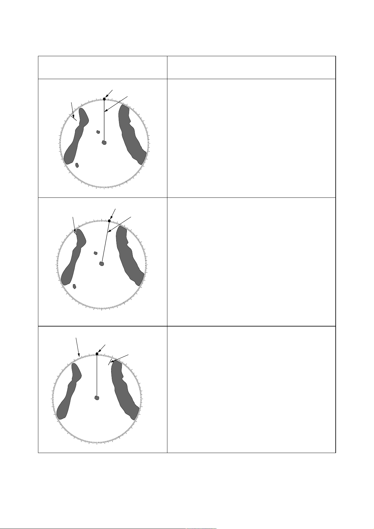
Head-up mode
A display wit hout azimuth stabilization in which the line
connecting the cent er with the top of the display indicates
own ship’s heading.
The tar get pips are painted at their m easured distances
080
090
100
and in their directions r elative to own ship’s heading.
A shore line on t he bear ing s c ale is the north marker
indicating compass nor th. A failure of the compass input
will cause the north marker to disappear and the r eadout
to show asterisks (***.*) and the message GY RO appears
in red at the lower-right corner of t he screen.
Course-up mode
An azimut h s tabilized display in which a line connecting
the center with the top of the display indic ates own ship’s
intended course (namely, own ship’s previous heading just
before this mode has been selected).
Target pips are painted at their measured distances and in
their directions r elative to the intended course which is
maintained at the 0-degr ee pos ition while the heading line
moves in accordance wit h s hip’s y awing and c ourse
change. This mode is useful to avoid smearing of picture
during course change. A fter a course change, pr es s the
[CU, TM RESET] key to reset the picture orientation i f you
wish to continue using t he c ourse-up mode. The heading
line gets back to scale zero.
earing scale rotates with a compass signal
Heading Marker
340
350
250
240
260
270
230
280
220
290
210
300
200
190
310
180
320
330
170
160
150
140
000
North marker
010
020
030
110
120
130
040
050
060
070
080
090
100
Head-up TB (True Bearing) mode
Radar echoes are s hown in the same way as in the
head-up mode. The difference from norm al head- up
presentation lies in t he orientation of the bear ing s c ale.
The bearing scale is compass stabilized. That is, it rotates
in accordance with the c ompass signal, enabling you to
know own ship’s heading at a glance.
This mode is av ailable only when the radar is interfac ed
with a gyrocompass.
If the compass fails, the bearing scale returns to the state
of head-up mode.
-1.
11-
Page 29
Presentation mode,
representative display
270
260
280
290
250
300
240
310
230
320
220
210
330
340
200
350
190
North
000
180
010
170
Heading Line
020
030
040
050
130
140
150
160
Heading
Marker
060
070
080
090
100
110
120
270
260
280
290
250
300
240
310
230
320
220
210
330
340
200
350
190
North
000
180
Heading Line
010
020
030
150
160
170
040
140
Heading
Marker
050
060
070
110
120
130
080
090
100
Description
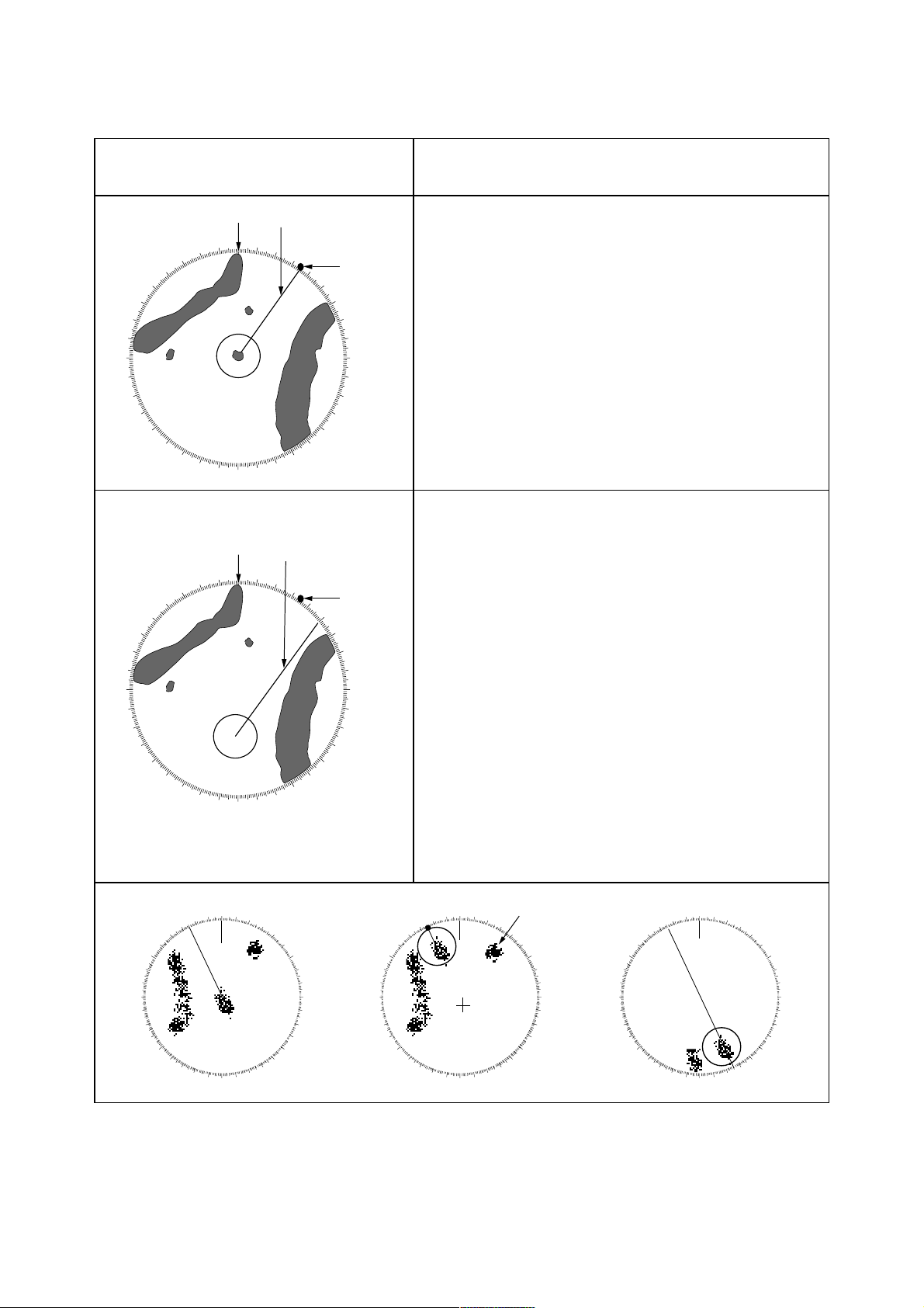
North-up mode
In the north-up mode, target pips are painted at their
measured distances and in their true (compass) directions
from own ship, north bearing maintained up of the screen.
The heading line changes its direction according to the
ship’s heading.
If the gyrocompass fails, the presentation mode changes
to head-up and the north marker disappears. Also, the
HDG readout shows asterisks (***.*) And the message
GYRO appears in red at the lower-right corner of the
screen.
True motion mode
Own ship and other moving objects move in accordance
with their true courses and speed. In ground stabilized
TM, all fixed targets, such as landmasses, appear as
stationary echoes. In the sea stabilized TM without set
and drift inputs, the landmass can move on the screen.
When own ship reaches a point corresponding to 75% of
the radius of the display, it is automatically reset to a point
of 75% radius opposite to the extension of the heading
marker passing through the display center. Resetting can
be made at any moment before the ship reaches the limit
by pressing the [CU, TM reset]. Automatic resetting is
preceded by a beep sound.
If the compass fails, the mode is changed to the head-up
and the north marker disappears. The HDG readout
shows asterisks (***.*) and the message GYRO appears
in red at the lower-right corner of the screen.
000 010
350
340
330
320
310
300
290
280
270
260
250
240
230
220
210
200
020
030
040
050
060
070
080
090
100
110
120
130
140
150
160
170180190
320
310
300
290
280
270
260
250
240
230
220
000 010
350
340
330
210
200
020
Target trail
030
040
050
060
070
080
090
100
110
120
130
140
150
160
170180190
(a) True motion Is selected (b) Own ship has reached a
point 75% of display radius
12-
-1.
000 010
350
340
330
320
310
300
290
280
270
260
250
240
230
220
210
200
020
030
040
050
060
070
080
090
100
110
120
130
140
150
160
170180190
(c) own ship is automatically
reset to 75% of radius
Page 30

1.10 Selecting the Range Scale
The display range scale is changed by pressing the [+] and [-] keys. The selected range scale
and range ring interval are shown at the upper left corner on the screen. When a target of
interest comes closer, reduce the range scale so that it appears in 50 - 90 % of the display
radius. The range scales are:
0.125−0.25−0.5−0.75−1.5−3−6−12−24−48−96 nm (IMO-type)
(Maximum range for Regular type or Japanese version is 72 nm for FR-2115/2115-B or 120
nm for other models)
1.11 Selecting the Pulsel ength
The pulselength in use is displayed at the upper-left position of the screen using the
abbreviations shown in the table below.
Appropriate pulselengths are preset to individual range scales and function keys. Therefore,
you are not usually required to select them. If you are not satisfied with the current pulselength
settings, however, it is possible to change them by the Radar menu operation shown below.
You can choose the pulselength 1 or 2 on the scales 0.5 to 24 nm ranges on FR-2115/2125
models (0.75 to 24 nm ranges on the other models).
Selecting pulsel engt h 1 or 2
1. Press the RADAR MENU key to display the FUNCTIONS 1 menu.
2. Press the [6] key to select PULSELENGTH 1 or 2 as appropriate.
3. Press the RADAR MENU key to close the FUNCTIONS menu.
LABEL P/L in FR-2115/2125/
2115-B/2125-B
S (Short pulse) - 0.08 µs
S1 (Short pulse 1) 0.07 µs S2 (Short pulse 2) 0.15 µs M1 (Medium pulse 1) 0.3 µs 0.3 µs (0.2 µs in F R - 2155, 2165DS)
M2 (Medium pulse 2) 0.5 µs 0.6 µs
M3 (Medium pulse 3) 0.7 µs -
P/L in other models
L (Long pulse) 1.2 µs 1.2 µs
-1.
13-
Page 31

Presetting pulselengths 1 and 2
Pulselength 1 and 2 can be preset on the PULSE WD 1 and 2 menus. Shown below are
examples of the pulselength setup procedure:
1. To enable selection of S1 (0.07 µs) and S2 (0.15 µs) pulselength on the 0.5 nm range on
FR-2115/2125/2115-B/2125-B model, select S1 at 0.5 nm on the PULSE WD 1 menu and
S2 at 0.5 nm on the PULSELENGTH 2 menu.
2. To enable selection of S2 (0.15 µs) and M1 (0.3 µs) pulselength on the 3 nm range on
FR-2115/2125/2115-B/2125-B model, select S2 at 3 nm in the PULSE WD 1 menu and
M1 at 3 nm in the PULSE WD 2 menu.
A longer pulse provides an increased detection range, but with reduced discrimination. If you
need discrimination in preference to detection, choose a shorter pulse.
Example: To select S1 (0.07 µs) as Pulselength 1 for the 0.5 nm range, display the
PULSELENGTH 1 menu following the steps shown above and hit the [2] key to choose "0.5
NM." Further hit the [2] key until the menu option "S1" is highlighted to the right of "0.5
NM."
-1.
14-
Page 32

[RADAR MENU] key
[FUNCTIONS 1]
1 TARGET TRAILS
2 TARGET ALARM 1 or 2
3 ORIGIN MARK 1 to 10
4 INDEX LINES
5 ZOOM*
6 PULSE WIDTH
7 INT REJECT
8 ARPA
9 VIDEO PLOT
0 [FUNCTION 2]
[0] key [1] key
[FUNCTIONS 2]
1 [FUNCTIONS 1]
2 BKGD COLOR BLK(GRN CHAR)/
BLK(RED CHAR)/
BLU (ECHO AREA)
BLU/
BRT BLU
3 ECHO STRETCH OFF/1/2 / 3
4 ECHO AVERAGE OFF/1/2/3
5 ECHO COLOR YEL/GRN/ COLOR*
6 SHIP SPEED LOG/NAV*/MAN
MAN = xx.xKT
(STW/SOG)
7 SET, DRIFT OFF/MAN
SET = xxx.x°
DRIFT = xx.xKT
8 INDEX LINES NO. 2 VRM/MAN
MAN = xx.xx NM
9 BRILLIANCE (1)
0 [FUNCTION 3]
*: R-type only
*1: Fishing mode only (one type of R-type)
[0] key [1] key
[FUNCTIONS 3]
1 [FUNCTIONS 2]
2 [RADAR 1]
3 [FUNCTION KEY 1]
4 [FUNCTION KEY 2]
5 [FUNCTION KEY 3]
6 [FUNCTION KEY 4]
7 RADAR* 1/2
7 INTER SWITCH
8
9 GYRO SETTING EBL = xxx.x°
0 [FUNCTIONS 4]
[2]
[RADAR 1]
1 [FUNCTIONS 3]
2 EBL 1 * REL/TRUE
3 EBL 2 * REL/TRUE
4 VRM 1 *1 NM/km (IMO: nm only)
5 VRM 2 *1 NM/km (IMO: nm only)
6 TRAIL REL/TRUE
7 TRAIL GRAD SGL/MULT
8 [PULSE WD 1]
9 [PULSE WD 2]
0 [RADAR 2]
In RADAR 1 menu, select 8 for pulselength 1 or 9 for pulselength 2. Selection available is as
below for FR-2115/2125/2115-B/2125-B:
0.5 nm range S1/S2 0.75 nm range S1/S2/M1
1.5 nm range S1/S2/M1 3 nm range S2/M1/M2/M3
6 nm range M1/M2/M3/L 12-24 nm range M2/M3/L
-1.15-
Page 33

1.12 Adjusting the Sensitivity
The GAIN control is used to adjust the sensitivity of the receiver, and thus the intensity of
echoes as they appear on the screen. It should be adjusted so that speckled background noise
is just visible on the screen.
To become acquainted with the way the GAIN control works, try rotating it between fully
counterclockwise and clockwise positions while observing the radar picture. You will notice
that clockwise rotation increases the echo intensity level. A low gain setting results in the loss
of weak echoes and a reduced detection range. If you turn the GAIN control too far clockwise
for an excessive gain setting, desired echoes will be masked in the strong background noise.
GAIN CONTROL
POWER
A/C RAIN A/C SEA GAIN
#1 #2
#3 #4
RANGE
STBY
TX
ON
PM
ANTENNA
TUNE
DEGAUSS ERR
BRILLIANCE
OFF ON
EBL
1.13 Suppressing Sea Clutter
In rough weather conditions returns from the sea surface are received over several miles
around own ship and mask close targets. This situation can be improved by properly adjusting
the A/C SEA (Anti-Clutter Sea) control.
A/C SEA CONTROL
BRILLIANCE
OFF ON
EBL
A/C RAIN A/C SEA GAIN
#1 #2
#3 #4
RANGE
STBY
TX
A/C SEA control
off
A/C SEA control
adjusted
-1.16-
Page 34

Automatic anti-clutter control
The easiest way to suppress the surface clutter
is to use the automatic control. Press the A/C
AUTO key. Use of a function key is also a
good method for reducing sea clutter. For this
purpose, presetting is required. Consult a
FURUNO representative.
CAUTION
The auto A/C function can erase weak target echoes.
Manual anti-clutter control
HL
OFF
OFF
CENTER
EBL
TARGET
TRAILS
CANCEL
PANEL
BRILL
2
1
VECTOR
4
5
CHART
ALIGN
7
8
CU, TM
RESET
0
A/C AUTO key
MODE
LOST
TARGET
MARK
A/C
AUTO
ENTER
AUDIO
RADAR
OFF
3
6
TARGET
9
TARGET
CANCEL
MENU
AC
DATA
PLOT
MENU
NAV
MENU
From the fully counterclockwise position, slowly turn the A/C SEA control clockwise. For
optimum target detection, you should leave speckles of the surface return slightly visible.
The anti-clutter sea control is often referred to as STC (Sensitivity Time Control) which
decreases the amplification of the receiver immediately after a radar pulse is transmitted, and
progressively increases the sensitivity as the range increases.
A common mistake is to over-adjust the A/C SEA control so that the surface clutter is
completely removed. By rotating the control fully clockwise, you will see how dangerous this
can be; a dark zone is created near the center of the screen and close-in targets can be lost.
This dark zone is even more dangerous if the gain has not been properly adjusted. Always
leave a little surface clutter visible on the screen. If no surface clutter is observed (on a very
calm water), set the control at the fully counterclockwise position.
-1.17-
Page 35

1.14 Suppressing Precipitati on Cl utter
In adverse weather conditions, clouds, rain or snow produce a lot of spray-like spurious
echoes and impairs target detection over a long distance. This situation can be improved by
using a function key provided that it is so programmed. If the function key fails to offer a
favorable suppression of the rain clutter, adjust the A/C RAIN control on the front control
head.
A/C RAIN CONTROL
BRILLIANCE
OFF ON
EBL
A/C RAIN A/C SEA GAIN
12
34
RANGE
STBY
TX
A/C RAIN control
OFF
A/C RAIN control
adjusted
The A/C RAIN control adjusts the receiver sensitivity as the A/C SEA control does but rather
in a longer time period (longer range). Clockwise rotation of this control increases the anticlutter effect.
1.15 Interference Rejector
Mutual radar interference may occur in the vicinity of another
shipborne radar operating in the same frequency band (9 GHz for
X-band, 3 GHz for S-band). It is seen on the screen as a number of
bright spikes either in irregular patterns or in the form of usually
curved spoke-like dotted lines extending from the center to the edge
of the picture. This type of interference can be reduced by activating
the interference rejector circuit.
The interference rejector is a kind of signal correlation circuit. It
compares the received signals over successive transmissions and
suppresses randomly occurring signals. There are three levels of
interference rejection depending on the number of transmissions that
are correlated. These are indicated by the legends IR1, IR2 and IR3
at the upper-left position of the screen.
-1.18-
Radar interference
Page 36

To activate the interference rejector;
1. Press the RADAR MENU key. The following appears.
[FUNCTIONS 1]
1 TARGET TRAILS
2 TARGET ALARM 1 or 2
3 ORIGIN MARK 1 to 10
4 INDEX LINES
5
6 PULSE WIDTH
7 INT REJECT
8 ARPA
9 VIDEO PLOT
0 [FUNCTION 2]
2. Press the [7] key to select the INT REJECT option.
3. Successive presses of the key increase the effect of interference rejection, up to level 3. A
fourth press deactivates the interference rejector. Switch off the interference rejector when
no interference exists; otherwise weak targets may be lost.
Note: For stable reception of certain types of radar beacons (Racons) or SART (Search and
Rescue Radar Transponder) as required by SOLAS 1974 as amended 1988 (GMDSS), it is
recommended to turn the interference rejector off.
1.16 Measuring the Range
Use the fixed range rings to obtain a rough estimate of the range to a target. They are
concentric solid circles about own ship, or the sweep origin. The number of rings is
automatically determined by the selected range scale and their interval is displayed at the
upper-left position of the screen.
Procedure
1. Press the RADAR MENU key to display FUNCTIONS 1 menu.
2. Press the [0] key to display FUNCTIONS 2 menu.
3. Press [9] key to display BRILLIANCE 1 menu.
1 [FUNCTIONS 2]
2 RINGS BRILL OFF/DIM/M1/M2/BRT
3 EBL BRILL DIM/M1/M2/BRT
4 VRM BRILL DIM/M1/M2/BRT
5 +CURSOR BRILL OFF/DIM/M1/M2/BRT
6 CHAR BRILL DIM/M1/M2/BRT
7 MARK BRILL DIM/M1/M2/BRT
8 TRAIL BRILL DIM/M1/M2/BRT
9 HL BRILL DIM/M/BRT
0 [BRILLIANCE 2]
[BRILLIANCE 1]
-1.19-
Page 37

4. Press [2] key to select RINGS BRILL option.
5. Press [2] key again. Each pressing gradually increase their brightness in 4 steps and fifth
press erases the range rings.
6. Press the ENTER key to confirm you selection.
7. Press the RADAR MENU key to close the menu.
Use the Variable Range Markers (VRMs) for more accurate measurement of the range to a
target. There are two VRMs, No. 1 and No. 2, which appear as dashed rings so that you can
discriminate them from the fixed range rings. The two VRMs can be distinguished from each
other by different lengths of dashes.
000
010
350
340
No.1
VRM
290
280
270
260
250
330
320
310
300
240
230
220
210
200
190
Active VRM is identified
with this marker.
020
030
150
160
170
180
040
050
120
130
140
VRM
0.66NM
1.18NM
Target
blip
060
070
080
100
110
090
No.2
VRM
Measuring the range
Press the VRM ON key to display either of the VRMs.
Successive presses of the VRM ON key toggle the active VRM between No. 1 and No. 2 and
the currently active VRM readout is circumscribed by >.....<.
Turning the VRM control, align the active variable range marker with the inner edge of the
target of interest and read its distance at the lower-right corner of the screen. Each VRM
remains at the same geographical distance when you operate the RANGE+ or RANGE- key.
This means that the apparent radius of the VRM ring changes in proportion to the selected
range scale.
Press the VRM OFF key to key to erase each VRM.
-1.20-
Page 38

1.17 Measuring the Bearing
Use the Electronic Bearing Lines (EBLs) to take bearings of a target. There are two EBLs, No.
1 and No. 2, which are toggled by successive presses of the EBL ON key. Each EBL is a
straight dashed line extending out from the own ship position up to the circumference of the
radar picture. The fine dashed line is the No. 1 EBL and the coarse dashed one is the No. 2
EBL.
Press the EBL ON key to display either of the EBLs.
Successive presses of the EBL ON key toggle the active EBL between No. 1 and No. 2 and
the currently active EBL readout is circumscribed by >... <.
Rotate the EBL rotary control clockwise or counterclockwise until the active EBL bisects the
target of interest, and read its bearing at the lower-left corner of the screen.
The EBL readout is affixed by "R" (relative) if it is relative to own ship's heading, "T" (true) if
it is referenced to the north, as determined by RADAR 2 menu settings.
Each EBL carries a range marker, or a short line crossing the EBL at right angles and its
distance from the EBL origin is indicated at the VRM readout whether or not the
corresponding VRM is displayed. The range marker changes its position along the EBL with
the rotation of the VRM control.
Press the EBL OFF key to erase each EBL.
No.2
EBL
330
320
310
300
290
280
270
260
250
240
EBL
32.5°T
298.0°T
Range scale
markers on EBLs
230
220
210
Active EBL is indicated
with this marker.
000
010
350
340
200
190
020
030
040
140
150
160
170
180
Target
blip
050
060
070
080
090
100
110
120
130
VRM
0.97NM
1.11NM
No.1
EBL
-1.21-
Page 39

1.18 Collision Assessment by Offset EBL
The origin of the EBL can be placed anywhere with the trackball to enable measurement of
range and bearing between any targets. This function is also useful for assessment of the
potential risk of collision. To assess possibility of collision:
1. Press the EBL ON key to display or activate an EBL (No. 1 or 2).
2. Place the cursor (+) on a target appearing as threatening (A in the illustrated example) by
operating the trackball.
3. Press the EBL OFFSET key on the mode panel, and the origin of the active EBL shifts to
the cursor position. Press the EBL OFFSET key again to anchor the EBL origin.
4. After waiting for a few minutes (at least 3 minutes), operate the EBL control until the EBL
bisects the target at the new position (A'). The EBL readout shows the target ship's course,
which may be true or relative depending on the settings on the RADAR 1 menu.
If relative motion is selected, it is also possible to read CPA (Closest Point of Approach) by
using a VRM as shown below (Figure (a)). If the EBL passes through the sweep origin
(own ship) as illustrated (Figure (b)), the target ship is on a collision course.
5. To return the EBL origin to the own ship's position, press the EBL OFFSET key again.
000
010
330
210
350
340
A
1
A
200
190
180
170
160
020
030
150
040
140
050
060
070
080
090
100
110
120
130
VRM
> 0.00 NM<
300
290
280
270
260
250
240
EBL 1
EBL
> 150.3°R<
310
230
320
220
000
010
350
340
330
A
1
A
210
200
190
170
180
020
160
030
150
040
140
VRM 1
050
060
070
110
120
130
VRM
>3.85 NM<
080
100
090
300
290
280
270
260
250
240
EBL 1
EBL
> 150.3°R<
320
310
230
220
(a) Evaluating the target ship course in RM (b) Target ship on collision course
-1.22-
Page 40

1.19 Measuring Range and Bearing Between Two Targets
Press the EBL OFFSET key, and place the origin of No. 1 EBL, for example, on a target of
interest (target 1 in the illustrated example) by operating the trackball.
Turn the EBL control until the EBL passes through another target of interest (target 2).
Turn the VRM control until the range marker aligns with target 2. The active VRM readout at
the lower-right corner of the screen indicates the distance between the two targets.
You can repeat the same procedure on third and forth targets (targets 3 and 4) by using No. 2
EBL and No. 2 VRM.
Bearing is shown relative to own ship with suffix "R" or as a true bearing with suffix "T"
depending on EBL relative/true settings on the RADAR 1 menu. To return the EBL origin to
the own ship position, press the EBL OFFSET key again.
040
R2
Target 3
130
140
VRM
> 0.50NM<
No.2
EBL
050
060
070
110
120
0.98NM
Range
marker
080
090
100
No.1 VRM
No.2 VRM
No.1
EBL
EBL
> 140.0°R<
335.2°R
Range
marker
310
300
290
280
270
260
250
240
320
EBL
origin
230
220
340
330
Target 1
210
200
000
350
Target 2
R1
190
180
010
020
Target 4
R2
160
170
030
150
Range/bearing
between targets
1 and 2
Range/bearing
between targets
3 and 4
1.20 Setting a Target Ala rm Zone
CAUTION
The target alarm feature should never be r elied upon as t he sole m eans for detecting the
risk of potential collision. The operator of a ship is not r elieved of the responsibility to keep
lookout for avoiding collisions, whether or not the r adar is in use.
The target alarm serves to alert the navigator to targets (ships, landmasses, etc.) entering a
certain area with visual and audible alarms.
-1.23-
Page 41

The zone has a fixed width of 0.5 nm in the radial direction (depth) and is adjustable only
within 3.0 to 6.0 nm from own ship. On the R-type, the outer and inner boundaries can be set
at any distance. On any radar type, the sector of the zone can be set anywhere between 0 and
360 degrees in any direction.
To set a target alarm zone:
1. Place the cursor (+) at point "A" (see figure below) using the trackball.
2. Press the RADAR MENU key to show the FUNCTION 1 menu.
3. Press [2] key to set start point (point "A") of the alarm zone. The message TGT ALARM 1
(or 2) SET appears at the bottom-right corner of the screen.
4. Move the cursor (+) to point "B" and press the [2] key again. Then, the target alarm zone as
illustrated is created and the label TGT ALARM 1 (or 2) appears instead of TGT ALARM
1 (or 2) SET at the lower-right corner of the screen.
Note: If you wish to create a target alarm zone having a 360-degree coverage around own
ship, set point "B" in almost the same direction (approx. ±3°) as point "A" and press the [2]
key.
If you change the range scale to less than half of the TAZ, the warning TGT ALARM 1 (or
2) OUT appears instead of TGT ALARM 1 (or 2).
5. Two alarm zones can be set as described above. Press [ENTER] and [2] keys in that order
while displaying the FUNCTION 1 menu and repeat the above steps.
140
040
130
050
TAZ
060
120
070
110
080
100
090
Target alarm zone (TAZ) can be set in any sector
between 3 and 6 nm on IMO-type, or anywhere on
the R-type.
When the radar has an ARPA board ARP-26, a total
of 4 alarm zones (2 each TAZ and GZ) may be set.
The 2nd TAZ or 2nd GZ is available only when the
1st TAZ or 1st GZ is valid.
270
280
260
290
250
300
240
310
230
220
320
210
330
200
340
000
010
350
A
190
180
170
020
030
B
150
160
Acknowledging alar m
A target entering the watch zone produces both visual (flashing) and audible (beeping) alarms.
To silence the audible alarm, press [2] key shortly on the FUNCTION 1 menu and the label
TGT ALARM 1 ACK replaces TGT ALARM 1 on the display.
This will deactivate the audible alarm but will not stop the flashing of the target in the guard
alarm zone. To reactivate the audible alarm, press [2] key again on the FUNCTIONS 1 menu.
When an external buzzer is connected, the audible alarm does not stop until deactivation of the
guard alarm.
-1.24-
Page 42

Deactivating guard alar m
Hold the [2] key depressed for at least 5 seconds on the FUNCTION 1 menu. In the IMO type,
deactivation of TAZ 1 deactivates TAZ 2. TAZ 1 and 2 work independent in the Regular type.
Note: The echo watch alarm is given to targets having a certain level of echo strength. This
level does not always imply a landmass, reef, ships or other surface objects but can mean
returns from the sea surface or precipitation. Properly adjust the GAIN, A/C SEA, and A/C
RAIN controls to reduce noise to avoid generation of an alarm against false target.
Inward and outw ar d guard alarms
On the R-type, an inward or outward guard alarm can be selected on the RADAR 2 menu. On
the IMO type, only the inward guard alarm is available. The inward guard alarm generates
visual and audible warnings when a target enters the guard zone from any direction. The
outward guard alarm is produced when a target leaves the guard zone (This is not a guard
zone by definition but some users find this feature valuable).
(a) Inward guard
alarm available on
IMO and R-types
(b) Outward guard
alarm available on
R-type only
1.21 Off-Centering
Own ship position, or sweep origin, can be displaced to expand the view field without
switching to a larger range scale. The sweep origin can be off-centered to the cursor position,
but not more than 75% of the range in use; if the cursor is set beyond 75% of the range scale,
the sweep origin will be off-centered to the point of 75% of the limit.
This feature is not available on the longest range scale. The number of range rings increases
keeping the original range intervals unchanged.
To off-center the radar picture:
1. Place the cursor at a position where you wish to move the sweep origin by operating the
trackball.
2. Press the OFF CENTER key. Then, the sweep origin is off-centered to the cursor position.
3. To cancel off-centering, press the OFF CENTER key again.
The picture cannot be off-centered in the true motion mode.
-1.25-
Page 43

1.22 Echo Stretch
On long ranges target echoes tend to shrink in the bearing direction, making them difficult to
see. On short and medium ranges such as 1.5, 3 and 6 nm scales, the same size targets get
smaller on screen as they approach the own ship. These are due to the inherent property of the
radiation pattern of the antenna. To enhance target video, use the echo stretch function. There
are 3 settings: echo stretch 1 (ES1) to enlarge in bearing direction for long range detection,
echo stretch 2 (ES2) to enlarge in range direction and echo stretch 3 (ES3) to enlarge in
bearing and range directions.
To activate the echo stretch:
1. Press the RADAR MENU key to show the FUNCTIONS 1 menu.
2. Press the [0] key to display the FUNCTIONS 2 menu.
3. Press the [3] key to select ECHO STRETCH.
4. Press [3] until Echo Stretch option 1, 2, 3 or OFF as desired is highlighted.
5. Press the ENTER key to conclude your selection followed by the RADAR MENU key to
close the FUNCTIONS menu. Selected setting is marked on the left side of the radar
display.
[FUNCTIO NS 2]
1 [FUNCTIO NS 1 ]
2 BKGD COLO R BLK(GRN CHAR) /
BLK(RED CHAR)/
BLU (ECHO AREA)
BLU/
BRT BLU
3 ECHO STRETCH OFF/ 1/2/3
4 ECHO AVERAGE OFF/1/2 / 3
5 ECHO COLO R YEL/GRN/COLOR*
6 SHIP SPEED LOG//NAV*/MAN
MAN = xx.xKT (STW/SOG)
7 SET, DRIFT OFF/M AN
SET = xxx.x°
DRIFT = xx.xKT
8 INDEX LINES NO. 2 VRM/MAN
MAN = xx.xx NM
9 BRILLIANCE (1)
0 [FUNCTION 3]
*: R-type only
-1.26-
Page 44

ES OFF ES1 - Enlarged in
bearing direction
Use on range 1.5-12
nm
ES2 - Enlarged in
range direction.
Invalid at P/L S1 and
S2
ES3 - Enlarged in both
bearing and range
directions
To enlarge more than ES 2
Use on range 1.5-6 nm
Notes:
1) If the 1.5 nm range is preset with a pulselength of S1 or S2, and the 3 nm scale with S2,
the echo stretch is not available on these range scales.
2) The echo stretch magnifies not only small target pips but also returns (clutter) from sea
surface, rain and radar interference. For this reason make sure these types of interference
have been sufficiently suppressed before activating this function.
1.23 Echo Averaging
The echo average feature effectively suppresses sea clutter. Echoes received from stable
targets such as ships appear on the screen at almost the same position every rotation of the
antenna. On the other hand, unstable echoes such as sea clutter appear at random positions.
To distinguish real target echoes from sea clutter, this radar performs scan-to-scan correlation.
Correlation is made by storing and averaging echo signals over successive picture frames. If
an echo is solid and stable, it is presented in its normal intensity. Sea clutter is averaged over
successive scans resulting in the reduced brilliance, making it easier to discriminate real
targets from sea clutter.
To properly use the echo average function, it is recommended to first suppress sea clutter with
the A/C SEA control and then do the following:
-1.27-
Page 45

1. Press the RADAR MENU key and the [0] key to show the FUNCTIONS 2 menu.
[FUNCTIO NS 2]
1 [FUNCTIO NS 1 ]
2 BKGD COLO R BLK(GRN CHAR) /
BLK(RED CHAR)/
BLU (ECHO AREA)
BLU/
BRT BLU
3 ECHO STRETCH OFF/ 1/2/3
4 ECHO AVERAGE OFF/1/2 / 3
5 ECHO COLO R YEL/GRN/COLOR*
6 SHIP SPEED LOG/NAV*/MAN
MAN = xx.xKT (STW/SOG)
7 SET, DRIFT OFF/M AN
SET = xxx.x°
DRIFT = xx.xKT
8 INDEX LINES NO. 2 VRM/MAN
MAN = xx.xx NM
9 BRILLIANCE (1)
0 [FUNCTION 3]
*: R-type only
2. Press the [4] key to select ECHO AVERAGE.
3. Press [4] until echo average option 1, 2, 3 or OFF as desired is highlighted.
OFF: No averaging effect
1: Helps distinguish targets from sea clutter and suppresses brilliance of unstable
echoes
2: Distinguishes small stationary targets such as navigation buoys.
3: Stably displays distant targets.
4. Press the ENTER key to conclude your selection followed by the RADAR MENU key to
close the FUNCTIONS menu.
(a) Echo average OFF (b) Echo average ON
Echo averaging uses scan-to-scan signal correlation technique based on the true motion over
the ground of each target. Thus, small stationary targets such as buoys will be shown while
suppressing random echoes such as sea clutter. True echo average is not however effective for
picking up small targets running at high speeds over the ground.
Echo average is inoperable when a gyrocompass signal is not available. If you wish to use this
feature without a gyrocompass signal, consult a FURUNO representative.
-1.28-
Page 46

Manual speed entry is done at menu item 6 SHIP'S SPEED on the FUNCTIONS 2 menu
which is accessed by pressing the RADAR MENU key.
CAUTION
Do not use the Echo Average function
under heavy pitching and rolling loss of
target detection can result.
1.24 Electronic Plotting Aid (EPA)
A maximum 10 operator-selected targets can be plotted electronically to assess their motion
trend. Five past positions can be displayed for each of the plotted targets. If you enter a 6th
plot on a certain target, the oldest plot (past position) will be erased.
A vector appears when you enter a second plot for the target and is updated each time a new
plot is entered. The vector shows the target motion trend based on its latest two plots. The
vector origin will move across the screen at a rate and direction defined by the calculated true
course and speed until a next manual plotting.
Target data is shown in the data display area which shows:
bearing, course, speed, CPA, TCPA, calculated true course of targets, calculated true speed of
targets
12/
2NM
+ 4.2NM
320.2° R
HEAD UP RM
PULSE 1 M1
EAV 1
IR3
ES1
310
300
290
280
270
260
250
240
X-Band
A/C AUTO
NOISE
REJ
OFFCENTER
Long-1
EBL
287.2° R
240.0° R
230
330
320
220
210
INDEX LINE
140.9
200
°
340
350
190
000
180
010
1
170
020
160
030
2
150
AUT O TUNE
Disp 1
ANT 1 MAIN
LOG F 10.0 KT
SB -1.0 KT
9.5
040
050
060
120
130
140
070
080
090
100
110
TRUE TRAIL
3MIN 1:25
TGT ALARM 1
TGT ALARM 2
VRM
10.75NM
7.00NM
EPA time
HDG 155.0° T
SPD 12.0KT BT LOG
EPA
REL VECTOR 6MIN 3:20
RNG 3.5NM
BRG 25.5°R
01 CSE 264.0°T BT TRU
SPD 12.3K BT TRU
CPA 2.9NM
TCPA6MIN
BCR 2.9MIN
BCT 6MIN
RNG 4.7NM
BRG 78.5°R
CSE 264.0°T BT TRU
SPD 12.3K BT TRU
02 CPA 0NM
TCPA23MIN
BCR 0MIN
BCT 23MIN
0
20
40
60
80
100
-30 20 10
DEPTH 21.1m
CURRENT 1.2KT
105.7°R
11.3KT
285.6
WPT 2 150.8NM
155.0°T
01 → + 11.7NM
162.5°T
OWN SHIP GPS
34°40.849N
125°18.115E
+ CURSOR POSN
34°39.039N
135°18.303E
12MAR 1998
13:28
... SIGNAL MISSING ...
GYRO LOG EPFS TRIGGER
VIDEO AZIMUTH HEAD LINE
... ARPA ALARM ...
COLLISION GUARD LOST
TARGET FULL (AUTO + MAN)
Target Data
3:20
1:25
N
WE
S
-1.29-
Page 47

Target 2 is on a collision course as the extension of the vector goes through the own ship
position. Placing the offset EBL will be a help for assessment. TCPA is counted up to 99.9
min and beyond this it is indicated as TCPA > 99.9 MIN.
Note: EPA requires own ship's speed input (automatic or manual) and a heading signal. The
vector and data is updated automatically every 1-2 scenes between plot entries, but do not
neglect to plot a new position over a long period of time. The accuracy will be reduced. Note
the plots will be lost when the compass fails; start the plotting exercise again.
Plotting a target
To perform electronic plotting:
1. Place the cursor(+) on a target of interest by operating the trackball.
2. Press the ACQ key and one of numeric keys, and the plot symbol with number appears at
the cursor position.
3. Watching the EPA time shown at the upper right margin of the screen, wait for at least 30
seconds. Place the cursor (+) on the target at its new location, press the ACQ key, and the
same numeric key for the target.
The plot symbol moves to the new target position and previous position is marked by a
small dot.
4. To acquire other targets, repeat the above steps selecting different plot number.
Note: If a target once plotted is not plotted again within 10 minutes, the warning "UPDATE
PLOT" will appear in red on the upper right margin of the screen and the plot symbol of the
target flashes. If you want to continue plotting this target, reacquire it within 5 minutes.
Otherwise, the target will be regarded as a "lost target" and its plot symbol and target data will
be erased. The larger the plotting interval, the less accurate the plotted target data. Plotting of
each target should normally be made every 3 or 6 minutes as far as possible. You can use a
Watch Alarm to warn yourself every 3 or 6 min or whichever you may set.
Within 5 seconds, you can cancel a last plot by CANCEL key and make a re-entry at a
different position. After 5 seconds, the last entry is processed to produce a vector.
True or relati ve vect or
Vectors can be displayed relative to own ship's heading (Relative) or with reference to the
north (True). Press the VECTOR key to select the required mode. This feature is available in
all presentation modes (gyrocompass must be working correctly). The current vector mode is
indicated at the upper-right corner of the screen.
Vector time
Vector time (or the length of vectors) can be set to 30 seconds, 1, 2, 3, 6, 12, 15 or 30 min and
the selected vector time is indicated at the upper-right corner of the screen.
1. Press the PLOT MENU key, and [1] key several times until the desired vector time is
reached.
-1.30-
Page 48

[EPA]
1 VECTOR TIME 30SEC/1/2/3/6/12/15/30 MIN
2 COLLISION ALARM OFF/ON
CPA x. x NM *
TCPA xx.x MIN*
3 MARK STD/LARGE
4 PLOT NO. OFF/ON
*: Setting range
CPA: 0.0 to 9. 9 NM
TCPA: 1.0 to 99.9 MIN
2. Press the [ENTER] key to confirm your selection.
3. Press the PLOT MENU key to close the menu. The vector tip shows an estimated position
of the target after the selected vector time elapses. It can be valuable to extend the vector
length to evaluate the risk of collision with any target.
Target data
The radar calculates motion trends (range, bearing, course, speed, CPA and TCPA) of all
plotted targets.
In head-up and head-up true bearing modes, target bearing, course and speed shown in the
upper-right target data field become true (T) relative to north or relative (R) relative to own
ship in accordance with true/relative vector setting. In north-up, course-up, and True Motion
modes, the target data field always displays true bearing, true course and speed over the
ground.
Reading the target data
Press the ACQ key and corresponding numeric key, and the following target data is displayed.
RNG/BRG (Range/Bearing): Range and bearing from own ship to last-plotted target with
suffix "T" (True) or "R" (Relative) plot symbol.
CSE/SPD (Course/Speed): Course and speed are displayed for the last-plotted target with
suffix "T" (True) or :"R" (Relative) plot symbol.
CPA/TCPA: CPA (Closest Point of Approach) is a closest range the target will approach to
own ship. TCPA is the Time to CPA. Both CPA and TCPA are automatically calculated.
TCPA is counted up to 99.9 min and beyond this, it is indicated as TCPA > *99.9 MIN.
BCR/BCT: BCR (Bow Cross Range) is the range at which target will cross own ship's bow.
BCT (Bow Cross Time) is the estimated time at which target will cross own ship's bow. If
BCR is negative, BCR/BCT readout should be displayed as *.*.
Terminating t ar get plotting
With EPA you can plot up to 10 targets. You may wish to terminate plotting of less important
targets to newly plot other threatening targets.
By Symbol: To terminate plotting of a certain target, press the TARGET CANCEL key and
then press the corresponding plot number key.
With Trackball: Place the cursor (+) on a target which you do not want to be tracked any
longer by operating the trackball and press the TARGET CANCEL key.
All Targets: To terminate plotting of all targets at once, press and hold the TARGET
-1.31-
Page 49

CANCEL key until all plot symbols and marks disappear in about 3 seconds.
Setting CPA/ TCPA Alarm Ranges
When the predicted CPA of any target becomes smaller than a preset CPA alarm range and its
predicted TCPA less than a preset TCPA alarm limit, the EPA releases an aural alarm and
displays the warning label COLLISION on the screen. In addition, the EPA symbol changes
to a triangle and flashes together with its vector.
Provided that this feature is used correctly, it will help prevent the risk of collision by alerting
you to threatening targets. It is important that GAIN, A/C SEA, A/C RAIN and other radar
controls are properly adjusted.
CPA/TCPA alarm ranges must be set up properly taking into consideration the size, tonnage,
speed, turning performance and other characteristics of own ship.
CAUTION
CPA/TCPA
The CPA/TCPA alarm feature should never be relied upon as the sole means for detecting the
risk of collision. The navigator is not relieved of th e responsibility to keep visual lookout for
avoiding collisions, whether or not t he radar or other plotting aid is in use.
To set the CPA/TCPA alarm ranges:
1. Press the PLOT MENU key to show the EPA menu.
2. Press the [2] key to select COLLISION ALARM ON. At this point, a highlight cursor
appears at the "CPA x.x NM" field.
3. Enter the CPA alarm range in nautical miles (0.0 to 9.9 nm) without omitting leading
zeroes, if any, and press the ENTER key. The highlight cursor now moves to the "TCPA
xx.x MIN" field.
4. Enter the TCPA alarm limit in minutes (1.0 to 99.9 min) without omitting leading zeroes, if
any, and press the ENTER key.
5. Press the PLOT MENU key to close the menu.
-1.32-
Page 50

Silencing CPA/ TCPA audi ble alarm
Press the AUDIO OFF key to acknowledge and silence the CPA/TCPA audible alarm.
The warning label COLLISION and the flashing of the triangle plot symbol and vector remain
on the screen until the dangerous situation is gone or you intentionally terminate tracking of
the target by using the CANCEL key.
Changing size of the plotting symbols
You can change the size of the plotting symbols as the procedure shown below:
1. Press the PLOT MENU key to show the EPA menu.
2. Press the [3] key two or three times until plot symbol size option STD (standard) or
LARGE is highlighted.
3. Press the ENTER key to conclude your selection followed by the PLOT MENU key to
close the PLOT menu.
1.25 Entering Own Ship's Sp eed
EPA and any azimuth stabilized presentation modes require an own ship speed input and
compass signal. The speed can be entered from a speed log (automatic) or through the plotting
keypad (manual).
Automatic speed input
1. Press the RADAR MENU key and the [0] key to show the FUNCTIONS 2 menu.
[FUNCTIO NS 2]
1 [FUNCTIO NS 1 ]
2 BKGD COLO R BLK(GRN CHAR) /
BLK(RED CHAR)/
BLU (ECHO AREA)
BLU/
BRT BLU
3 ECHO STRETCH OFF/ 1/2/3
4 ECHO AVERAGE OFF/1/2 / 3
5 ECHO COLO R YEL/GRN/COLOR*
6 SHIP SPEED LOG/NAV*/MAV
MAN = xx.xKT (STW/SOG)
7 SET, DRIFT OFF/M AN
SET = xxx.x°
DRIFT = xx.xKT
8 INDEX LINES NO. 2 VRM/MAN
MAN = xx.xx NM
9 BRILLIANCE (1)
0 [FUNCTION 3]
SOG (Speed-over- the-gr ound) is the Speed Made
Good over the ground determ i ned by EPFS, Ec ho
Reference or Dual-axis speed log. It is obtained
by a distance between two points over the gr ound
divided by the time spent for travelling between
those two points
*:R- type only
2. Press the [6] key to select menu item 6 SHIP SPEED.
3. Press the [6] key to select (or highlight) LOG option.
-1.33-
Page 51

4. When the serial speed data is selected at the installation menu, select the speed mode,
STW (speed through the water) or SOG (speed over the ground). If pulse speed data is
selected, the STB/SOG does not appear.
5. Press the ENTER key to confirm your selection followed by the RADAR MENU key to
close the FUNCTIONS menu. The ship's speed readout at the screen top shows own
ship's speed fed from the speed log followed by the label "LOG."
Notes:
1) IMO Resolution A.823(19) for ARPA recommends that a speed log to be interfaced with
an ARPA should be capable of providing through-the-water speed.
2) Be sure not to select LOG when a speed log is not connected. If the log signal is not
provided, the ship's speed readout at the screen top will be blank.
3) SPEED **.* and SIGNAL MISSING “ LOG” appears if no log signal is present for 30 s
while the ship speed has been more than 5.0 kt.
4) With the serial speed inputs and SOG selection, if the type of data is changed from SOG
to STW, the label SOG appears in red at the upper right corner on the screen.
Manual speed input
1. Press the RADAR MENU and [0] key to show the FUNCTIONS 2 menu.
2. Press the [6] key to select menu 6 SHIP'S SPEED.
3. Press the [6] key to select (or highlight) MAN option.
4. Press the ENTER key to confirm selection. At this point, "MAN = XX.X KT" appears on
the FUNCTIONS 2 menu.
5. Enter the ship speed by hitting corresponding numeric keys followed by the ENTER
without omitting leading zeros, if any. For example, if the ship speed is 8 knots, [0] [8]
[ENTER].
6. Press the RADAR MENU key to close FUNCTIONS menu. The ship speed readout at the
screen top shows own ship speed entered followed by the label "MAN."
-1.34-
Page 52

1.26 Target Trails (Echo Trails)
It is possible to display the trails by the radar echoes of targets in the form of synthetic
afterglow. The afterglow can be selected in a single tone or gradual shading as set on RADAR
1 menu.
Trail gradation
Echo trails may be shown in monotone or gradual shading. Gradual shading paints the trails
getting thinner with time just like the afterglow on an analog PPI radar.
(Monotone (SGL))
(Gradual shading (MULT))
- Press the [7] key to select menu item 7 TRAIL GRAD (graduation) in step 4, and
- Press the [7] key to select (or highlight) SGL (single tone) or MULT (multiple shading)
option in step 5.
True or relative trails
You may display echo trails in true or relative motion (only true trail on TM). Relative trails
show relative movements between targets and own ship. True motion trails require a
gyrocompass signal and own ship speed input to cancel out own ship's movement and present
true target movements in accordance with their over-the-ground speeds and courses.
(a) True target trails - no smearing
of stationary targets
(b) Relative target trails - all
targets moving relative to own
ship
Note: When true trail is selected on the RM mode, the legend TRUE TRAIL appears in red.
No true-relative selection on TM, it is only True trails on TM mode.
To select true or relative echo trail presentation:
1. Press the RADAR MENU key to show the FUNCTIONS 1 menu.
2. Press the [0] key twice for FUNCTION 3 menu, then [2] key to show the RADAR 1 menu.
3. Press the [6] key to select menu item 6 TRAIL.
4. Press the [6] key to select (or highlight) REL (Relative) or TRUE option.
5. Press the ENTER key to confirm your selection; then RADAR MENU key to close the
menu.
-1.35-
Page 53

Press [RADAR MENU] key.
[FUNCTIONS 1]
1 TARGET TRAILS
2 TARGET ALARM 1 or 2
3 ORIGIN MARK 1 to 10
4 INDEX LINES
5 ZOOM*
6 PULSE WIDTH
7 INT REJECT
8 ARPA
9 VIDEO PLOT
0 [FUNCTION 2]
Press [0] key.
[FUNCTIONS 2]
1 [FUNCTIONS 1]
2 BKGD COLOR BLK(GRN CHAR)/
BLK(RED CHAR)/
BLU (ECHO AREA)
BLU/
BRT BLU
3 ECHO STRETCH OFF/1/2/3
4 ECHO AVERAGE OFF/1/2/3
5 ECHO COLOR YEL/GRN/COLOR*
6 SHIP SPEED LOG/NAV*/MAN
MAN = xx.xKT
(STW/SOG)
7 SET, DRIFT OFF/MAN
SET = xxx.x°
DRIFT = xx.xKT
8 INDEX LINES NO. 2 VRM/MAN
MAN = xx.xx NM
9 BRILLIANCE (1)
0 [FUNCTION 3]
Press [0] key.
1 [FUNCTIONS 2]
2 [RADAR 1]
3 [FUNCTION KEY 1]
4 [FUNCTION KEY 2]
5 [FUNCTION KEY 3]
6 [FUNCTION KEY 4]
7 RADAR* 1/2
8
9 GYRO SETTING
EBL = xxx.x°
0 [FUNCTIONS 4]
*1: Fishing mode only (one type of R-type)
[FUNCTIONS 3]
*: R-type only
[2]
[RADAR 1]
1 [FUNCTIONS 3]
2 EBL 1 * REL/TRUE
3 EBL 2 * REL/TRUE
4 VRM 1 *1
5 VRM 2 *1
6 TRAIL REL/TRUE
7 TRAIL GRAD SGL/MULT
8 [PULSE WD 1]
9 [PULSE WD 2]
0 [RADAR 2]
-1.36-
Page 54

Displaying and erasing echo trails
Press the RADAR MENU and [1] key to activate or deactivate the echo trails feature.
[FUNCTIONS 1]
1 TARGET TRAILS
2 TARGET ALARM 1 or 2
3 ORIGIN MARK 1 to 10
4 INDEX LINES
5 ZOOM*
6 PULSE WIDTH
7 INT REJECT
8 ARPA
9 VIDEO PLOT
0 [FUNCTION 2]
*: R-type only
Each press of the [1] key within 5 seconds cyclically changes echo trail length (time) as
below:
OFF - 30 s - 1 min - 3 min - 5 min - 15 min - 30 min - continuous - OFF
The current echo trail setting is displayed at the lower-right corner of the screen.
Suppose that "3 MIN" has just been selected. If the [1] key is hit on the FUNCTION 1 menu
more than 5 seconds later, echo trails are removed from the display (memory still alive with
echo trail timer count going on). Next hitting of the key calls out the echo trails on the screen.
To proceed to longer plot intervals, successively push the [1] key with a hit-and-release action.
The larger the echo trail length, the larger the echo trail plot interval.
Note: Holding the [1] key depressed for about 3 seconds on the FUNCTION 1 menu will
cause a loss of echo trail data so far stored in an memory.
Resetting echo trails
To reset (or clear) the echo trail memory, hold the TARGET TRAILS CANCEL key
depressed for about 3 seconds. Echo trails are cleared and the trailing process restarts from
time count zero at current echo trail plot interval. When memory assigned to echo trailing
becomes the echo trail timer at the lower-right corner of the screen freezes and the oldest
trails are erased to show the latest trails.
R/N/W versions: The TARGET TRAILS CANCEL key can be functioned as follows;
(a) Pressing the key within 3 seconds after the first press selects the trail time: 30 seconds, 1
min., and then 3 min.
(b) Pressing the key after more than 3 seconds from the first press tums off/on the trail
display.
(c) Pressing the key for more than 2 seconds turns off the trail display with a beep. The trail
memory is cleared. The next press for more than 2 seconds turns on the trail display and
new trailing starts.
-1.37-
Page 55

1.27 Parallel Index Lines
Parallel index lines are useful for keeping a constant distance between own ship and a
coastline or a partner ship when navigating. Index lines are drawn in parallel with the No. 2
EBL (No. 2 EBL must be active). The orientation of the index lines is controlled with the
EBL control (without effecting the EBL indication) and the intervals between the lines
adjusted with the VRM rotary control (provided that No. 2 VRM is active).
Maximum number of the index line can be set on INITIAL SETTING 3 menu: 2, 3 or 6.
NO.2 EBL
Parallel Index Lines
Displaying and erasing the index lines
1. Press the RADAR MENU and [4] key, and the index lines appears.
[FUNCTIONS 1]
1 TARGET TRAILS
2 TARGET ALARM 1 or 2
3 ORIGIN MARK 1 to 10
4 INDEX LINES
5 ZOOM*
6 PULSE WIDTH
7 INT REJECT
8 ARPA
9 VIDEO PLOT
0 [FUNCTION 2]
*: R-type only
2. Orient the index lines in a desired direction with the EBL rotary control. The azimuth of
the index lines appear at the left bottom of the screen.
-1.38-
Page 56

Adjusting index li ne i nt er val s
1. Press the RADAR MENU and [0] key to show the FUNCTIONS 2 menu.
[FUNCTIONS 2]
1 [FUNCTIONS 1]
2 BKGD COLOR BLK(G RN CHA R) /
BLK(RED CHAR)/
BLU (ECHO AREA)
BLU/
BRT BLU
3 ECHO STRET CH OFF/1/2/3
4 ECHO AVERAGE OFF/1/2/3
5 ECHO COLOR YEL/GRN/COLO R*
6 SHIP SPEED LOG/NAV*/MAN
MAN = xx.xxKT
(STW/SOG)
7 SET, DRIFT OFF/MAN
SET = xxx.x°
DRIFT = xx.xKT
8 INDEX LINES NO. 2 VRM/MAN
MAN = xx.xx NM
9 BRILLIANCE (1)
0 [FUNCTION 3]
*: R-type only
2. Press the [8] key to select menu item 8 INDEX LINES.
3. Press the [8] key to select (or highlight) No. 2 VRM or MAN (manual) option.
4. Press the ENTER key to conclude your selection.
5. If you have selected MAN in step 3 above, "MAN = XX.XX NM" appears at the bottom of
the FUNCTIONS 2 menu. Enter a desired line interval by hitting numeric keys followed by
the ENTER key without omitting leading zeroes, if any. There are choices of 2, 3 and 6
index lines but the number of lines visible on the screen may be less than 6 depending on
the line intervals.
6. If you have selected NO. 2 VRM in step 3 above, make sure that the No. 2 VRM is active
and adjust the spacing between the index lines by operating the VRM control.
7. Press the RADAR MENU key to close the FUNCTIONS 2 menu.
To erase the index lines;
1. Press the RADAR MENU key and the [4] key.
2. Press the RADAR MENU key.
-1.39-
Page 57

1.28 Origin Mark
You can mark any reference points, prominent target or a point of particular interest using the
origin mark feature. These marks (max 10) are geographically fixed, i.e., ground stabilized.
To display the origin marks, heading signal and own ship position data are required.
To use the origin mark:
1. Place the cursor (+) at a point where you want to place a reference mark by operating the
trackball.
2. Press the RADAR MENU to show the FUNCTION 1 menu.
3. Press [3] key. The origin mark appears at the cursor position of which range and bearing
are indicated at the lower-right section of the screen.
4. To measure the range and bearing to a target of interest from the origin mark, move the
cursor to the target of interest. Then, the range and bearing from the origin mark to the
target are shown at the target data display.
5. To enter another origin mark, press the ENTER key and the [3] key in the FUNCTIONS 1
menu. Place the cursor where you want to place the origin mark, then press the [3] key.
6. To erase the origin mark, select the mark number in the FUNCTIONS 1 menu by pressing
the ENTER key and the [3] key repeatedly, and then press the [3] key once again
.
000
010
020
030
040
050
060
070
080
090
100
110
120
130
170
160
2
140
150
1
180
EPA
REL VECTOR 6MIN WT
RNG 3.4NM
1
BRG 25.5°T
CSE 264.0°T
SPD 12.3KT
CPA 2.9NM TCPA ***MIN
BCR 2.9NM BCT 20MIN
RNG 3.2NM
2
BRG 45.0°T
CSE 242°T
CPA 0.2NM TCPA ***MIN
BCR **NM BCT **MIN
WPT 2 150.8NM
155.0°T
3.1NM
01
+
123.5°T
280
270
260
290
250
300
240
310
230
330
320
Origin
mark
220
210
340
200
350
190
• Origin marks may be affixed with ID numbers or symbols corresponding to the keys in use.
1 Press the RADAR menu key and [0] [0] [2] [0] and [0] keys to show the RADAR 3 menu.
2 Press the [5] key twice to select the number or symbol.
3 Press the ENTER key to conclude your selection.
R/N/W versions: Pressing a function key can enter an origin mark.
Note: To enter an origin mark, Gyro and LL are required. If no LL, select DR through the menu.
-1.40-
Page 58

For easier entry, you can use a FUNCTION key as follows.
1. Assign origin mark to one of the four function keys as described in the paragraph 1.33.
2. Use the trackball to place the cursor (+) where you want to display an origin mark.
3. Press the assigned function key and then press a number key. The origin mark appears with
number.
4. To enter another origin mark, repeat steps 2 and 3.
If you press the number/symbol key for the origin mark which is already displayed, that
origin mark will disappear.
The range and bearing from the last-entered origin mark to the cursor are automatically
displayed in the text data area. To display another origin mark data;
1. Place the cursor on the origin mark whose range and bearing you want to display.
2. Press the function key assigned to origin mark entry twice.
1.29 Zoom
The zoom function is available on the R-type radar only. This enlarges an area of interest as
large as twice the normal viewing.
1. Place the cursor (+) close to the point of interest by operating the trackball.
2. Press the RADAR MENU to show FUNCTION 1 menu.
3. Press [5] key. The area around the cursor and own ship is enlarged twice as large as the
original size and the label ZOOM appears at the lower-left corner of the screen.
4. To cancel zoom, press the [5] key again on the FUNCTIONS 1 menu.
Note: The zoom feature is inoperative when the display is off centered.
+
+
Cursor
Cursor
(a) Cursor placed at
point of interest
(b) Zoom in
(R-type only)
-1.41-
Page 59

1.30 Markers
Heading marker and heading line
The heading marker and the heading line indicate the ship's heading in all presentation modes.
The heading line is a line from the own ship position to the outer edge of the radar display
area and appears at zero degrees on the bearing scale in head-up mode centered; it changes
the orientation depending on the ship orientation in north-up and true motion modes. The
heading marker appears as a small circle on the bearing scale to indicate the heading when the
display is off-centered or is in north-up or TM mode.
Temporarily erasing heading line, video plotter screen (requires RP-26)
To temporarily extinguish the heading line and video plotter screen to look at targets existing
dead ahead of own ship, press the HL OFF key. The heading line reappears when the key is
released. Note that the video plotter screen (requires Video Plotter RP-26) is also temporarily
erased when the HL OFF key is pressed.
R/N/W versions: Pressing HL OFF key outputs + cursor LL ($RATLL) from J450 on the INT
board. OSD and RSD are also output.
North marker
The north marker appears as a short dashed line. In the head-up mode, the north marker
moves around the bearing scale in accordance with the compass signal.
Stern marker
The stern marker (a dot-and-dash line) appears opposite to the heading line. This marker can
be displayed provided that STERN MK ON is selected on the RADAR 2 menu.
Own ship symbol
The own ship symbol (
) can be displayed/erased on the RADAR 2 menu. The symbol is
scaled to indicate the length and beam of the vessel. If the largest dimension of the symbol
gets smaller than 6 mm, the symbol will disappear and own ship will be represented with a
small dot or circle depending on the range in use.
NOTE: Details should be entered during installation.
-1.42-
Page 60

1.31 Menu Keys
Three menu keys are provided on the right hand corner of the control head, RADAR MENU,
PLOT MENU and NAV MENU keys.
RADAR MENU: Permits setting of basic radar parameters.
PLOT MENU: Permits setting of Electronic Plotting Aids (EPA) parameters or the optional
ARPA ARP-26.
NAV MENU: Provides a choice of navigation data for on-screen display. Also selects display
data for the optional Video Plotter.
HL
PANEL
OFF
OFF
CENTER
EBL
OFFSET
TARGET
TRAILS
CANCEL
MODE
BRILL
2
1
VECTOR
LOST
CHART
ALIGN
CU, TM
RESET
TARGET
5
MARK
8
AUTO
0
ENTER
4
7
A/C
AUDIO
3
6
TARGET
9
TARGET
CANCEL
OFF
ACQ
DATA
RADAR
MENU
PLOT
MENU
NAV
MENU
Note: Menu automatically goes off in 30 seconds if you do not press any key.
-1.43-
Page 61

1.32 RADAR 1, 2 and 3 Menu Settings
Press [RADAR MENU] key.
[FUNCTIONS 1]
1 TARGET TRAILS
2 TARGET ALARM 1 or 2
3 ORIGIN MARK 1 to 10
4 INDEX LINES
5 ZOOM *
6 PULSE WIDTH
7 INT REJECT
8 ARPA
9 VIDEO PLOT
0 [FUNCTION 2]
Press [0] key.
[FUNCTIONS 2]
1 [FUNCTIONS 1]
2 BKGD COLOR BLK(GRN CHAR)/
BLK(RED CHAR)/
BLU (ECHO AREA)
BLU/
BRT BLU
3 ECHO STRETCH OFF/1/2/3
4 ECHO AVERAGE OFF/1/2/3
5 ECHO COLOR YEL/GRN/COLOR*
6 SHIP SPEED
LOG/NAV*/MAN
MAN = xx.x KT
(STW/SOG)
7 SET, DRIFT OFF/MAN
SET = xxx.x°
DRIFT = xx.xKT
8 INDEX LINES NO. 2 VRM/MAN
MAN = xx.xx NM
9 BRILLIANCE (1)
0 [FUNCTION 3]
Press [0] key.
[FUNCTIONS 3]
1 [FUNCTIONS 2]
2 [RADAR 1]
3 [FUNCTION KEY 1]
4 [FUNCTION KEY 2]
5 [FUNCTION KEY 3]
6 [FUNCTION KEY 4]
7 RADAR* 1/2
8
9 GYRO SETTING EBL = xx.x°
0 [FUNCTIONS 4]
Press [2] key.
*: R-type only
2 Background color - Character color
BLACK ... Green character
BLACK ....Red character
BLUE .....Display area
BLUE
BRIGHT BLUE
*: R-type only
7 RADAR: Select 1 for single radar installation or for connecting
to antenna NO. 1 on dual radar installation. , 2 for connecting to
antenna NO. 2 on dual radar installation.
-1.44-
Page 62

[RADAR 1]
1 [FUNCTIONS 3]
2 EBL 1 * REL/TRUE
3 EBL 2 * REL/TRUE
4 VRM 1 *1 NM/KM
5 VRM 2 *1 NM/KM
6 TRAIL REL/TRUE
7 TRAIL SGL/MULT
8 [PULSE WD 1]
9 [PULSE WD 2]
0 [RADAR 2]
Press [0] key.
[RADAR 2]
1 [RADAR 1]
2 + CURSOR EBL REL/TRUE
3 NOISE REJ OFF/ON
4 STERN MK* OFF/ON
5 SHIP MK OFF/ON
6 ALARM*
7 KEY BEEP* OFF/L/M/H
8 AUDIO ALARM OFF/L/M/H
9 2ND ECHO REJ OFF/ON
0 [RADAR 3]
Press [0] key.
[RADAR 3]
1 [RADAR 2]
2 BARGE MK *2 OFF/ON
3 BARGE SIZE *2 LENGTH=XXX ft
WIDTH = xx ft
4 [BARGE INFORMATION ] *2
5 ORIGIN MK DISP No./SYMBOL
6 ORIGIN MK STAB GND/SEA
7 ANTENNA REVOLUTION
LOW/HIGH
8 RADAR NO.* 1/2
9 TUNE MAN/AUTO
0 TUNE INITIALIZE
8 AUDIO ALARM level : 65/70/80 dB (A)
*: R-type only
*1: Fishing mode only (one type of R-type)
*2: SM only (one type of R-type)
-1.45-
Page 63

1.33 Function Keys
The four function keys (#1-4) on the control head serve for a macro function to instantly
select a combination of assigned functions or settings. The function keys provide optimum
radar settings for a specific purpose with a single key operation.
Each function key can be assigned a combination of particular radar settings that will be most
suited to your specific navigating purpose, and an adhesive label (such as BUOY, HARBOR,
COAST or the like) is usually attached to the key top for easy identification of the assigned
purpose.
The individual function keys are preset, or programmed, for the following purposes by
qualified service personnel at the time of installation using the procedures described in the
succeeding paragraphs:
Function keys #1, #2 and #3: Picture setup and specific operation
Function key #4: Specific operation or watch alarm
POWER
ON
PM
ANTENNA
TUNE
DEGAUSS ERR
BRILLIANCE
OFF ON
EBL
A/C RAIN A/C SEA GAIN
#1 #2
#3 #4
RANGE
STBY
TX
FUNCTION KEYS
#1: SET-UP 1
#2: SET-UP 2
#3: SET-UP 3
#4: SET-UP 4
1.33.1 Picture setup
Suppose that you have been navigating along a coast for hours and now you are approaching
a harbor, your final destination. You will have to adjust your radar to change from the settings
for coastal navigation to those for harbor approach. Every time your navigating environment
or task changes, you must adjust the radar, which can be a nuisance in a busy situation.
Instead of changing radar settings case by case, it is possible to assign the function keys to
provide optimum settings for often encountered situations.
The radar's internal computer offers several picture setup options to be assigned to each
function key for your specific navigating requirements. For instance, one of the function keys
may be assigned the buoy detecting function and labeled BUOY on the key top. If you press
this key, the radar will be instantly set for optimum detection of navigation buoys and similar
objects and the label BUOY is shown at the left margin of the screen. If you re-press the same
key, the radar returns to the previous settings.
-1.46-
Page 64

The picture setup options assignable to any of the function keys are shown in the table below:
LABEL DESCRIPTION LABEL DESCRIPTION
BUOY Optimum setting for detecting
navigation buoys, small vessels
SHIP Optimum setting for detecting
vessels
and other small surface objects
SHORT Optimum setting for short range
detection using a range scale of
3 nm or less on calm seas
CRUISING For cruising using a range scale
of 1.5 nm or larger
LONG Optimum setting for long range
detection using a range scale of
6 nm or larger
HARBOR Optimum setting for short range
navigation in a harbor area
using a range scale of 1.5 nm or
less
COAST For coastal navigation using a
range of 12 nm or less
ROUGH
SEA
Optimum setting for rough
weather or heavy rain
SEA Transoceanic voyage using a
range scale of 12 nm or larger
RIVER Optimum setting for navigation
on a river
Each picture setup option defines a combination of several radar settings for achieving
optimum setup for a particular navigating situation. Those involved are interference rejector,
echo stretch, echo average, automatic anti-clutter, pulselength and noise rejector settings.
Adjusting these features on a function key menu changes the original function key settings.
To restore the original settings for a particular function key, it is necessary to display the
relevant function key menu and select appropriate menu options.
Note: Function key presetting requires a good knowledge of optimum radar settings. If you
want to change the original function key settings, consult your nearest FURUNO
representative or dealer.
1.33.2 Specific operation
Most often used controls are placed on the center panel while less often used controls are
provided in the menu. To avoid opening the menus to set up the radar for a particular
situation, function keys #1, #2, #3 and #4 may be assigned a combination of the following
settings at the time of installation.
- Target trails (See paragraph 1.25.)
- Echo stretch 1,2 or 3 (See paragraph 1.22.)
- Pulselength 1 or 2 (See paragraph 1.11.)
- Echo averaging 1, 2 or 3 (See paragraph 1 .23.)
- Echo color (See paragraph 1.32.)
- Panel illumination
- Marks brilliance
- Noise rejection
Provided that the function key is assigned the specific operation featur e, press the key to instantly
set the radar for the pre se t purpose. The corresponding label will be displa yed at the left margin of
the screen. If you re-press the function key, the radar returns to the previous settings.
-1.47-
Page 65

1.33.3 Watch alarm
The watch alarm sounds an external buzzer at selected time intervals to help you keep regular
watch of the radar picture for safety or other purposes. This feature can be assigned to
function key #4 with a choice of alarm intervals of 6, 10, 12, 15 and 20 minutes. (See the
flowchart for keystroke sequence.)
Provided that function key #4 is assigned the watch alarm feature, just press function key #4
to activate the feature. The label WATCH appears at the lower-left corner of the screen
associated with a watch alarm timer counts down from the initial value (e.g., "12:00").
When a preset time interval has elapsed, an audible watch alarm is released and the screen
label WATCH turns red and the watch alarm timer freezes at "0:00."
To silence the alarm, press the AUDIO key. The label WATCH turns to normal color and the
watch alarm timer is reset to the initial value and starts the count-down sequence again.
If you press the AUDIO OFF key before the selected time interval is reached, the watch alarm
timer is reset to the initial value and starts the count-down sequence again.
-1.48-
Page 66

1.33.4 Setting for function keys #1/#2/#3
RADAR MENU
[FUNCTIONS 1]
1 TARGET TRAILS
2 TARGET ALARM 1 or 2
3 ORIGIN MARK 1 to 10
4 INDEX LINES
5 ZOOM *
6 PULSE WIDTH
7 INT REJECT
8 ARPA
9 VIDEO PLOT
0 [FUNCTIONS 2]
[0]
[FUNCTIONS 2]
1 [FUNCTIONS 1]
2 BKGD COLOR
BLK (GRN CHAR)/
BLK (RED CHAR)/
BLU (ECHO AREA)
BLU/
BRT BLU
3 ECHO STRETCH OFF/1/2/3
4 ECHO AVERAGE OFF/1/2/3
5 ECHO COLOR YEL/GRN/COLOR*
6 SHIP SPEED LOG/NAV*/MAN
MAN = xx.xKT
(STW/SOG)
7 SET, DRIFT OFF/MAN
SET = xxx.x°
DRIFT = xx.xKT
8 INDEX LINES NO.2 VRM/MAN
MAN = xx.xx NM
9 BRILLIANCE (1)
0 [FUNCTIONS 3]
[0]
[FUNCTIONS 3]
1 [FUNCTIONS 2]
2 RADAR 1
3 [FUNCTION KEY 1]
4 [FUNCTION KEY 2]
5 [FUNCTION KEY 3]
6 [FUNCTION KEY 4]
7 RADAR* 1/2
8 INTER SWITCH
9 GYRO SETTING
EBL = xxx.x°
0 [FUNCTIONS 4]
[3]
[4]
[FUNCTION KEY 1] (PICT)
1 [FUNCTIONS 3]
2 FUNCTION KEY 1 PICTURE/OPERATION
3 PICTURE FUNC1/BUOY/SHIP/
4 INT REJECT OFF/1/2/3
5 ECHO STRETCH OFF/1/2/3
6 ECHO AVERAGE OFF/1/2/3
7 A/C AUTO OFF/ON
8 [FUNC 1 PULSE WD]
9 NOISE REJECT OFF/ON
0 VIDEO CONTRAST 1/2/3
[FUNCTION KEY 1] (OPR)
1 [FUNCTIONS 3]
2 FUNCTION KEY 1 PICTURE/OPERATION
3 OPERATION TARGET TRAILS/
TARGET ALALRM/ARPA/VECTOR TIME *
VIDEO PLOT/ZOOM *
BKGD COLOR/INDEX LINES/
INT REJECT/2ND ECHO/ORIGIN MARK/
PLS WD 1/PLS WD 2/
ECHO STRETCH 1/2/3
ECHO AVG 1/2/3
ECHO COLOR/
CHAR BRILL/MARK BRILL/
TRAIL BRILL/RINGS BRILL/
EBL BRILL/VRM BRILL/
+CURSOR BRILL/HL BRILL/
PLOT BRLL/L/L BRILL/
CHART BRILL/NOISE REJECT/
BARGE INFORATION*2
SHORT/LONG/CRUISING/
HARBOR/COAST/SEA/
ROUGH SEA/RIVER*2/BIRD*1
[8]
[FUNC 1 PULSE WD]
1 [FUNCTION KEY 1]
2 0.5 NM S1/S2
3 0.75 NM S1/S2/M1 S/M1
4 1.5 NM S1/S2/M1 S/M1
5 3 NM S2/M1/M2/M3 S/M1/M2
6 6 NM M1/M2/M3/L M1/M2/L
7 12-24 NM M2/M3/L M2/M3/L
(In the case of FR-2115/2125)
[2] [2] to toggle between
OPERATION and PICTURE menu.
*: R-type only
*1: Fishing mode only (one type of R-type)
*2: SM only (one type of R-type)
-1.49-
Page 67

Picture setup default for Function Keys 1, 2 and 3
4. INT
Reject
RIVER 2 1 OFF OFF OFF S1 S1 S1 S2 M1 M2
BUOY 3 2 3 OFF ON S1 S2 M1 M2 M3 L
SHIP 3 2 3 OFF ON S1 S2 M1 M2 M3 L
SHORT 2 OFF OFF OFF OFF S1 S1 S1 S2 M1 M2
LONG 3 2 3 OFF ON S2 S2 M1 M2 M3 L
CRUISING 3 OFF 3 OFF ON S2 S2 M1 M2 M3 L
HARBOR 3 OFF OFF OFF OFF S1 S1 S1 S2 M1 M2
COAST 2 OFF OFF OFF OFF S1 S1 S2 M2 M2 L
SEA 2 OFF 3 OFF OFF S1 S2 M1 M2 M3 L
BIRD 2 OFF 3 OFF OFF S1 S1 S2 M2 M3 L
ROUGH
SEA
2 OFF 2 ON OFF S1 S2 M1 M2 M3 L
5. ES 6. ES 7. A/C
Auto
9. Noise
Rejector
P/L on
0.5 nm
P/L on
0.75 nm
P/L on
1.5 nm
P/L on 3
nm
P/L on
65 nm
P/L on
12-24
nm
-1.50-
Page 68

1.33.5 Setting for function key #4
RADAR MENU
[FUNCTIONS 1]
1 TARGET TRAILS
2 TARGET ALARM 1 or 2
3 ORIGIN MARK 1 to 10
4 INDEX LINES
5 ZOOM *
6 PULSE WIDTH
7 INT REJECT
8 ARPA
9 VIDEO PLOT
0 [FUNCTIONS 2]
[0]
[FUNCTIONS 2]
1 [FUNCTIONS 1]
2 BKGD COLOR
BLK (GRN CHAR)/
BLK (RED CHAR)/
BLU (ECHO AREA)
BLU/
BRT BLU
3 ECHO STRETCH OFF/1/2/3
4 ECHO AVERAGE OFF/1/2/3
5 ECHO COLOR YEL/GRN/COLOR*
6 SHIP SPEED LOG/NAV*/MAN
MAN = xx.xKT
(STW/SOG)
7 SET, DRIFT OFF/MAN
SET = xxx.x°
DRIFT=xx.xKT
8 IDX LINES NO.2 VRM/MAN
MAN = xx.xx NM
9 BRILLIANCE (1)
0 [FUNCTIONS 3]
[0]
[FUNCTIONS 3]
1 [FUNCTIONS 2]
2 [RADAR 1]
3 [FUNCTION KEY 1]
4 [FUNCTION KEY 2]
5 [FUNCTION KEY 3]
6 [FUNCTION KEY 4]
7 RADAR* 1/2
8
9 GYRO SETTING
EBL = xxx.x°
0 [FUNCTIONS 4]
[FUNCTION KEY 4] (OPR)
1 [FUNCTIONS 3]
2 FUNCTION KEY 4 OPERATION/WATCH ALARM
3 OPERATION TARGET TRAILS/
TARGET ALARM/ARPA/VECTOR TIME *
VIDEO PLOT/ZOOM*
BKGD COLOR/INDEX LINES/
INT REJECT/2ND ECHO/ORIGIN MARK/
PLS WD1/PLS WD 2/
ECHO STRETCH 1/ 2/ 3
ECHO AVG 1/ 2 / 3
ECHO COLOR/
CHAR BRILL/MARK BRILL/
TRAIL BRILL/RINGS BRILL/
EBL BRILL/VRM BRILL/
+CURSOR BRILL/HL BRILL/
PLOT BRILL/L/L BRILL
CHART BRILL/ NOISE REJECT/
BARGE INFORMATION*2
Press [2] once or twice to toggle
between OPERATION and WATCH
[6]
[6]
1 [FUNCTIONS 3]
2 FUNCTION KEY 4 OPERATION/WATCH ALARM
3 WATCH ALARM INTERVAL
6/10/12/15/20 MIN
ALARM followed by ENTER key.
[FUNCTION KEY 4] (WATCH ALARM)
*: R-type only
*1: Fishing mode only (one type of R-type)
*2: SM only (one type of R-type)
-1.51-
Page 69

1.34 Barge information
Do the following to display the barge informat ion. This function is not available in all radar.
1. Press the RADAR MENU, [0],[0],[2],[0] and [0] to reach the RADAR 3 menu.
2. Press [2] key twice to select BARGE MK ON, followed by the ENTER key.
3. Press [3] key to select BARGE SIZE and enter length and width of a barge, followed by the ENTER
key.
4. Press [4] key to display BARGE INFORMATION menu.
5. Enter number of barges in first row, followed by the ENTER key.
6. Enter the number of barges for 2nd, 3rd, 4th and/or 5th row followed by the ENTER key. The barge
information appears on the radar display.
1.35 Radar Map
A radar map is a combination of map lines and symbols whereby the user can define and
input the navigation, route planning and monitoring data on the radar equipment. Map lines
are navigational facility whereby the observer can define lines to indicate channels or traffic
separation schemes. Also called nav lines, these lines can be ground stabilized to stop them
drifting. (Definition in Annex C of IEC 60936-1 and IEC 60872-1)
In this series of radar, a radar map may contain 150 points of mark and line data on one map.
10 maps can the memorized to facilitate the repeated use on the routine navigation area.
The user can create a radar map on-real time base while using the radar for navigation or at
leisure time at anchor or while the radar is not being used. Place of a map can be made for
any waterways apart from the actual own ship location. The map data is stored on EEROM
card which is mounted on the main processor board socket. When the optional Video Plotter
board RP-26 and RAM card are installed in the display unit, much more data can be created
and copied to another card.
General operation procedure:
1. Press the NAV MENU key to show the NAV INFORMATION 1 menu.
2. Press [2] key to select the SELECT NAVAID operation.
3. Press [2] key again to select navigation data input device, followed by the ENTER key.
4. Also, set other nav data parameters as appropriate referring to the operation flow shown on
the next page.
5. Press the NAV MENU key to close the NAV INFORMATION menu.
-1.52-
Page 70

Notes:
1) Own ship position display requires an input from radionavigational equipment such as a
GPS receiver in accordance with the data format as defined by IEC 61162-1.
2) Wind, water current, depth, water temperature are not displayed when relevant sensors are
not fitted and the text are for these is used for displaying another target data.
1.35.1
Making a radar map
1. Press the NAV MENU key to display the NAV INFORMATION 1 menu.
2. Press [1] key to display the RADAR MAP menu.
3. Press the [2] key twice to set MAP ON, then press the ENTER key.
4. Press the [8] key to select the MAP DISP SELECT menu.
[MAP DISP SELECT]
1 [RADAR MAP]
2 DANGER HIGHLIGHT OFF/ON
3 COAST LINE OFF/ON
4 MARK OFF/ON
5 NAV LINE OFF/ON
6 PROHIBITED AREAS OFF/ON
7 BUOY OFF/ON
8 CONTOUR LINE OFF/ON
9 WPT MARK OFF/ON
5. Press appropriate numeric key twice to select ON, then press the ENTER key.
6. Press the NAV MENU key to close the menu.
Mark entry mode
Marks can be entered in 3 different ways.
1. Press the NAV MENU to display the NAV INFORMATION 1 menu.
2. Press [1] key to display the RADAR MAP menu.
3. Press [6] key and further press [6] key to select the entry mode - cursor, L/L or own ship
position.
4. Press the ENTER key followed by the NAV MENU key.
5. Press the MARK key to read the following legends.
-1.53-
Page 71

xx xx. xxx N/S
xxx xx. xxx E/W
MARK XX
21 LINE CHANGE
22 MARK CANCEL
CANCEL ENTER MARK CANCEL KEY
*: These appear when L/L mode is selected at the step 3.
*
6. Select a wanted position, followed by the ENTER key. Positions can be selected either by
the Trackball, lat/lon values or at own ship.
7. Select a desired mark by the corresponding number followed by the ENTER key.
8. Repeat steps 6-7. To enter the same mark selected, simply repeat step 6.
9. To erase a mark entered, enter 22, place the cursor to the mark you want to erase and then
press the CANCEL key.
10. To escape the mark entry mode press the CANCEL key.
Example: How to draw a coastline
1. Press the MARK key.
2. Enter 17 to select Coast Line and press the ENTER key.
3. Place the cursor mark on a required position and press the ENTER key.
4. Place the cursor at a next position and press the ENTER key. One line appears connecting
designated two points.
5. Repeat step 4 to establish the coastline.
6. To enter more than one of the same type of line, after entering one line, enter 21 and press
the ENTER key. Then, repeat step 2 to 5.
7. To draw other lines, enter required line no., for example, enter 18 to inscribe a contour line,
followed by the ENTER key. Repeat step 3.
8. To erase a line segment entered, enter 22, place the cursor to a point and then press the
CANCEL key. For example, if point 4 is erased on the figure below, line segment 3-4 is
erased. If point 3 is erased, line segments 2-3 and 3-4 are erased and new line segment 2-4
is generated.
2
1
3
4
-1.54-
Page 72

1.35.2
Storing the map data
When you have made a map, store it with a map number as follows:
1. Press the NAV MENU and [1] key to display RADAR MAP menu.
2. Press [7] key for ENTER MAP menu.
3. Press [2] key and enter map number by numeral key, followed by ENTER key.
4. Press the NAV MENU key to leave this menu.
1.35.3 Displaying radar map
1. Press the NAV MENU and [1] key in order to display the RADAR MAP.
2. Press [3] key and enter a map number you want to display.
3. Press ENTER key.
North marker
000
Separation zone
Target being tracked
290
280
300
310
320
330
340
350
010
020
030
W012
Heading marker
040
050
060
Waypoint
Navline
Own ship safe contour
070
Heading line
080
Planned route
270
260
090
100
Own ship vector
250
240
Dangerous side of own
ship safe contour may be
marked like this.
230
220
210
200
190
W011
180
170
140
150
160
120
130
110
Approximate coastline
Waypoint
Past position
ARPA: Equally time-spaced positions of any targets being tracked.
Note-not equally geographically spaced.
EPA: Past plot positions may not be equally time-spaced, up to the
operator.
(Above excludes radar pictures. In reality, radar echoes are always displayed)
4. Press [1] and [7] key in order to display the NAV LINE menu.
5. Press [4] key twice to select NAV WIDTH ON and enter navigation width in nautical mile.
Concept of Radar map, Ground stabilized
6. Press the ENTER key followed by the NAV MENU key.
-1.55-
Page 73

1.35.4 Erasing contents of a radar map
1. Press the NAV MENU, [1] and [9] key to display MAP ERASE menu.
2. Press a wanted number key twice to select OFF or ALL, followed by the ENTER key.
[MAP ERASE]
1 [RADAR MAP]
2 DANGER HIGHLIGHT OFF/ALL
3 COAST LINE OFF/ALL
4 MARK OFF/ALL
5 NAV LINE OFF/ALL
6 PROHIBITED AREAS OFF/ALL
7 BUOY OFF/ALL
8 CONTOUR LINE OFF/ALL
9 WPT MARK OFF/ALL
3. Press the NAV MENU key to leave the menu.
Press [NAV MENU\] key.
[NAV INFOMATION 1]
1 [RADAR MAP]
2 SELECT NAVAID GPS+LC/DEAD RECKONING
3 OWN SHIP POSN OFF L/L
4 POSN xx° xx.xxx
N/S
xxx° xx.xxx
E/W
5 +CURSOR DATA OFF/ L/L
6 WPT DATA OFF/REL/TRUE
7 [NAV LINE]
8 [WAY POINT]
9 WIND DATA OFF/ ON
0 [NAV INFOMATION 2]
[NAV INFOMATION 2]
1 [NAV INFOMATION 1]
2 WIND GRAPH OFF/ON
3 WIND UNIT m/s /KT
4 CURRENT DATA OFF/ON
5 CURRENT GRAPH OFF/ON
6 DEPTH DATA OFF/ON
7 DEPTH GRATH OFF/ON
8 DEPTH SCALE 10/20/50/100/
200/500
9 DEPTH UNIT *1 m/ft
0 [NAV INFOMATION 3]
[NAV INFOMATION 3]
1 [NAV INFOMATION 2]
2 WATER TEMPERATUDE *1 OFF/ON
3 DATE OFF/UTC/LOCAL +00:00H
4 USED WPL*
NAV LINE/WP
[RADAR MAP]
1 [NAV INFOMATION 1]
2 MAP OFF/ON
3 MAP NO. MAP xx
MAP LIST xx xx
xx xx xx xx
xx xx xx xx
4 NAV DATA POSN
5 ALIGN +CURSOR DATA OFF/ON
6 MARK ENTRY MODE CURSOR/ L/L /OWN SHIP POSN
7 [ENTER MAP]
8 [MAP DISP SELECT]
9 [MAP ERASE]
[NAV LINE]
1 [NAV INFOMATION 1]
2 NAV LINE OFF/ON
3
4 NAV WIDTH OFF/ON
5 WPT NO. OFF/ON
6
7
8 ARRLVAL ALARM OFF/ON
9 TURNING LINE OFF/ON/REVISED
[WAY POINT]
1 [NAV INFOMATION 1]
2 WPT MARK OFF/ON
3
4 WPT LINE OFF/ON
5 WPT NO. OFF/ON
6
7
8 ARRIVAL ALARM OFF/ON
x.xxNM
x.xxNM
x.xxNM
[ENTER MAP]
1 [RADAR MAP]
2 ENTEA MAP MAP xx
9 ERASE MAP MAP xx
[MAP DISP SELECT]
1 [RADAR MAP]
2 DANGER HIGHLIGHT OFF/ON
3 COAST LINE OFF/ON
4 MARK OFF/ON
5 NAV LINE OFF/ON
6 PROHIBITED AREAS OFF/ON
7 BUOY OFF/ON
8 CONTOUR LINE OFF/ON
9
[MAP ERASE]
1 [RADAR MAP]
2 DANGER HIGHLIGHT OFF/ALL
3 COAST LINE OFF/ALL
4 MARK OFF/ALL
5 NAV LINE OFF/ALL
6 PROHIBITED AREAS OFF/ALL
7 BUOY OFF/ALL
8 CONTOUR LINE OFF/ALL
*: R-type only
*1: Fishing mode only (one type of R-type)
-1.56-
Page 74

1.36 Suppressing Second-trace Echoes
In certain situations, echoes from very distant targets may appear as false echoes
(second-trace echoes) on the screen. This occurs when the return echo is received one
transmission cycle later, that is, after a next radar pulse has been transmitted.
To activate or deactivate the second-trace echo rejector:
1. Press the RADAR MENU, [0], [0], [2] and [0] key to show the RADAR 2 menu.
2. Press the [9] key to select menu item 2ND ECHO REJ option.
3. Further press the [9] key to activate (ON) or deactivate (OFF) the second-trace echo
rejector.
4. Press the ENTER key to conclude selection followed by the RADAR MENU key to
close the RADAR menu.
1.37 Displaying External Waypoint and Navigation Line
Waypoint or navigation line defined on another navaid can be displayed by setting
WAYPOINT and NAV LINE menu as follows. To display the menu, press the NAV MENU
and [8], [2] for waypoint or [7], [2] for navigation line if video plotter is not provided.
[WAYPOINT]
1 [NAV INFORMATION 1]
2 WPT MARK OFF/ON
3 WPT
4 WPT LINE OFF/ON
5 WPT NO. OFF/ON
6
7
8 ARRIVAL ALARM OFF/ON
x.xxNM
No cross track error correction
at turning line
Turning
line
TURNING LINE: ON
1 [NAV INFORMATION]
2 NAV LINE OFF/ON
3
4 NAV WIDTH OFF/ON
5 WPT NO. OFF/ON
6
7
8 ARRIVAL ALARM OFF/ALL
9 TURNING LINE OFF/ON/REVISED
Cross track error correction at
turning line
Navigation
line
Course
Own ship
Track
TURNING LINE: REVISED
[NAV LINE]
x.xxxNM
x.xxNM
Turning line
-1.57-
Page 75

1.38 Adjusting Brilliance of Screen Data
You can adjust relative brilliance levels of various marks and alphanumeric readouts displayed on
the screen by the steps below:
1. Press the RADAR MENU key to show the FUNCTIONS 1 menu.
2. Press the [0] and [9] key to show the BRILLIANCE 1 menu. To display the BRILLIANCE 2
menu, further press the [9] key.
3. Select a desired menu item by pressing the corresponding numeric key. As an example, press
[8] in the BRILLIANCE menu if you want to change the brilliance of target trails.
4. Further press the same numeric key as you pressed in step 3 above to select or highlight a
desired brilliance level.
5. Press the ENTER key to conclude your selection followed by the RADAR MENU key to
close the FUNCTIONS menu.
RADAR MENU
[FUNCTIONS 1]
1 TARGET TRAILS
2 TARGET ALARM 1 or 2
3 ORIGIN MARK 1 to 10
4 INDEX LINES
5
6 PULSE WIDTH
7 INT REJECT
8 ARPA
9 VIDEO PLOT
0 [FUNCTIONS 2]
[0]
[FUNCTIONS 2]
1 [FUNCTIONS 1]
2 BKGD COLOR
BLK (GRN CHAR)/
BLK (RED CHAR)/
BLU (ECHO AREA)
BLU/
BRT BLU
3 ECHO STRETCH OFF/1/2/3
4 ECHO AVERAGE OFF/1/2/3
5 ECHO COLOR YEL/GRN/COLOR*
6 SHIP SPEED LOG/NAV*/MAN
MAN = xx.xKT
(STW/SOG)
7 SET, DRIFT OFF/MAN
SET = xxx.x°
DRIFT=xx.xKT
8 INDEX LINES NO.2 VRM/MAN
MAN = xx.xx NM
9 BRILLIANCE (1)
0 [FUNCTIONS 3]
[9]
[BRILLIANCE 1]
1 [FUNCTIONS 2]
2 RINGS BRILL OFF/DIM/M1/M2/BRT
3 EBL BRILL DIM/M1/M2/BRT
4 VRM BRILL DIM/M1/M2/BRT
5 +CURSOR BRILL OFF/DIM/M1/M2/BRT
6 CHAR BRILL DIM/M1/M2/BRT
7 MARK BRIL DIM/M1/M2/BRT
8 TRAIL BRILL DIM/M1/M2/BRT
9 HL BRILL DIM/M/BRT
0 [BRILLIANCE 2]
[0]
[BRILLIANCE 2]
1 [BRILLIANCE 1]
2 PLOT BRILL OFF/DIM/M1/M2/BRT
3 L/L GRID BRILL DIM/M1/M2/BRT
4 CHART BRILL DIM/M1/M2/BRT
5 SYMBOLS BRILL DIM/M1/M2/BRT
-1.58-
Page 76

The table below describes which menu item adjusts the brilliance of which picture element.
Menu Item Functions adjusted Menu Item Functions adjusted
RINGS Fixed range rings EBL Electronic bearing lines NO. 1, 2
VRM Variable range markers NO. 1, 2 + CURSOR Trackball controlled cursor
CHAR Alphanumeric readouts MARKS Bearing scale
TRAILS Target trails HL Heading Line and stern marker
PLOT Plots for EPA and ARP-26 L/L Latitude and longitude grid lines
CHART Charts
Note: You should adjust the entire CRT brilliance by operating the BRILLIANCE control
before adjusting the respective brilliance levels on the BRILLIANCE 1 and 2 menu.
1.39 Display of Wind/Tide/Depth Information
Wind
Wind, oceancurrent and depth sounding data can be displayed in the text cell which is
normally used to indicate third target ship data. Do as below:
1. Press the NAV menu to show the NAV INFORMATION 1 menu.
2. Press [9] key twice to set WIND DATA ON and press the ENTER key.
3. Press [0] key to show NAV INFORMATION 2 menu.
4. Press [2] key twice to set WIND GRAPH ON and press the ENTER key.
Echo sounding depth and tide
1. Do the same to indicate ocean current graph and echo-sounding chart. Depth scales can be
selected among 10, 20, 50, 100, 200 and 500 m. The echogram shows the last 30 minutes
of depths along the ship’s track.
2. Press [0] key to show the NAV INFORMATION menu.
3. To indicate the date and time in UTC, press [3] key twice or three times to select UTC and
press ENTER key.
4. To indicate the local time, press [3] key twice or three times and press ENTER key twice.
Enter time difference between UTC and local time, followed by the ENTER key.
Note: Wind data and current data require the respective sensors. The depth data requires an
adequate echo-sounding equipment. The echogram shows the last 30 minutes of depths
along the ship’s track. Wind vector shows a direction from which the wind blows in,
relative to own ship heading, and labeled T *. Wind velocity is a true wind speed as a
result of compensating for own ship’s speed and orientation. Ocean current (tide) is the
direction to which the current is flowing away from os position, relative to north.
* T in this case means a true value meanwhile T denotes “relative to True North” in the
case of EBLs and target ship vectors.
-1.59-
Page 77

OS heading
NE
Current relative to north,
full scale 10 kt
Wind direction relative to OS heading, full
scale 100 kt. Wind velocity is calculated
WS
value to exclude the ship's orientation
and speed
Example of Head-up mode
Present depth
Last 30 minutes
of depth
30
20 10 min
0
20
40
60
80
100 m
-1.60-
Page 78

1.40 Alarms
The table below summarizes alarms which may occur at various warning conditions.
Warming Audible alarm Visual alarm To quit alarm status
GYRO failure 2 beeps HDG label reads “***.*” and the
message SET HDG appears at
the lower-left corner of the
screen. GYRZO in red.
Display is automatically switched
to head-up mode within 1 min
(IEC 60936-1/3.12.2.1).
Target alarm
(TAZ)
WATCH alarm beeps WATCH 0:00
Own ship lat/lon
Cursor lat/lon
System failure none Message BRG SIGNAL MISSING
Incorrect
keystroke
Log failure
EPFS failure
beeps Target flashes. Press [2] key on Function 1 menu
(Label WATCH turns red and time
count freezes at 0:00).
none “***.*” In own ship position field
“***.*” In cursor position field
at screen bottom. No radar
echoes. SYSTEM FAILURE in
red at the lower left of the display
during test.
double beep
tone
2 beeps
Continuous
beep
none Correct keystroke is responded by
LOG **.* and LOG appears in red,
if no log signal is input for 30 s
while the ship speed has been
more than 5.0 kt .
EPFS in red (EPFS: electronic
position-fixing system) in the
warning and indication cell.
The indication also appears when
the GPS mode is switched
between GPS and DGPS.
Match the on-screen HDG
readout with the actual compass
reading, if necessary. Then, press
the Cancel key to erase the
message SET HEADING.
(Section 1.20).
Press the AUDIO OFF key. The
label WATCH turns to normal
video and the timer is reset
(Section 1.32.3).
Make sure that own ship position
data is fed from external radionav
equipment.
Make sure the antenna switch in
the tuning compartment is on.
a single beep provided that KEY
BEEP ON is selected in initial
settings.
If the SDME has failed, use the
Manual Speed mode or other
appropriate sensor.
To silence the beep, press the
AUDIO OFF key.
Press the CANCEL key to erase
message which appears when
GPS mode is switched. Message
cannot be erased if position signal
is missing; it is automatically
erased when signal is restored.
-1.61-
Page 79

SOG indication
COLLISION
TRUE VECTOR
indication
UPDATE PLOT
COLLISION
Guard Zone
alarm
GZ OUT
alarm
none
Continuous
beep
none
none
Continuous
beep
Continouas
beep
none
The label SOG (Speed Made
Good) turns red at the top data
cell when SOG option is selected
on the menu and the assoclated
SDME (Speed and Distance
Measuring Equipment = Speed
log) fails to detect a bottom
tracking speed, resulting in the
"Speed through the water" (STW)
mode automatically.
The label TRUE VECTOR turns
red in the second data cell when
the TRUE Vector is selected in
the RM mode, and returns to the
normal text color in the North-up
TM mode.
If you have failed to enter a next
EPA plot with in 10 min, this
indication flashes. Plot symbol of
the target also flashes.
COLLISION comes on when
EPA- or ATA-tracked target is on
collision course.
The label CZ appears in red if a
target enters to the guard zone.
Target is masked by a flashing
inverted triangle.
If the range scale has been
reduced to make one of GZs
positions more than 1.5 times of
the range scale, the label GZ
OUT appears in red.
The radar does not automatically
reset itself to receive an SOG
data even if the SDME regains a
bottom tracking speed. To erase
SOG indication (red), press keys
[RADAR menu], [0], [6].
Re-acquire the flashing target
within 5 min. Leave it if it is not
important.
Take evasive action or terminate
tracking of target.
Then, visual indication goes off.
Press the AUDIO OFF key to
acknowledge it.
CXhange the range scale of GZ.
-1.62-
Page 80

Chapter 2 OPERATION OF ARPA (Option)
2.1 General
The FR-2105 series radar can accommodate an ARPA (Automatic Radar Plotting Aid)
module ARP-26 complying with IMO A.823 and IEC 60987-1. This chapter describes the
operation of the ARPA. For operation of normal radar, refer to Chapter 1.
Principal specif ications
Acquisition and tracking
• Automatic acquisition of up to 20 targets plus manual acquisition of 10 targets, or fully
manual acquisition of 30 targets between 0.2 and 32 nm. Manual acquisition has a priority
over automatic acquisition. Therefore, if 20 targets have been manually acquired, the
capacity for automatic acquisition is 10 targets.
• The ARPA automatically tracks all acquired targets, whether manually or automatically
acquired, between 0.1 and 32 nm (0.1 and 24 nm depending on initial setting). Manually
acquired targets are indicated in bold symbols and the automatically acquired targets, in
thinner symbols.
Vector length: 0.5, 1, 2, 3, 6, 12, 15, 30 min.
Orientation: True velocity or relative velocity
Stabilization: Sea or Ground as selected with Vector key.
Motion trend: Displayed within 20 scans, full accuracy within 60 scans after acquisition.
Past positions: Choice of 5, 10 or 20 past positions at intervals of 30 s, 1, 2, 3 or 6 min.
Alarms: Visual and audible alarms against targets violating CPA/TCPA limits, lost
targets, targets crossing guard zone, system failure and target full status.
Trial maneuver: Predicted situation appears in 1 min after selected delay (1-60 minutes).
-2.1-
Page 81

2.2 Keypads for ARPA
The ARPA uses the keys on the plotting keyboard on the right side of the radar screen and
two keys on the control head.
PLOT MENU: Shows/hides ARPA menus.
Plot Symbol keys: Select specific plot symbols for
manually acquired targets.
TARGET CANCEL: Terminates tracking of a
single target specified by the trackball if the key is
pressed with a hit-and-release action. If the key is
held depressed for about 3 seconds, tracking of all
targets is terminated.
ENTER: Registers menu options selected.
VECTOR: Selects true or relative presentation of
target vectors.
TARGET DATA: Displays data on one of tracked
targets selected by the trackball.
LOST TARGET: Silences the lost target aural
alarm and erases the lost target symbol.
ACQ (on control head): Manually acquires a target.
HL
PANEL
BRILL
VECTOR
CHART
ALIGN
CU, TM
RESET
MODE
2
LOST
TARGET
5
MARK
8
A/C
AUTO
0
ENTER
OFF
OFF
CENTER
EBL
TARGET
TRAILS
CANCEL
1
4
7
Plotting keypad
AUDIO
RADAR
OFF
ACQ
TARGET
DATA
TARGET
CANCEL
MENU
3
6
9
PLOT
MENU
NAV
MENU
AUDIO OFF (on control head): Silences aural
alarm.
CRITERIA OF TRACKING
A target measuring 800 m or more in the radial or circumferential direction is regarded
as a landmass and not acquired or tracked. Echoes smaller than 800 m are regarded as
targets to be tracked.
-2.2-
Page 82

2.3 ARPA Menu Operation
To activate ARPA function;
1. Press the RADAR MENU key.
2. Press [8] key to select ARPA, instead of EPA.
Note that the label ARPA appears in the upper-right box on the screen.
Various parameters for the ARPA are set on the ARPA 1 and ARPA 2 menus. To do this,
follow the steps shown below:
1. Press the PLOT MENU key to show the ARPA 1 menu.
2. Press the [0] key once if you wish to go to the ARPA 2 menu.
3. Select a desired menu item by pressing the corresponding numeric key.
4. Select a menu option by pressing the same numeric key as pressed in step 3 above. If there
is more than one option on the current menu item, you may need to press the numeric key
several times. Press it until the desired option is highlighted. (Note that certain menu items
will prompt you to enter numeric data or to define points on the radar screen with the
trackball.)
5. Press the ENTER key to register settings.
6. Press the PLOT MENU key to close the menu.
Press [PLOT MENU] key.
[ARPA 1]
1 VECTOR TIME 30SEC/1/2/3/6/12/15/30MIN
2 AUTO ACQ OFF/ON
3 AUTO ACQ AREA 3.6NM/[SET] *
4 GUARD ZONE OFF/ON
5 [GUARD ZONE SET] **]
6 TARGET BASED SPEED
7 REFERENCE TARGET VECT OFF/ON
8 COLLISION ALARM OFF/ON CPA x.xKT
TCPA xx.xMIN
9 [TRIAL MANEUVER]
0 [ARPA 2]
Press [0].
[ARPA 2]
1 [ARPA 1]
2 TRIAL MODE STATIC/DYNAMIC
3 HISTORY OFF/ON
4 HISTORY POINTS 5/10
5 HISTORY INTVL 30SEC/1/2/3/6MIN
6 MARK SIZE STD/LARGE
7 GUARD, ACQ STABILIZE NORTH/CRT
8 [INPUT SIG CHECK]
9 [ARPA TRACK TEST]
0 [ARPA INITIAL SETTING]
* SET opens the [AUTO ACQ AREA SET]
submenu which reads:
1 [ARPA1]
2 1/2 SET LEFT/RIGHT BOUNDARY
CANCEL PREVIOUS AREA: CANCEL
KEY
** This submenu reads:
1 [ARPA 1]
2 1/2 SET LEFT/RIGHT BOUNDARY
CANCEL PREVIOUS AREA: CANCEL
KEY
-2.3-
Page 83

2.4 Start-up Procedure
Entering own ship's speed
The ARPA requires own ship's speed and heading data. The speed can be entered
automatically from a speed log (SDME, Speed and Distance Measuring Equipment), navaid,
or by referencing to a target-based speed (based on 3 max. stationary objects). Manual input
is also possible.
Automatic speed input
For speed log input:
1. Press the RADAR MENU key and [0] key to show the FUNCTIONS 2 menu.
Press [
RADAR MENU
] key.
↓
[FUNCTIONS 1]
1 TARGET TRAILS
2 TARGET ALARM 1 or 2
3 ORIGIN MARK 1 to 10
4 INDEX LINES
5 ZOOM*
6 PULSE WIDTH
7 INT REJECT
8 ARPA
9 VIDEO PLOT
0 [FUNCTION 2]
↓
Press [0] key.
[FUNCTIONS 2]
1 [FUNCTIONS 1]
2 BKGD COLOR BLK(GRN CHAR)/
BLK(RED CHAR)/
BLU (ECHO AREA)
BLU/
BRT BLU
3 ECHO STRETCH OFF/1/2/3
4 ECHO AVERAGE OFF/1/2/3
5 TARGETS COLOR YEL /GRN/COLOR*
6 SHIP SPEED LOG/NAV*/MAN
MAN = xx.xKT
(STW/SOG)
7 SET, DRIFT OFF/MAN
SET = xxx.x°
DRIFT = xx.xKT
8 INDEX LINES NO. 2 VRM/MAN
MAN = xx.xx NM
9 BRILLIANCE (1)
0 [FUNCTION 3]
2 Background color - Character color
BLACK ... Green character
BLACK ....Red character
BLUE .....Display area
BLUE
BRIGHT BLUE
* : R-type only
2. Press the [6] key to select menu item SHIP'S SPEED.
3. Press the [6] key to select (or highlight) LOG option.
-2.
4-
Page 84

4. Press the ENTER key to conclude your selection followed by the RADAR MENU key to
close the FUNCTIONS 2 menu. The ship's speed readout at the top of the screen shows
own ship's speed fed from the speed log preceded by the label "LOG."
Notes:
1) IMO Resolution A.823(19) for ARPA recommends that a speed log to be interfaced with
an ARPA should be capable of providing through-the-water speed data (forward speed).
2) Be sure not to select LOG when a speed log is not connected. If the log signal is not
provided, the ship speed readout at the top of the screen will be blank. In the event of a log
error, you can continue plotting by entering a manual speed.
3) If a log signal interval becomes more than 30 seconds with the ship's speed 5 kt or more,
the radar regards the speed log is defective and LOG FAIL appears, reading xx.x KT. If no
speed input is present for 3 minutes at below 0.1 kt, the radar regards the log is defective.
Manual speed input
To manually enter the ship's speed with the numeric keys:
1. Press the RADAR MENU key and [0] key to show the FUNCTIONS 2 menu.
2. Press the key [6] to select menu item SHIP'S SPEED.
3. Press the key [6] to select (or highlight) MAN option.
4. Press the ENTER key to conclude your selection. At this point, "MAN = xx.x KT" appears
at the bottom of the FUNCTIONS 2 menu.
5. Enter the ship speed by hitting corresponding numeric keys followed by the ENTER key
without omitting leading zeroes, if any. As an example, if the ship speed is 8 knots, press
[0] [8] [ENTER]. For 4.5 knots, [0] [4] [5] [ENTER].
6. Press the RADAR MENU key to close the FUNCTIONS 2 menu. The ship speed readout
at the screen top shows own ship's speed you entered preceded by the label "MENU."
Target-based speed
The use of target-based speed is recommended when:
• The speed log is not operating properly or not connected to the radar.
• The vessel has no device which can measure ship's leeward movement (Doppler sonar,
speed log, etc.) when leeward movement can not be disregarded.
If you select target-based speed, the ARP-26 calculates own ship's speed relative to a fixed
reference target. The number of targets may be 1, 2 or 3. They appear as tracked targets, each
shown in a small circle, but without a vector. When a plural of objects are selected, the mean
value is used for stabilization and speed. Select the number in [PLOT MENU], see section
2.3.
1. Select a small fixed island or any radar prominent point located at 0.2 to 24 nm from own
ship.
2. Place the cursor (+) on the target by operating the trackball.
-2.5-
Page 85

3. Press the PLOT MENU key and [6] key followed by the ENTER key.
The reference target mark (see below) appears at the cursor position and the own ship data
label changes from "LOG," "NAV" or "MENU" to "REF." Note that it takes 60 scans or
approximately 1 min before a new speed is displayed. If tracking has failed for a reference
target, the target is marked with a lost target mark (symbol formed with two triangles).
Notes:
1) When the reference target is lost or goes out of the acquisition range, the reference target
2) When all targets are deleted, the reference target mark is also deleted and the target-based
3) The vector of the reference target can be displayed by menu operation (ARPA 1 menu).
Canceling target-based speed
To cancel the target-based speed, the PLOT MENU and [6] key. The speed is shown by LOG,
NAV* or MANUAL as selected previously.
Deactivating the ARPA
To deactivate the ARPA, press the RADAR MENU key and [8] key twice followed by the
ENTER key. Target plotting symbols and the on-screen label ARPA will disappear. The label
EPA appears.
R
changes to ○
mark blinks and the speed reads "xx.x." Select a different reference target in this case.
speed becomes invalid. The speed is indicated in KTBT where BT means Bottom Track
(speed over ground).
○R in 60 scans
○○
2.5 Automatic Acquisition
The ARPA can acquire up to 30 targets (20 automatically and 10 manually or all 30 manually).
If AUTO ACQ is selected after more than 20 targets have been manually acquired, only the
remaining capacity of targets can be automatically acquired. For example, when 30 targets
have been acquired manually, then the ARPA is switched to AUTO ACQ. Only 10 targets can
be acquired automatically.
A target just acquired automatically is marked with a broken square and a vector appears
within 20 scans of antenna to indicate the target's motion trend. Within 60 scans, the initial
tracking stage is finished and the target becomes ready for stable tracking. At this point, the
broken square mark changes to a solid circle. (Targets automatically acquired are
distinguished from those acquired manually, the targets which are acquired manually are
displayed by bold symbol.)
-2.6-
Page 86

Enabling and disabli ng auto acquisition
1. Press the RADAR MENU key and [8] key twice followed by the ENTER and RADAR
MENU key if the ARPA is not yet activated. Note that the label ARPA appears in the box
at the upper-right on the screen.
2. Press the PLOT MENU key to show the ARPA 1 menu.
[ARPA 1]
1 VECTOR TIME 30SEC/1/2/3/6/12/ 15/ 30M IN
2 AUTO ACQ OFF/ON
3 AUTO ACQ AREA 3 6/ [SET]
4 GUARD ZONE OFF/ON
5 [GUARD ZO NE SET]
6 TARGET BASED SPEED
7 REFERENCE TARGET VECT OFF/ ON
8 COLLISION ALARM OFF/ON CPA x.xKT
TCPA xx.xMIN*
9 [TRIAL M ANEUVER]
0 [ARPA 2] * Setting range: 1.0 t o 99.9 min
3. Press the [2] key to select menu item AUTO ACQ.
4. Further press the [2] key to select (or highlight) ON (enable auto acquisition) or OFF
(disable auto acquisition) as appropriate.
5. Press the ENTER key to conclude your selection followed by the PLOT MENU key to
close the ARPA 1 menu. Note that the label AUTO+MAN is displayed in the box at the
upper-right on the screen when auto acquisition is enabled; MAN when auto acquisition is
disabled.
Note: When the ARPA has acquired 20 targets automatically, the message AUTO TARGET
FULL is displayed in the box at the right-hand side of screen.
Auto acquisition areas
Automatic acquisition is performed within 1 or 2 zones. Outside these zones is auto
acquisition suppressed zones. The zones can be set at 3-3.5 n and/or 5.5-6.0 nm, or anywhere
within 0.2 - 32 nm.
Predefined auto acquisition areas (Menu item: 3 & 6 NM)
1. Press the PLOT MENU key to show the ARPA 1 menu.
2. Press the [3] key to select menu item AUTO ACQ AREA.
3. Further press the [3] key to select (or highlight) menu option 3, 6NM.
4. Press the ENTER key to confirm your selection followed the PLOT MENU key to close
the ARPA 1 menu.
-2.
7-
Page 87

The illustration below shows how the auto acquisition areas are displayed on the screen. Up to
20* targets within the auto acquisition areas are acquired automatically. There is no priority in
picking up. It is recommended to use 2 zones on high speed craft.
* If 30 targets have already been acquired manually in the MAN ACQ mode (AUTO OFF on
ARPA 1 menu), only 10 more targets can be acquired automatically.
3-3.5 nm
5.5-6 nm
Predefined auto acquisition areas
Free selection of acquisition zones (Menu item: SET)
To set auto acquisition areas with trackball:
1. Press the PLOT MENU key to show the ARPA 1 menu.
2. Press the [3] key to select menu item AUTO ACQ AREA.
3. Further press the [3] key to select (or highlight) SET option.
4. Press the ENTER key to conclude your selection. At this point the AUTO ACQ SETTING
menu is displayed at the screen bottom.
[AUTO ACQ AREA SET]
1 [ARPA 1]
2 1/2
5. Press the [2] key to select menu item "1/2" and press the ENTER key. Then, you will see
the message as shown below:
[AUTO ACQ SETTING]
1 [ARPA 1]
2 1/2
SET LEFT/RIGHT BOUNDARY
CANCEL PREVIOUS AREA: CANCEL KEY
-2.8-
Page 88

6. Place the cursor at the outer counterclockwise corner of the area (point A) and press the
ENTER key.
7. Place the cursor at the clockwise edge of the area (point B) and press the ENTER key.
0.5 nm
A
B
Note: If you wish to create an auto acquisition area having a 360-degree coverage around
own ship, set point B in almost the same direction (approx. ±5°) as point A and press the
ENTER key.
8. Repeat steps 5 to 7 above if you want to set another auto acquisition area with the trackball.
9. Press the [1] key followed by the PLOT MENU key to close the ARPA 1 menu.
An auto acquisition area like the example shown above appears on the display. Note that each
auto acquisition area has a fixed radial extension (width) of 0.5 nm.
Note that the auto acquisition areas are preserved in an internal memory of the ARPA even
when auto acquisition is disabled or the ARPA is turned off.
Terminating t r acki ng of t ar get s
When the ARPA has acquired 20 targets automatically, the message AUTO TARGET FULL
is displayed in the box at right-hand side of the screen and no more auto acquisition occurs
unless targets are lost. You may find this message before you set an auto acquisition area.
Should this happen, cancel tracking of less important targets or perform manual acquisition.
Canceling individual targets
Place the cursor (+) on a target to cancel tracking by operating the trackball. Press the
TARGET CANCEL key.
Canceling all targets at a time
Press and hold the TARGET CANCEL key down more than 3 seconds. In the automatic
acquisition mode, acquisition begins again.
Discriminati on bet ween landmass and true tar gets
A target is recognized as a landmass and thus not acquired if it is 800 m or more in range or
bearing direction.
-2.9-
Page 89

2.6 Manual Acquisition
In auto acquisition mode (AUTO ACQ ON), up to 20 targets can be manually acquired in
addition to 20 auto acquired targets. When auto acquisition is disabled (AUTO ACQ OFF), up
to 40 targets can be manually acquired and automatically tracked.
To manually acquire a target:
1. Place the cursor (+) on a target of interest by operating the trackball.
2. Press the ACQ key on the control head. The selected plot symbol is marked at the cursor
position.
Note that the plot symbol is drawn by broken lines during the initial tracking stage. A vector
appears in about one minute after acquisition indicating the target's motion trend. If the target
is consistently detected for three minutes, the plot symbol changes to a solid mark. If
acquisition fails, the target plot symbol blinks and disappears shortly.
(a) Immediately after acquisition, this plot
symbol is shown in broken lines.
(b) Within 20 scans of antenna after
acquisition, a vector appears to show a
trend of movement.
(c) Within 60 scans of antenna after
acquisition, the plot symbol changes to a
small circle indicating steady-state
tracking condition.
Notes:
1) For successful acquisition, the target to be acquired should be within 0.2 to 32 nm from
own ship and not obscured by sea or rain clutter.
2) When you have acquired 40 targets manually, the message MAN TARGET FULL is
displayed at the screen bottom. Cancel tracking of non-threatening targets if you wish to
acquire additional targets manually. (See "Terminating tracking of acquired targets" on
page 2-9.)
-2.
10-
Page 90

2.7 Changing Plot Symbol Size
Press a desired plot symbol key, and the symbol is enlarged for about 7 seconds.
You may also choose plot symbol size. To choose a large or standard size for all plot symbols:
1. Press the PLOT MENU key followed by the [0] key to show the ARPA 2 menu.
2. Press the [6] key to select MARK SIZE.
3. Further press the [6] key to select (or highlight) STANDARD or LARGE as appropriate.
4. Press the ENTER key to conclude your selection followed by the PLOT MENU key to
close the ARPA 2 menu.
CAUTION
When a target being tracked nears another target being tracked, the targets may
be “swapped”. When two targets acquired either automatically or manually come
close to each other, one of the two may become a Lost Target. Should this
happen, manual re-acquisition of the Lost Target may be required after the two
have separated.
-
TARGET SWAP
-2.
11-
Page 91

ARPA symbols
The symbols used in this equipment comply with
IEC 60872-1.
Item Symbol Status Remarks
Automatically
acquired
targets
Initial stage
epvs symbol no. 3
Broken square around an echo to
indicate the target under acquisition and
initial stage of tracking, before
steady-state tracking.
Manually
acquired
targets
guard zone
alarm
automatic
acquisition
area
Target selected
for data
(flashing)
(flashing)
(flashing)
(flashing)
(flashing)
1
epvs symbol no. 3
Steady tracking
epvs symbol no. 4a
CPA alarm
epvs symbol no. 8
CPA alarm
acknowledge
epvs symbol no. 8
Lost target
epvs symbol no. 9
Initial stage
epvs symbol no. 3
epvs symbol no. 3
Steady tracking
epvs symbol no. 4a
CPA alarm
(collision course)
epvs symbol no. 8
epvs symbol no. 8
Lost target
epvs symbol no. 9
On target passing
through
operator-set guard
zone
epvs symbol no. 7
5.5 - 6.0 nm, 3 -
3.5 nm or
anywhere
epvs symbol no. 2
On selected target
epvs symbol no. 12
Between 20 and 60 scans of antenna
after ac quisition (vec tor still unreliable)
Solid circle with vector indicating steady
state tracking (60 scans after acquisition)
Plot symbol changes to an equilateral
triangle flashing to indicate the target is
predicted to come into CPA or TCPA.
Flashing stops after CPA/TCPA alarm is
acknowledged.
Lost target is indicated by flashing
diamond symbol. The diamond is formed
from two equal triangles.
Plot symbol selected for a target
acquired manually is shown in bold
broken lines.
Bold broken square for 20 - 60 scans of
antenna after acquisition
Manual plot symbol in a bold solid circle
(60 scans after acquisition)
Plot symbol changes to an equilateral
triangle flashing if a target is predicted to
come into the preset CPA or TCPA.
Flashing stops after CPA/TCPA alarm is
acknowledged.
Lost target is indicated by flashing
diamond symbol. The diamond is formed
from two equal triangles (one apex up
and the other apex down).
Plot symbol changes to an equilateral
triangle, apex down, flashing together
with vector if target entering guard zone.
Sector or full circle as selected by the
operator.
Target data (range, bearing, course,
speed, CPA and TCPA)
readout
-2.
12-
Page 92

Reference
target
R
In 60 scans,
changes to
R
○○○○
On reference target Used to calculate own ship’s
over-the-ground speed (target-based
speed) for ground stabilization.
ARPA symbols (conti nued)
ITEM SYMBOL STATUS
Trial maneuver
Performance
test
T
(flashing)
X X
(flashing)
Bottom center
EPVS SYMBOL NO. 10
Bottom center
EPVS SYMBOL NO. 11A
NON-ARPA SYMBOLS for Radar
ITEM SYMBOL STATUS REMARKS
Non-ARPA
symbols
These are non-ARPA sym bols , but only on
REMARKS
Appears during execution of a trial
maneuver.
Appears during execution of a
performance test.
Radar mode. Not available in t he A RP A
mode.
-2.
13-
Page 93

2.8 Adjusting Brilliance of Plot Marks
1. Press the RADAR MENU and [0] key to show the FUNCTIONS 2 menu.
2. Press the [9] and [0] key to show the BRILLIANCE 2 menu.
3. Press the [2] key to select PLOT BRILL.
4. Further press the [2] key to select (or highlight) a desired brilliance level.
5. Press the ENTER key to confirm your selection followed by the RADAR MENU key to
close the BRILLIANCE 2 menu.
Note:
Refer to paragraph 1.37 for the BRILLIANCE menu screen.
2.9 Displaying Target Data
The ARPA mode (with built-in ARP-26 optional board) provides the full functionality of
ARPA as required by the IMO Resolution A.823(19) and IEC 60972-1, including display of
range, bearing, course, speed, CPA and TCPA of all plotted targets. Data on 3 targets may be
displayed on the text area at a time.
In head-up and head-up true bearing modes, target bearing, course and speed shown in the
upper-right target data field become true (suffix "T") or relative (suffix "R") to own ship in
accordance with the true/relative vector setting. In north-up, course-up and true motion modes,
the target data field always displays true bearing, true course and speed over the ground.
Place the cursor on a desired target and press the [TARGET DATA] key. Target data display
is as below.
RNG/BRG (Range/Bearing): Range and bearing from own ship to the selected target with
suffix "T" (True) or "R" (Relative).
CSE/SPD (Course/Speed): Course and speed are displayed for the selected target with suffix
"T" (True) or "R" (relative).
CPA/TCPA: CPA(Closest Point of Approach) is the closest range a target will approach to
own ship. TCPA is the time to CPA. Both CPA and TCPA are automatically calculated.
When the CPA has passed clear of own ship, it is indicated by a TCPA with a negative (-)
sign. TCPA is counted to 99.9 min and beyond this, it is indicate as TCPA> -99.9MIN.
-2.
14-
Page 94

Target in GZ
Target accessed for data readout
Target on collision course
Target being acces s ed for data readout
is marked □1, 2 ,...etc.
000
010
280
270
260
290
250
300
240
310
230
340
330
320
Guard Zone
Acquisition Zone
220
210
200
350
190
180
170
020
030
040
1
160
050
060
070
080
090
100
110
120
130
140
150
RNG 3.4 NM
1
BRG 25.5°R
CSE 264.0°R
SPD 12.3 KT
CPA 2.9 NM
TCPA 12.2MIN
BCR 1.7NM
BCT 20MIN
RNG: Range from own s hip to target
BRG: Bearing from own s hip to target
in R (Relative) or T ( True)
CSE: Course of target , True or
Relative
SPD: Speed of target
CPA: Closest Point of A ppr oac h of
target to own ship
TCPA: Time to CPA
BCR: B ow c r os sing range of target
BCT: Bow c r os s ing time of target
2.10 Vector modes
Target vectors can be displayed relative to own ship's heading (Relative) or north (True).
Ground stabilization and Sea Stabilization
Target vectors can be ground stabilized or sea stabilized. Sea stabilization is a mode where
own ship and all targets are referenced to the sea using gyro heading and single axis log water
speed inputs in True Motion mode. Ground stabilization is a mode where own ship and all
targets are referenced to the ground using the ground track or set and drift inputs. If the
accuracy seems unsatisfactory, enter the set and drift correction (section 2.12).
True vector
Vector mode, True or Relative, is selected with the VECTOR key. With true vectors the radar
display will look like the one shown below.
In the true motion mode, all fixed targets such as land, navigational marks and ships at anchor
remain stationary on the radar screen with vector length zero. But in the presence of wind
and/or current, vectors appear on fixed targets representing the reciprocal of set and drift
affecting own ship unless set and drift values are properly entered.
-2.
15-
Page 95

A
Target on collision course
B
Buoy
Target on collision course
Own ship
A
Buoy
Own ship
B
(a) True vectors in head-up mode (b) Relative vectors in head-up mode
Relative vector
With relative vectors the radar display will look like (b).
Relative vectors on targets which are not moving over the ground such as land, navigational
marks and ships at anchor will represent the reciprocal of own ship’s ground track. A target of
which vector extension passes through own ship is on the collision course. (Dotted lines in the
figure are for explanation only.)
Vector time
Vector time (or the length of vectors) can be set to 30 seconds, 1, 2, 3, 6, 12, 15 or 30 minutes
and the selected vector time is indicated at the upper-right corner of the screen.
1. Press the PLOT MENU key to display the ARPA 1 menu.
2. Press the [1] key to select the VECTOR TIME option.
3. Further press the [1] key to select (or highlight) a desired vector time.
4. Press the ENTER key to conclude your selection.
5. Press the PLOT MENU key to close the menu.
The vector tip shows an estimated position of the target after the selected vector time elapses.
It can be valuable to extend the vector length to evaluate the risk of collision with any target.
R/N/W version: ARPA vector time can be programmed onto the function key. (e.g. pressing
the function key can change the vector time.)
2.11 Past Position Display
The ARPA displays equally time-spaced dots marking the past positions of any targets being
tracked.
A new dot is added every minute (or at preset time intervals) until the preset number is reached.
If a target changes its speed, the spacing will be uneven. If it changes the course, its plotted
course will not be a straight line.
-2.
16-
Page 96

Displaying and erasi ng past posi t ions
To display past positions;
1. Press the [PLOT MENU] and [0] key to display the ARPA 2 menu.
[ARPA 2]
1 [ARPA 1]
2 TRIAL MODE STATIC/DYNAMIC
3 HISTORY OFF/1/2
4 HISTORY POINTS 5/10/20
5 HISTORY INTVL 30S/1/2/3/6MIN
6 MARK SIZE STD/LARGE
7 GUARD, ACQUISITION STABILIZE NORTH/CRT
8 INPUT SIG CHECK
9 ARPA TRACK TEST
0 ARPA INITIAL SETTING
2. Press [3] key twice to select HISTORY ON.
3. Press the ENTER key followed by the PLOT MENU key.
The label HISTORY appears at the upper-right corner of the screen.
To erase past positions; press the [3] key twice on the ARPA 2 menu.
Selecting the number of dot s and past position plot int e rvals
1. Press the PLOT MENU and [0] key to show the ARPA 2 menu.
2. Press the [4] key to select menu item HISTORY POINTS.
3. Further press the [4] key to select a desired number of past positions (5, 10 or 20). The
IMO-type has the selection of only 5 or 10.
4. Press the ENTER key to confirm your selection.
5. Press the [5] key to select menu item HISTORY INTERVAL.
6. Further press the [5] key to select a desired past position plot interval (0.5, 1, 2, 3 or 6
minutes).
7. Press the ENTER key to conclude your selection.
8. Press the PLOT MENU key to close the menu.
2.12 Set an d Dri ft (Set and Rate)
Set, the direction in which a water current flows, can be manually entered in 0.1-degree steps.
Drift, in another word Rate, the speed of tide, can also be entered manually in 0.1 knot steps.
-2.
17-
Page 97

Set and drift corrections are beneficial for increasing the accuracy of vectors and target data.
The correction is best made in the head-up mode with true vectors, watching landmasses, or
other stationary targets. Thus, the speed and course of own ship over the ground are
reciprocally calculated and compared with the relative bearing and range to the reference
target to produce a Set and Drift. These values are automatically applied to all targets. If
stationary targets have vectors, set and drift values should be adjusted until they lose vectors.
Proceed as follows to enter set and drift (rate):
1. Press the RADAR MENU key to show the FUNCTIONS 1 menu.
2. Press the [0] key to show the FUNCTIONS 2 menu.
3. Press the [7] key to select menu item SET, DRIFT.
4. Further press the [7] key to select OFF or MAN option.
OFF: No correction against set and drift.
MAN: Manual entry of set and drift data.
5. If OFF is selected, press the ENTER key.
6. If you have selected MAN in step 4 above, the highlight cursor will advance to right
requesting you to enter SET xxx.x°. Enter the value of set in degrees by hitting numeric
keys without omitting leading zeroes, if any, and press the ENTER key.
The highlight cursor will then advance to the next line DRIFT xx.xKT. Enter the value of
drift in knots by hitting numeric keys without omitting leading zeroes, if any, and press the
ENTER key. Set and drift have the same effect on own ship and all targets.
7. Press the RADAR MENU key to close the menu. The label LOG (or NAV) on the top of
the display changes to SMG xx.x KTBT, where SMG stands for Speed Made Good and BT,
Bottom Track. Set and drift data can also be used in the basic radar without ARPA
function.
2.13 Setti ng CP A/TCPA Alarm Ranges
The ARPA continuously monitors the predicted range at the Closest Point of Approach (CPA)
and predicted time to CPA (TCPA) of each tracked target to own ship.
When the predicted CPA of any target becomes smaller than a preset CPA alarm range and its
predicted TCPA less than a preset TCPA alarm limit, the ARPA releases an aural alarm and
displays the warning label COLLISION on the screen. In addition, the ARPA symbol changes
to a triangle and flashes together with its vector.
Provided that this feature is used correctly, it will help prevent the risk of collision by alerting
you to threatening targets. It is important that GAIN, A/C SEA, A/C RAIN and other radar
controls are properly adjusted.
CPA/TCPA alarm ranges must be set up properly taking into consideration the size, tonnage,
speed, turning performance and other characteristics of own ship.
-2.
18-
Page 98

CAUTION
CPA/TCPA Alarm
The CPA and TCPA alarm feature should never be relied upon as the sole means for
detectin g the risk of collision.
The navigator is not relieved of the responsibility to keep visual lookout for avoiding collisions,
whether or not the radar or other plotting aid is in use.
To set the CPA/TCPA alarm ranges:
1. Press the PLOT MENU key to show the ARPA 1 menu.
2. Press the [8] key to select menu item COLLISION ALARM. At this point, a highlight
cursor appears at the "CPA x.x NM" field.
3. Enter the CPA alarm range in nautical miles (0.0 to 9.9 nm) without omitting leading
zeroes, if any, and press the ENTER key. The highlight cursor now moves to the "TCPA
xx.x MIN" field.
4. Enter the TCPA alarm limit in minutes (1.0 to 99.9 min) without omitting leading zeroes, if
any, and press the ENTER key.
5. Press the PLOT MENU key to close the menu.
Acknowledging CPA/ TCPA audi ble alarm
Press the AUDIO OFF key to acknowledge and silence the CPA/TCPA aural alarm.
The warning label COLLISION and the flashing of the triangle plot symbol and vector remain
on the screen until the dangerous situation is gone or you intentionally terminate tracking of
the target by using the CANCEL key.
2.14 Setting a Guard Zone
When a target transits the operator-set guard zone, the buzzer sounds and the indication
GUARD turns red at the screen bottom. The target causing the warning is clearly indicated
with an inverted flashing triangle.
-2.
19-
Page 99

CAUTION
Guard zone (GZ)
The Guard Zone Alarm feature should never be relied upon as
a sole means for detecting the risk of collision.
The navigator is not relieved of the responsibility to keep visual
lookout for avoiding collisions, whether or not the radar or other
plotting aid is in use.
Activating the guar d zone
One or two guard zones may be selected. The NO. 1 guard zone is available between 3 and 6
nm and NO. 2 guard zone can be set anywhere when the NO. 1 zone is already in use.
To set and activate the guard zone:
1. Press the PLOT MENU key to show the ARPA 1 menu.
2. Press the [4] key to select menu item GUARD ZONE.
3. Further press the [4] key to select (or highlight) ON to activate the guard zone.
4. Press the ENTER key to conclude your selection.
5. Press the [5] key to select menu item GUARD ZONE SET. At this point the GUARD
ZONE SET menu is displayed at the screen bottom.
[GUARD ZONE SET]
1 [ARPA 1]
2 1/2
SET LEFT /RIGHT BO UNDA RY
CANCEL PREVIOUS AREA: CANCEL KEY
6. Press the [2] key and ENTER key. ([2] [2] [ENTER] when setting the No. 2 zone.)
7. Referring to figure below, place the cursor at the outer left corner of the area (point A) and
press the ENTER key.
8. Place the cursor at the right edge of the area (point B) and press the ENTER key.
Note: If you wish to create a guard zone having a 360-degree coverage around own ship,
set point B in almost the same direction (approx. ±3°) as point A and press the ENTER
key.
If the range scale is changed to less than half of GZ, the label GZ OUT appears in red at the
upper right corner of the screen.
-2.
20-
Page 100

9. Press the [1] key followed by the PLOT MENU key to close the ARPA 1 menu.
The guard zone like an example below appears on the display. Note that the guard zone has a
fixed radial extension (width) of 0.5 nm. The label GZ is displayed in the box at the
upper-right on the screen when guard zone is enabled.
A
Target in a guard zone is
marked by inverted flashing
triangle whichever is heading.
0.5nm
B
NO. 1 Guard Zone (GZ) is available be twee n 3 a nd 6 nm wit h a fixe d
range depth of 0.5 nm. NO. 2 GZ m ay be set a nywhere when t he NO.
1 GZ is valid.
Two more alarm zones (NO. 1 and NO. 2 Ta rge t Ala rm Zone s = T AZ)
may be added in addit i on. Thi s me ans a m a xi mum 4 a la rm zone s are
available at a time. ARPA symbols are not changed to inverted
triangles in the TAZ, onl y t hose in GZ do so.
Deactivating the guard zone
1. Press the PLOT MENU key to show the ARPA 1 menu.
2. Press the [4] key to select menu item GUARD ZONE.
3. Further press the [4] key to select (or highlight) OFF to deactivate the guard zone.
4. Press the ENTER key to conclude your selection followed by the PLOT MENU key to
close the menu.
To acknowledge the guard zone alar m
Press the AUDIO OFF key to acknowledge and silence the guard zone aural alarm.
2.15 Operational Warnings
There are six main situations which cause the ARPA to trigger visual and aural alarms:
• CPA/TCPA alarm
• Guard zone alarm
• Lost target alarm
• Target full alarm for manual acquisition
• Target full alarm for automatic acquisition
• System failures
CPA/TCPA alar m
Visual and aural alarms are generated when the predicted CPA and TCPA of any target
become less than their preset limits. Press the AUDIO OFF key to acknowledge and silence
the CPA/TCPA aural alarm.
-2.
21-
 Loading...