

Page 1
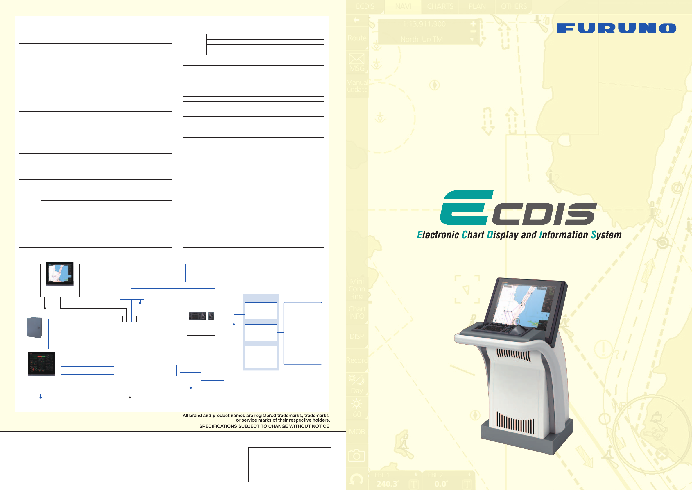
SPECIFICATIONS
Product Name
Standards
Monitor Unit
Chart Materials
Display
Modes
Data
Presentation
Alarm Information
Position Calculation
Navigation Planning
Navigation Recording
Route Monitoring
User Chart
MOB (Man Overboard)
Interface
FMD-3200
FMD-3300
True Motion
Relative Motion
Own Ship
Target Tracking
(TT: ARPA, AIS)
Cursor
DVI
LAN
USB
COM
Serial I/O
Digital IN
Contact Closure
ELECTRONIC CHART DISPLAY AND INFORMATION SYSTEM
IMO MSC.232(82), IMO A.694(17), IMO MSC.191(79), IEC 61174 Ed. 3,
IEC 61162-1 Ed. 4, IEC 61162-2 Ed. 1, IEC 62288, IEC 60945 Ed. 4
MU-190, 19" color LCD, SXGA (1284 x 1024 pixels)
MU-231, 23.1" color LCD, UXGA (1600 x 1200 pixels)
IMO/IHO S57 edition-3 ENC vectorized material
(IHO S-63 ENC data protection scheme),
ARCS rasterized material,
C-MAP and CM-93/3 vectorized materials
North-up, Course-up, Route-up
North-up, Course-up, Route-up, Heading-up
Own ship's mark/trip and numeral position in lat/lon, speed
and course
Range, bearing, speed, course, CPA/TCPA
Target information from AIS (waypoint, ship's hull and status)
EBL, VRM
Waypoint, route monitoring and several alarms
Navigation by result from external position sensor
Dead reckoning with gyro and log
Data from gyro, log, and position sensors to be fed to
mathmatical filter to generate highly accurate position and speed
Planning by rhumb line, great circle
Latest 12 hours of navigation data to be recorded
Off-track display, waypoint arrival alarm, shallow depth alarm
User chart creation and display (up to 100 user chart can be
created; 4000 points can be included per 1 user chart),
notes function available
Position, and other data at time of man overboard are recorded
MOB mark is displayed on the screen
3 ports, DVI-I Ver 1.1 (Video signal from DVI No. 1 and
DVI No. 2 is identical, and DVI No. 3 is for conning display)
3 ports, Ethernet 1000 Base-T (1 port is for radar sensor only)
4 ports, USB 2.0 type-A
2 ports, RS-485 for brilliance control
8 ports, IEC61162-1/2 (2 ports), IEC61162-1 (6 ports)
Sentences: ABK, ABM, ACA, ACK, AIR, BWC, BWR, DBK,
DBS, DBT, DPT, DSC, DSE, DTM, FSI, GGA, GLL, GNS,
HDG, HDM, HDT, RMA, RMB, RMC, RTE, ROT, THS, MTW,
MWV, VDR, VDM, VDO, VHW, VTG, VWR, WPL, ZDA, ALR
1 port, ACK signal input
6 ports: 1 port for system fail, 1 port for power fail,
2 ports open and 2 ports close
INTERCONNECTION DIAGRAM
SENSOR ADAPTER
1 port, Ethernet 100 Base-TX
LAN
8 ports, IEC 61162-1/2 (4 ports), IEC 61162-1 (4 ports)
Control and
Serial Input
Analog Input
Digital Input
Digital output
Serial
Contact
1 port for system fail, normal close or normal open
Closure
3 ports/unit, -10 to +10V or 0 to 10V, 4 to 20 mA, selectable
8 ports/unit, normal close or open, selectable
8 ports/unit, normal close or open, selectable
POWER SUPPLY
Processor Unit
Sensor Adapter
Monitor Unit
100-115/220-230 VAC, 1 phase, 50/60 Hz
24 VDC, 1.4 A
100-230 VAC, 1 phase, 50/60 Hz
ENVIRONMENTAL CONDITION
Ambient Temperature
Relative Humidity
Degree of Protection
Vibration
-15˚C to +55˚C
93 % or less at 40˚C
IP20 (IP22: option)
IEC 60945 Ed. 4
EQUIPMENT LIST
Standard
1 Monitor Unit MU-190 for FMD-3200, MU-231 for FMD-3300 1 unit
2 Processor Unit EC-3000 1 unit
3 ECDIS Control Unit RCU-024 or Trackball Control Unit RCU-026
(specify when ordering) 1 unit
4 Standard Spare Parts and Installation Materials 1 set
Option
1 Sensor Adapter: 1 set
MC-3000S Control Serial
MC-3010A Analog
MC-3020D Digital IN
MC-3030D Digital OUT
2 Trackball Control Unit RCU-026 (for remote control) 1 unit
3 Switching Hub HUB-100 for sensor network 1 unit
4 Intelligent Hub HUB-3000 for interswitch network 1 unit
5 AC/DC Power Supply Unit PR-240 1 unit
6 Installation Materials 1 set
Models: FMD-3200
(
with 19" LCD
)
/ FMD-3300
(
with 23.1" LCD
)
Monitor Unit
MU-190/231
100-230 VAC
VDR
RS-485 5/10 m for brilliance control
RGB 30 m max.
VR-3000
Monitor Unit
MU-190/231
for Conning Display
100-230 VAC
FURUNO ELECTRIC CO., LTD.
Nishinomiya, Hyogo, Japan
www.furuno.com
FURUNO U.S.A., INC.
Camas, Washington, U.S.A.
www.furunousa.com
FURUNO (UK) LIMITED
Havant, Hampshire, U.K.
www.furuno.co.uk
FURUNO FRANCE S.A.S.
Bordeaux-Mérignac, France
www.furuno.fr
MU-190: DVI 5/10 m (max.)
MU-231: DVI 5 m (max.)
DVI-analog
RGB
conversion kit
MU-190: DVI 5/10 m (max.)
MU-231: DVI 5 m (max.)
RS-485 5/10 m
for brilliance control
FURUNO ESPAÑA S.A.
Madrid, Spain
www.furuno.es
FURUNO DANMARK A/S
Hvidovre, Denmark
www.furuno.dk
FURUNO NORGE A/S
Ålesund, Norway
www.furuno.no
FURUNO SVERIGE AB
Västra Frölunda, Sweden
www.furuno.se
HUB-3000
100-230 VAC
or Serial/USB 2.3/5 m
Processor
EC-3000
or Serial/USB 2.3/5 m
100-115/220-230 VAC
FURUNO FINLAND OY
Espoo, Finland
www.furuno.
FURUNO POLSKA Sp. Z o.o.
Gdynia, Poland
www.furuno.pl
FURUNO EURUS LLC
St. Petersburg, Russian Federation
www.furuno.com.ru
Serial 10/20/30 m
Serial 10/20/30 m
Processor EC-3000 for ECDIS
and Chart Radar*
ECDIS
Control Unit
RCU-024
RCU-026
Trackball
Control Unit
HUB-100
100-230 VAC
or
24 VDC
Note:
1. Length of LAN cable is 50 m (max.)
2. Cable between Sensor Adapter components
Option or connectable equipment
FURUNO DEUTSCHLAND GmbH
Rellingen, Germany
www.furuno.de
FURUNO HELLAS S.A.
Piraeus, Greece
www.furuno.gr
RICO (PTE) LTD
Singapore
www.rico.com.sg
should be no longer than 6 m.
Sensor Adapter
Serial
MC-3000S
(8 ports)
Analog
MC-3010A
(3 ports)
Digital IN/OUT
MC-3020D/
3030D
(8 ports each)
* Up to 8 EC-3000 Processors can be
interfaced through single HUB-3000.
Navigation Sensors
Gyrocompass
AIS
GPS
NAVTEX
Wind Indicator
Echo Sounder
Speed Log
Water Temp. Sensor
etc.
12022SK Printed in Japan
Catalogue No. M-1558
with an optional pedestal
www.furuno.com
Page 2
Fast, intuitive route planning and navigation monitoringFast, intuitive route planning and navigation monitoring
▲
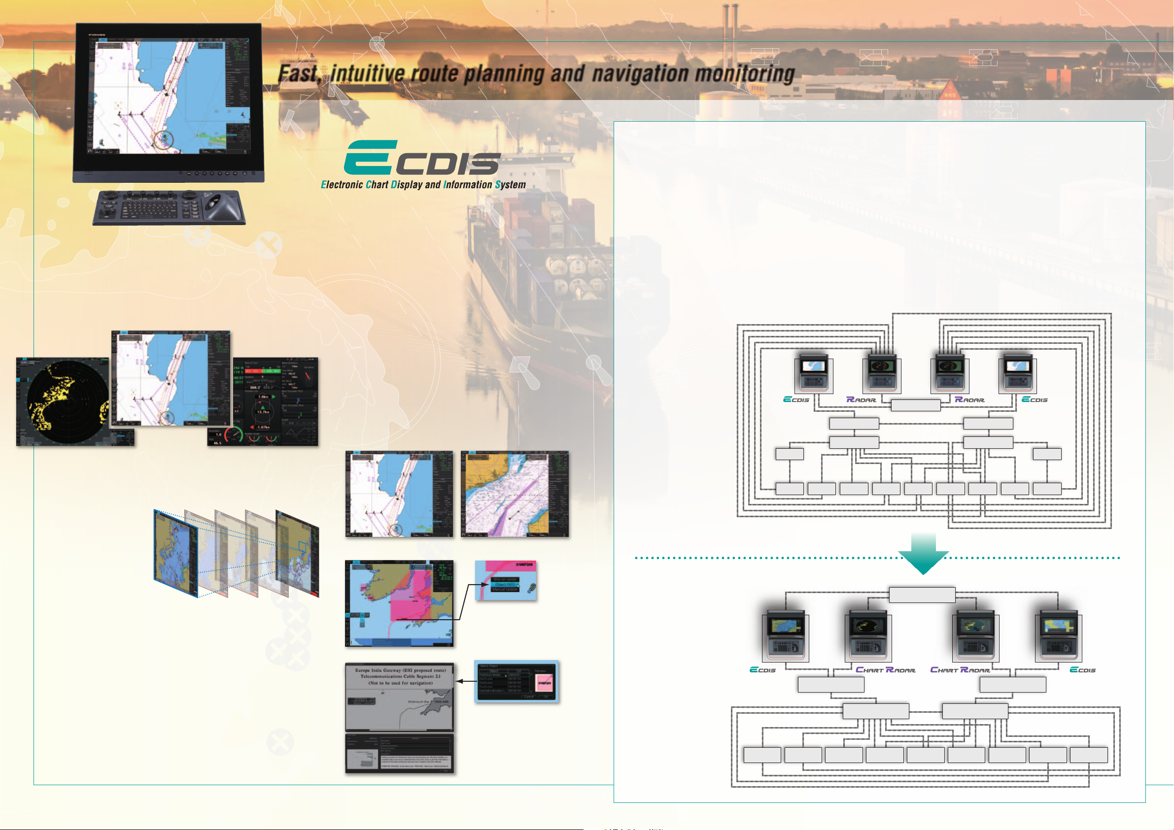
Ease of installation and maintenance thanks to simplied cabling in the sensor-to-ECDIS/Radar interface
delivered by common sensor adapter
Sensor Adapter acts as central medium to gather all the sensor data and collectively feed it to all FMD-3200/3300 ECDIS and FCR-2xx9 Chart Radar in the system.
Since sensor adapter can be extended to cover all the sensors within the system, individual cablings in the sensor-to-ECDIS/Radar interface can be greatly reduced.
▲
Multifunction display capability, featuring ECDIS,
Conning Information Display, Radar/Chart Radar* and
Alert Management System**
* a radar sensor needs to be integrated in the network.
** Radar and Alert Management System display capabilities are to be implemented as
software update after product release. (option)
ECDIS
Radar Conning Information Display
▲
Instantaneous chart redraw delivered by FURUNO’s
advanced chart drawing engine, making redraw latency
a thing of the past
Models: FMD-3200 (with 19" LCD) / FMD-3300 (with 23.1" LCD
▲
Compatible cartography
• IHO/S-57 Edition 3 vector chart
Admiralty Vector Chart Service by UKHO ・C-MAP ENC
・
Jeppesen Primar ECDIS Service
・
• ARCS raster chart
• C-MAP Professional+*
*C-MAP Professional+ is a private chart, hence not construed as replacement for paper chart.
▲
Interface with Jeppesen Dynamic Licensing Service
available
▲
Compatibility with Admiralty Information Overlay
(AIO) for further navigation safety
Additional AIO layer includes all Admiralty Temporary and Preliminary
Notices to Mariners as well as additional ENC Preliminary Notices to
Mariners, i.e., reported navigational hazards that have been incorporated
into paper chart but have yet to be included in ENCs. The service is free
of charge as part of Admiralty Vector Chart Service (AVCS) by UKHO.
(IHO S-63 data protection scheme)
)
Navigation sensors can be directly interfaced with the ECDIS processor’s 8 serial I/O ports.
Sensor adapters are required under the following conditions:
• the sensor data is to be shared amongst multiple networked ECDIS and Radar systems,
• the number of sensors interfaced is more than the number of the ports the processor has (8 serial I/O ports, 1 digital IN and 6 digital OUT), and/or
• the networked sensors include analog sensors.
In order to integrate onboard sensors into the navigation network, the sensor adapter may be interfaced with the switching hub
HUB-100 from which distribution of the sensor data throughout the network is possible.
Alternatively, multiple sensor adapters may be interfaced via Ethernet to integrate onboard sensors for use in the shipboard network.
System diagram
for the current
Model
Model:
FEA-2X07
HUB100
HUB100
LAN Adapter
B Adapter
Gyro 1 Gyro 2GPS 1 GPS 2HCS Speed log
Anemometer
Nav. E.S. AIS
HUB100
LAN Adapter
B Adapter
Instantaneous chart redraw
▲
Intuitive new user interface offers fast, precise route
planning, monitoring and navigation data management
▲
Interface with existing FAR-21x7/FAR28x7 series
Radar for Radar overlay, target track info, route
and waypoint exchange via Ethernet
▲
Complies with the following IMO and IEC
regulations:
• IMO MSC.232(82)
• IMO A.694(17)
• IEC 61174 Ed. 3
• IEC 61162-1 Ed. 4
• IEC 61162-2 Ed. 1
• IEC 62288
Electronic Navigational Chart Raster Navigational Chart
Place the cursor on the AIO object
and right-click to open the contextual
menu. Select “Object INFO” to open
the chart object window.
AIO data layer displayed
Chart object window
On the chart object window,
select the AIO object and click
"OK" to view the details.
The full text of the Notice to Mariners
as well as associated diagrams can
be displayed subsequently.
System diagram
for the new Model
Models:
FMD-3200/3300
HUB100 HUB100
Gyro 1 Gyro 2GPS 1 GPS 2HCS Speed log
HUB3000
Anemometer
Sensor AdapterSensor Adapter
Nav. E.S. AIS
Page 3
FURUNO’s new user interface delivers straightforward,
task-based operation
FURUNO’s new user interface delivers straightforward,
Items on the upper part of the InstantAccess bar:
Monitor Mode
In the Monitor Mode, ship’s behaviour can be monitored in
relations to the planned route. Various voyage monitoring
tools are incorporated into the InstantAccess bar.
Chart Maintenance Mode
The Chart Maintenance Mode allows the operators to
handle charts to be used in the system
1
2
3
4
5
6
7
8
chart license menu window
Click to start automatic installation of the chart data from
the chart CD or DVD ROM.
Click to manage charts, i.e., grouping chart cells by
purposes, deleting unnecessary chart cells, etc.
Click to view the chart catalog that shows general
information about the charts installed in the system, i.e.,
coverage, license status, availability and other status
information.
Click to open the chart license menu window where the
operators can view the permit status of the chart installed.
Also, the operators can install, backup, restore and export
the chart licenses from the same menu window.
Click to open Public Key management window.
This allows user to change the Public Keys which are
used to authenticate the source and integrity of the chart
materials used in ECDIS.
4
5
6
7
8
Select:
Click to open route selecting menu window to select
the route to monitor.
Unselect:
Click to stop monitoring the route.
Move to plan:
Click to transfer the route currently being
monitored to the Plan Mode in order to amend the route.
Route INFO:
Click to open the route information window
where the detailed parameters set for each waypoint within the
route as well as the details of the user chart can be veried.
Also, notes/cautions on status of the monitored route as well
as user chart can be viewed.
Click to open the
AIS/NAVTEX message
menu window from which
the operators can handle
AIS/NAVTEX messages,
i.e., sending, viewing and
deleting the messages.
Click to open the manual update menu window by which the
operators can update the electronic chart by inserting chart
update symbols manually, according to the Notices to
Mariners, NAVTEX warnings, etc. Manual update of the chart is
required to ensure that the chart is kept up to date at all times.
When the ofcial chart update containing the changes by the
manual update is made, the operator can delete the manual
update symbols through the manual update menu window.
AIS/NAVTEX message dialog box
1
2
3
Route monitoring
Radar overlay
IMO ECDIS Model Course 1.27
(Generic ECDIS training)
FURUNO’s provision of thoroughgoing ECDIS training programs
Proper training is required to ensure an efcient and safe operation of vessels as well as to
optimize the advantages of having ECDIS onboard. Advantages include less time spent on chart
management and voyage planning and increased safety through the proper setup and operation of
the ECDIS, which can remarkably reduce the risk of groundings, etc. Training comes in many
forms and the crew should undergo both generic training to get full understanding of the ECDIS as
a concept, the rules governing ECDIS and the inuences on the bridge operation. Crews should
also receive type specic ECDIS training, which helps the operator familiarize themselves with the
specic ECDIS onboard the vessel. FURUNO offers the ECDIS trainings through its INS Training
Centers (INSTC in Copenhagen and Singapore) as well as other training facilities signed up as
NavSkills™ training facilities. NavSkills™ training solution is the service and support for maritime
training centers and shipowners, who are looking to establish their own training facilities in full
compliance with STCW and IMO standards. NavSkills™ training package includes provision of
training simulators, provision and update on course materials and curriculum, training for
instructors, certication of the trainees by INSTC and much more.
STCW requires that all masters and ofcers in charge of a navigational watch (Ofcer of the
Watch: OOW) on a ship tted with ECDIS shall have completed a generic ECDIS course and
hold an ECDIS certicate in accordance with IMO model course 1.27.
This ECDIS training provides the trainees with knowledge of the ECDIS as a system,
its operation, electronic chart materials and practical navigation. Also, the course includes
terms and conditions for implementing paperless navigation. The training course focuses upon
many advantages and safety features obtained by operating ECDIS. The limitations of ECDIS
are taught throughout this training course.
This training concludes with 3 compulsory tests, and, if passed, a certicate is issued, which
conrms the trainees' successful completion of the generic ECDIS training in accordance with
IMO Model Course 1.27, reviewed by DNV SeaSkill™.
The course is available at INSTC Denmark.
Type specic ECDIS training course
FURUNO type specic ECDIS training provides trainees with specic knowledge about
functionality and effective use of FURUNO ECDIS for navigation.
The training covers the following aspects of FURUNO ECDIS operation:
• Familiarisation with available functions • familiarisation with the menu structure
• Display setup • Setting safety value • Route planning • Route monitoring
• Recognition of alarm and malfunction indicators and the actions to be taken
• Changing over to backup systems • Loading and updating of charts and licenses
• Updating software
The training concludes with a compulsory test. Upon successful completion of the test, the
navigators are issued a certicate that conrms the successful completion of the FURUNO
type specic ECDIS training course. This training complies with the STCW and ISM Codes,
audited and certied by ClassNK (only for INSTC Denmark and INSTC Singapore).
The course is available at INSTC Denmark, INSTC Singapore, FURUNO Deutschland GmbH,
OCEAN TRAINING CENTER (Turkey) and GMC Maritime Training Center (Greece).
task-based operation
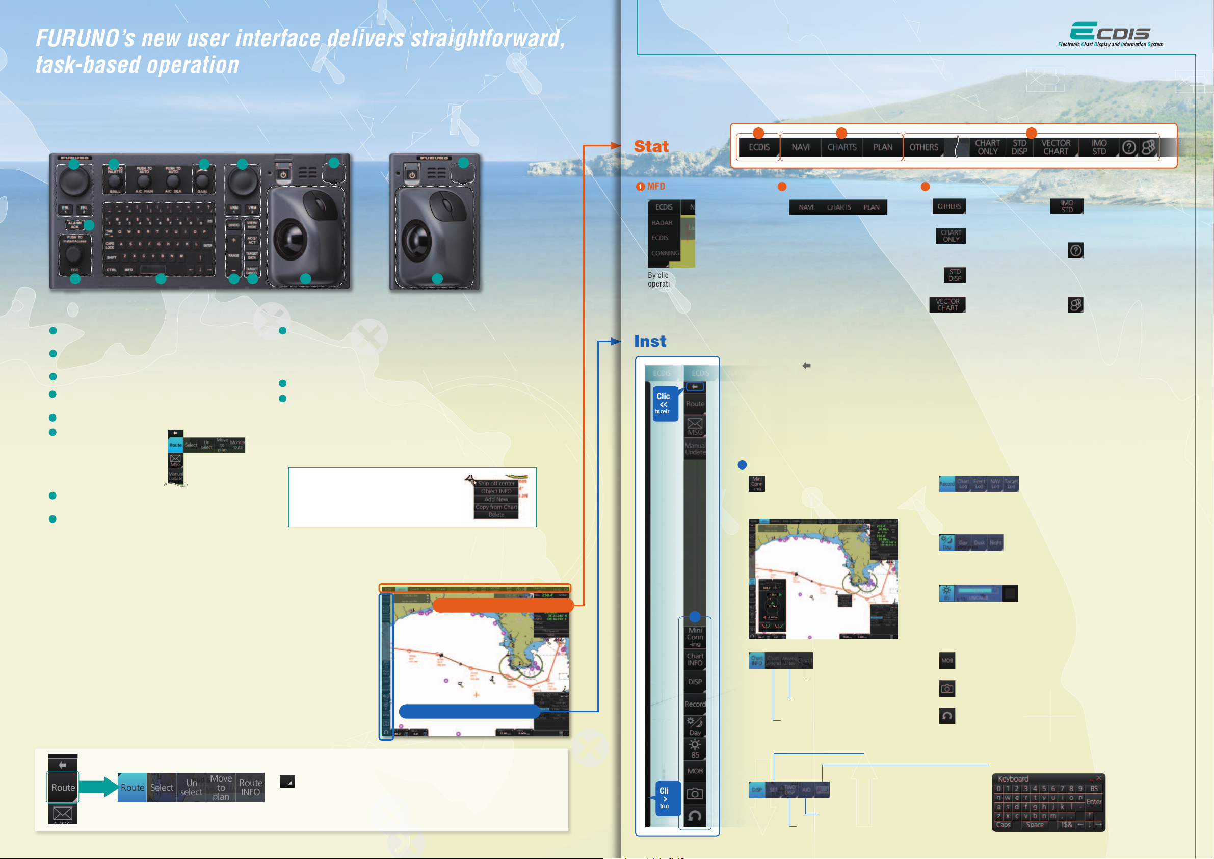
ECDIS Control Units
The operator control of the FMD-3200 and FMD-3300 can be done with the ECDIS Control Unit RCU-024 or the Trackball Control Unit RCU-026.
All functions of the ECDIS can be accessed by using the trackball, scrollwheel and left/right clicking.
1 2 3 4
10
5
6
ECDIS Control Unit RCU-024 Trackball Control Unit RCU-026
1
Press “EBL 1” and “EBL 2” to activate/deactivate respective EBL;
and rotate the encoder to adjust active EBL.
2
Rotate to adjust brilliance level of the FURUNO monitor; and
press to select display palette.
3
Rotate to adjust radar gain on the radar overlay.
4
Press “VRM 1” and “VRM 2” to activate/deactivate respective
VRM; and rotate the rotary encoder to adjust active VRM.
5
For acknowledgement of alerts generated.
6
Rotate to select items within the
I.A.bar; and press to confirm the
selection of the item.
7
Full QWERTY keyboard for easy entery of route, event and
waypoint names.
Following functions are assigned for each key:
UNDO: to undo the last operation
RANGE: to select chart scale
7
InstantAccess bar
889
11 11
9
Following functions are assigned for each key:
VIEW/HIDE: to show/hide the I.A. bar and route information window
ACQ/ACT: to activate selected active AIS target
TARGET DATA: to display the detailed target data for selected TT/AIS
TARGET CANCEL: to sleep the selected active AIS target
10
USB port for charts update, import/export, WP/routes, user setting.
11
Trackball Module
Trackball module consists of four parts, each of which has the following functions:
trackball: to move the cursor and select an object
left-click: to perform/confirm the action related the selected object
right-click: to display context menu while a cursor is on the display area, and to
cancel action done on the selected object
scrollwheel: to select menu items
Contextual Menu
Right-clicking on the screen will open the contextual menu
containing all the available actions related to the position of
the cursor, i.e., chart object, data box, etc., hence providing
quick access to tasks required.
Task-based user interface realized by combination of Status bar and
InstantAccess bar providing quick access to
the needed tasks/functions
The user interface of the FMD-3200/FMD-3300 centers on carefully
organized operational tools: Status bar and InstantAccess bar.
The Status bar at the top of the screen contains information about the
operating status, i.e., MFD operating mode, the ECDIS operation
modes, etc. InstantAccess bar at the left-hand side of the screen
contains all the tasks (functions/actions) corresponding to the ECDIS
operation mode currently selected. These operational tools deliver
straightforward, task-based operation by which the operator can quickly
perform navigational task without having to go deeper into an intricate
menu tree.
Drop-down menu to facilitate streamlined operation
Click to open
on buttons in the Status bar and InstantAccess bar indicate that
there are hidden options of actions/tasks to be performed in the
sub-layer, which can be initiated by left-clicking the buttons.
This way, the operator can quickly gain access to the related tasks.
InstantAccess bar
10
Status bar
Status bar
1
MFD operating mode selector
By clicking this button, the MFD
operating mode selector will open.
InstantAccess bar
Click
<<<
to retract
Click
>>>
to open
When clicking on the InstantAccess bar, the InstantAccess bar will retract to the edge of the screen.
By clicking the hidden bar at the edge of the screen, the InstantAccess bar will come back in.
The upper part of the InstantAccess bar contains the list of available tasks/functions specic to each of the ECDIS
operation modes selected, hence providing quick access to the needed tasks/functions to be performed. While the
menu items of the upper part of the InstantAccess bar change according to the mode selected, the lower part of the
InstantAccess bar is static for all modes, except for “Mini Conning”, which is only available in the “Monitor mode”
and “Plan mode”.
1
Items on the lower part of the InstantAccess bar:
1
Click to show and hide the mini conning display, only
available in the “Monitor mode” and “Plan mode”.
2
Operation Mode
These three buttons give quick access
to the three ECDIS operation modes:
“Monitor mode”, “Chart Maintenance
mode” and “Plan mode”. Once an
operation mode is selected, the upper
part of the InstantAccess bar will
change accordingly, providing quick
access to the tasks specific to each of
the ECDIS operation modes.
Click to view over view of ECDIS
chart symbols.
Click to open a char t viewing date
setup window.
Click to view various data about the chart
currently displayed, the contents of which
depend upon the t ype of chart displayed.
Click to enter setting windows for chart/symbol display as well as chart alert.
Click to display Admiralty Information Overlay.
Click to split the screen in t wo (two-way split screen).
31 2
3
Other buttons on the Status bar
Click to record user/position events to the event log as well as to access
various logs to observe, including: navigation logs (details log, voyage log
and chart usage log), target log and alert log.
Click to select a color palette (color and brilliance set of the screen
presentation) to match the ambient lighting conditions.
Click to summon display brilliance level adjustment window where the
brilliance level can be adjusted either manually (by gauge) or
automatically (by clicking the automatic brilliance adjustment button, next
to the brilliance gauge).
Click to play back log.
Shows only the chart,
while long-pressed by the
left-click key.
Click to restore the IMO
standard display.
Click to set priority order of
chart to be displayed.
Click to enter Man Overboard mark on the char t.
Click to take a screenshot.
Click to undo/redo the past actions.
Click to activate on-screen keyboard.
Click to select IMO chart
display setting: IMO BASE,
IMO STD or IMO-ALL.
Click to display the
operator’s manual, ECDIS
program number and
system information.
Click to select, manage and
set the user profile.
Page 4
Items on the upper part of the InstantAccess bar:
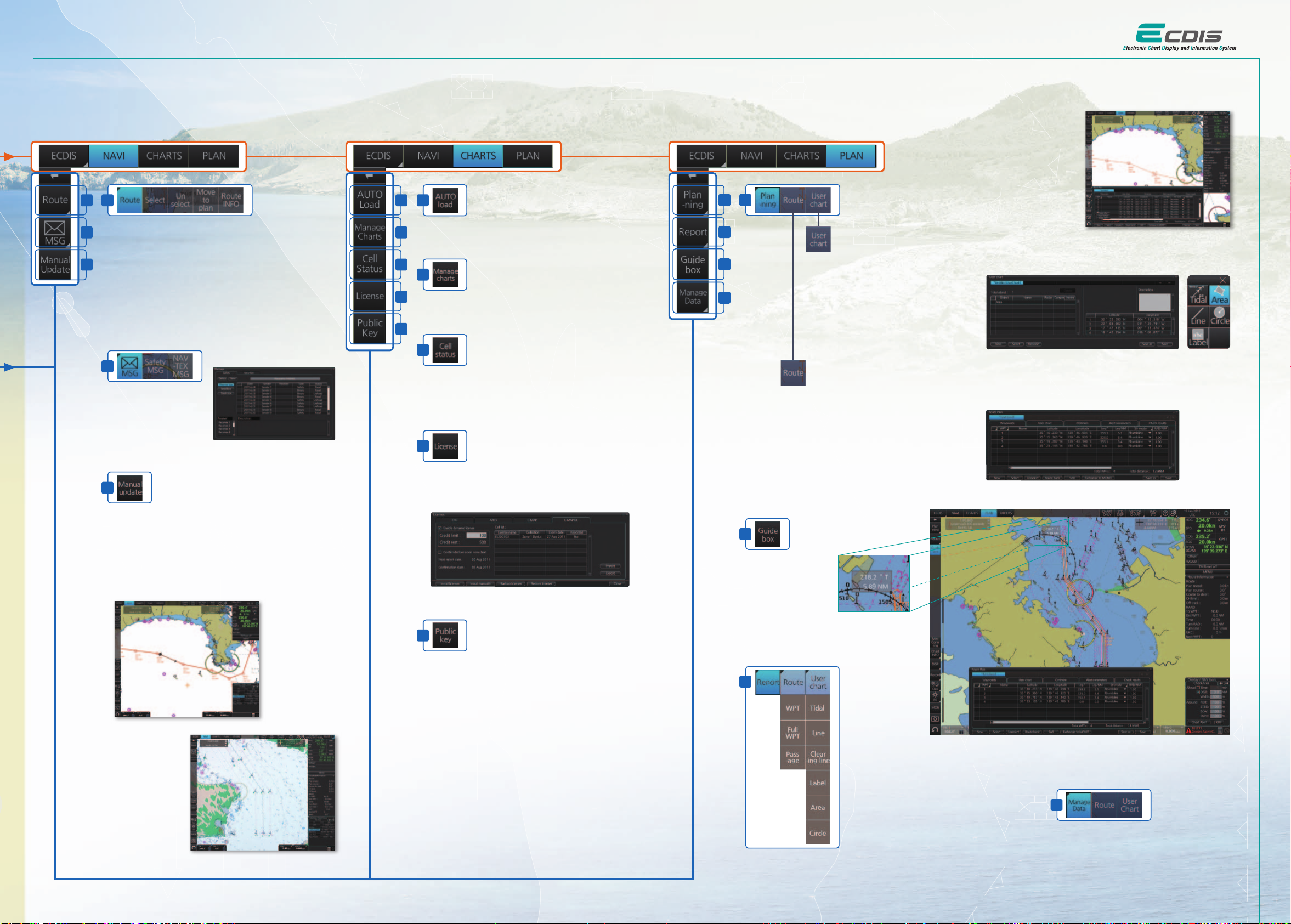
Monitor Mode
In the Monitor Mode, ship’s behaviour can be monitored in
relations to the planned route. Various voyage monitoring
tools are incorporated into the InstantAccess bar.
1
1
Click to open route selecting menu window to select
Select:
2
the route to monitor.
Unselect:
Move to plan:
3
monitored to the Plan Mode in order to amend the route.
Route INFO:
where the detailed parameters set for each waypoint within the
route as well as the details of the user chart can be veried.
Also, notes/cautions on status of the monitored route as well
as user chart can be viewed.
2
Click to open the
AIS/NAVTEX message
menu window from which
the operators can handle
AIS/NAVTEX messages,
i.e., sending, viewing and
deleting the messages.
3
Click to open the manual update menu window by which the
operators can update the electronic chart by inserting chart
update symbols manually, according to the Notices to
Mariners, NAVTEX warnings, etc. Manual update of the chart is
required to ensure that the chart is kept up to date at all times.
When the ofcial chart update containing the changes by the
manual update is made, the operator can delete the manual
update symbols through the manual update menu window.
Click to stop monitoring the route.
Click to transfer the route currently being
Click to open the route information window
AIS/NAVTEX message dialog box
Chart Maintenance Mode
The Chart Maintenance Mode allows the operators to
handle charts to be used in the system
4
4
Click to start automatic installation of the chart data from
5
the chart CD or DVD ROM.
6
5
7
Click to manage charts, i.e., grouping chart cells by
purposes, deleting unnecessary chart cells, etc.
8
6
Click to view the chart catalog that shows general
information about the charts installed in the system, i.e.,
coverage, license status, availability and other status
information.
7
Click to open the chart license menu window where the
operators can view the permit status of the chart installed.
Also, the operators can install, backup, restore and export
the chart licenses from the same menu window.
chart license menu window
Plan Mode
In the Plan mode, the operators can generate and edit route plans as well as user charts. Also, various detailed
reports, generated by ECDIS, on planned routes as well as user charts can be
viewed. All these tasks can be accessed from the InstantAccess bar.
9
9
10
11
12
11
A guide box instantly
tells the operators the
range and bearing
between the last
waypoint and the
cursor position as you
drag the cursor.
Creating User Chart:
When clicking on “User chart”, user chart tools
(a palette and a menu window) will be displayed
by which operators can create a user chart.
A user chart is a layer consisting of marks and
lines that can be produced and overlaid onto the
chart. It is intended for indicating safety-related
areas and objects.
User Chart Tools
Route Planning:
Once left-clicking on “Route”, a route planning menu
window will open. The operators can use the trackball
to enter waypoints directly onto the chart. After entering
a waypoint, the operators can edit name, steering
mode, radius, channel limit and other parameters of the
waypoints on the menu window.
Route Planning Dialog Box
Route planning
Route monitoring
Radar overlay
8
Click to open Public Key management window.
This allows user to change the Public Keys which are
used to authenticate the source and integrity of the chart
materials used in ECDIS.
10
Route Planning Display
Quick access to various reports:
Route reports on waypoints and passage plan
as well as user chart reports on tidals, lines,
user-entered objects and user-dened areas
can be directly accessed for viewing from the
InstantAccess bar.
12
Click to open the data management windows for
routes as well as user charts where selected
routes and user charts can be deleted.
Page 5

FURUNO’s provision of thoroughgoing ECDIS training programs
▲
Contact Info
Proper training is required to ensure an efcient and safe operation of vessels as well as to
optimize the advantages of having ECDIS onboard. Advantages include less time spent on chart
management and voyage planning and increased safety through the proper setup and operation of
the ECDIS, which can remarkably reduce the risk of groundings, etc. Training comes in many
forms and the crew should undergo both generic training to get full understanding of the ECDIS as
a concept, the rules governing ECDIS and the inuences on the bridge operation. Crews should
also receive type specic ECDIS training, which helps the operator familiarize themselves with the
specic ECDIS onboard the vessel. FURUNO offers the ECDIS trainings through its INS Training
Centers (INSTC in Copenhagen and Singapore) as well as other training facilities signed up as
NavSkills™ training facilities. NavSkills™ training solution is the service and support for maritime
training centers and shipowners, who are looking to establish their own training facilities in full
compliance with STCW and IMO standards. NavSkills™ training package includes provision of
training simulators, provision and update on course materials and curriculum, training for
instructors, certication of the trainees by INSTC and much more.
IMO ECDIS Model Course 1.27
(Generic ECDIS training)
STCW requires that all masters and ofcers in charge of a navigational watch (Ofcer of the
Watch: OOW) on a ship tted with ECDIS shall have completed a generic ECDIS course and
hold an ECDIS certicate in accordance with IMO model course 1.27.
This ECDIS training provides the trainees with knowledge of the ECDIS as a system,
its operation, electronic chart materials and practical navigation. Also, the course includes
terms and conditions for implementing paperless navigation. The training course focuses upon
many advantages and safety features obtained by operating ECDIS. The limitations of ECDIS
are taught throughout this training course.
This training concludes with 3 compulsory tests, and, if passed, a certicate is issued, which
conrms the trainees' successful completion of the generic ECDIS training in accordance with
IMO Model Course 1.27, reviewed by DNV SeaSkill™.
The course is available at INSTC Denmark.
FURUNO INS Training Center Singapore
No. 17, Loyang Lane, Singapore 508917
Phone: +65 6745 8472
E-mail: [email protected]
FURUNO INSTC
NavSkills™ facilities
FURUNO INS Training Center Denmark
Hammerholmen 44-48, DK-2650 Hvidovre, Denmark
Phone: +45 36 77 40 12
E-mail: [email protected]
FURUNO Deutschland GmbH
Siemensstrasse 33
D-25462 Rellingen
Germany
Phone: +49 4101 838 203
E-mail: [email protected]
OCEAN TRAINING CENTER
(
Part of ÖZSAY MARINE GROUP
Guzelyali Mah., Ankara Asfalti E-5, Üzeri No. 18
TR-34903 Pendik, Istanbul
Turkey
Phone: +90 216 493 3610
E-mail: [email protected]
Monitor Unit
MU-190 8.8 kg 19.4 lb MU-231 12.8 kg 28.2 lb
397 15.6"
450 17.7"
489 19.3"
110 4.3"
448 17.6"
4-Ø18
389 15.3"
Cutout for ush mount
484.9 19"
553 21.8"
592 23.3"
Control Unit
RCU-024
3.3 kg 7.3 lb
339 13.35"32 1.26"
180 7.09"
398 15.67"
Processor Unit
EC-3000
14 kg 30.9 lb
426 16.77"
15 0.59"
396 15.59"
360 14.17"
45 1.77"150 5.9" 150 5.9"
216 8.5"
18 0.71"
153 6.02"
150 5.9"
55
2.17"
38
1.5"
no less than
72 2.83"
10 to 20
0.39" to 0.79"
Switching Hub
HUB-100
1.5 kg 3.31 lb
170 6.69"
270 10.63"
255 10.03"
398 15.67"
388 15.28"
4-ø5
Fixing Hole
180 7.09"
47 1.85"
45
1.77"
)
47 Gounari Street
GR- 185 31 Piraeus
Greece
Phone: +30 210 4124040
E-mail: [email protected]
112
4.4"
471 18.5"
Trackball Control Unit
GMC Maritime Training Center
RCU-026
1.5 kg 3.3 lb
180 7.09"
no less than 70 2.76"
120 4.72"
Intelligent Hub
HUB-3000
1.5 kg 3.31 lb
350 13.79"
336 12.23"
554 21.8"
Cutout for ush mount
170 6.69"
4-ø5
Fixing hole
120 4.72"
110 4.33"
Max 70
2.76"
180 7.09"
42 1.65"
Type specic ECDIS training course
FURUNO type specic ECDIS training provides trainees with specic knowledge about
functionality and effective use of FURUNO ECDIS for navigation.
The training covers the following aspects of FURUNO ECDIS operation:
• Familiarisation with available functions • familiarisation with the menu structure
• Display setup • Setting safety value • Route planning • Route monitoring
• Recognition of alarm and malfunction indicators and the actions to be taken
• Changing over to backup systems • Loading and updating of charts and licenses
• Updating software
The training concludes with a compulsory test. Upon successful completion of the test, the
navigators are issued a certicate that conrms the successful completion of the FURUNO
type specic ECDIS training course. This training complies with the STCW and ISM Codes,
audited and certied by ClassNK (only for INSTC Denmark and INSTC Singapore).
The course is available at INSTC Denmark, INSTC Singapore, FURUNO Deutschland GmbH,
OCEAN TRAINING CENTER (Turkey) and GMC Maritime Training Center (Greece).
Sensor Adapter
Serial
MC-3000S
1.5 kg 3.3 lb
150 5.91"64 2.52"
235.5 9.27"
220 8.66"
180 7.09"
3-ø8
Fixing hole
4-ø5
Fixing
Hole
48 1.88"
41 1.61"
Analog
MC-3010A
0.8 kg 1.8 lb
100 3.94"
60 2.36"
4-ø5
Fixing
Hole
242 9.53"
150 5.91" 64 2.51"
48 1.88"
41 1.61"
235.5 9.25"
162 6.38"
115 4.53"
15 0.59"
Digital In
MC-3020D
0.8 kg 1.76 lb
4-ø5
Fixing
Hole
145 5.71"
100 3.94"
60 2.36"
324 12.76"
48 1.88"
41 1.61"
150 5.91"64 2.52"
235.5 9.25"
no less than 150 5.91"
Digital Out
MC-3030D
0.8 kg 1.76 lb
100 3.94"
60 2.36"
4-ø5
Fixing
Hole
153 6.02"
133 4.06"
33
1.3"
150 5.91"64 2.52"
172 6.77"
no less than 150 5.91" no less than 100 3.94"
48 1.88"
41 1.61"
235.5 9.25"
no less than 150 5.91"
 Loading...